Note: Descriptions are shown in the official language in which they were submitted.
CA 02360738 2001-10-31
DUMP TRUCK APPARATUS WITH REMOVABLE HOPPER
FIELD OF THE INVENTION
The present invention relates to the field of dump trucks, and more
particularly to
dump trucks capable of being used as spreader trucks.
BACKGROUND OF THE INVENTION
Large scale civil projects such as road construction, road repairs, or snow
removal
normally require the use of certain types of heavy equipment, and in
particular, certain
types of vehicles, for their successful completion. Different types of
vehicles may be used
for different purposes.
For example, one type of vehicle commonly utilized during municipal or
construction projects is the dump truck. As known by those skilled in the art,
dump trucks
have a dump body that is capable of being pivoted upwardly about a rear axis
transverse
to the length of the truck for rapid unloading of materials contained therein.
Dump trucks
are useful for hauling heavy loads comprising various types of materials, such
as earth or
crushed stone, and easily depositing them in a desired location.
Another type of vehicle that can be very useful is the spreader truck.
Spreader
trucks are vehicles that are capable of hauling dispersible materials, such as
sand or salt,
and spreading these materials over the underlying ground surface (usually when
the
vehicle is in motion). Spreader trucks typically have a body consisting of a
generally V-
shaped hopper with a conveyor at the bottom for feeding material back towards
the rear of
the truck. The "V" shape of the body promotes effective gravity feeding of
contained
materials into the conveyor. In typical operation, the conveyor is engaged to
convey the
materials rearwardly onto one or more "spreaders" (e.g. spinning plates with
radiai
upstanding ribs) for dispersion over an expanse of undertying road. Spreader
trucks of this
-1-
CA 02360738 2001-10-31
type are commonly used in colder climates to disperse granular salt onto ice-
covered
roadways.
Unfortunately, vehicles such as dump trucks and spreader trucks can be
expensive. As a result, it can be difficult for some entities, such as
municipalities or
enterprises with limited budgets, to be able to afford all of the various
types of vehicles
that they may require.
Recognizing this problem, at least one manufacturer has thought to produce a
vehicle that is capable of being used in multiple capacities. The rationale of
this approach
is that, because the bulk of the expense of a heavy vehicle may be
attributable to its
understructure (i.e. chassis, wheels, engine, drive train, cab, etc.) as
opposed to its
accessories (e.g. hopper, spreader, or dumping actuator), it is more
economical to provide
a single vehicle understructure that can be configured for use in various
capacities.
A known apparatus following this approach is the combined dump truck and
spreader apparatus described in US Patent 5,772,389. The dump truck of this
patent has
a dump body with a generally semi-circular cross-section and an integral
conveyor
attached at its base that is capable of conveying materials back towards the
rear of the
truck. A latchable tailgate is pivotally secured to the rear of the body. A
hoist mechanism
at the front of the dump body is capable of inclining the body with the
attached conveyor
for rapid unloading of materials, in the manner of a conventional dump truck.
When used
as a dump truck, a cover is placed over the conveyor mechanism at the base of
the dump
body to prevent any material from flowing thereinto, and the conveyor is left
inactivated.
Material may thus be loaded into the body, transported, and dumped in a
conventional
manner, with the dumped material exiting the inclined body through the
unlatched tailgate.
When used as a spreader, the rear tailgate is kept closed, the conveyor
mechanism is left
uncovered, and the dump body is kept in a lowered position. Material contained
in the
semi-circular body is fed by gravity into the conveyor, which may be engaged
to convey
the material rearwardly onto a conventional spreader at the rear of the truck.
A disadvantage of the above apparatus is the fact that the bed of the dump
body is
semi-circular and not flat. Dump trucks having a flat bed are particularly
versatile, in that
-2-
CA 02360738 2001-10-31
they may alternatively be used to carry items which are best kept upright or
on a flat
surface during transportation. Such items may include road construction
barriers (e.g.
stacked pylons or cones) or stacks of plywood for example. The above described
device
is not suitable for transporting such items.
A further possible disadvantage of the above apparatus is the fact that it
incorporates a truck chassis. A municipality or enterprise with limited means
may not be
able to afford the purchase of a chassis, which is typically only sold as a
component of a
costly, complete vehicle. Such entities may instead wish to purchase a less
expensive
apparatus that can be fitted onto an existing vehicle, such as a large pickup
truck, to
convert it to a multi-purpose vehicle.
Apparatus for attachment to an existing vehicle are in fact commercially
available.
For example, one apparatus marketed under the name "EZ Dumper" is a
hydraulically-
operated dump unit designed to be installed in the bed of a pickup truck for
conversion of
the pickup truck into a dump truck. The apparatus includes a dump body and an
attached
hydraulic hoist mechanism that is capable of inclining the body in the manner
of a
conventional dump truck for rapid unloading of materials. The EZ Dumper
apparatus may
also be fitted with an attachment for further conversion of the vehicle into a
spreader truck.
This attachment comprises a hopper with an integrated conveyor at its base,
which is
attached to the dump body. Moreover, a spreader is attached at the rear of the
dump body
near the end of the conveyor. Materials loaded into the hopper are fed by
gravity onto the
conveyor, which may be engaged to convey the material rearwardly onto the
spreader for
dispersion.
Disadvantageously, conversion of a truck utilizing the EZ Dumper apparatus
from
its dump truck capacity to its spreader truck capacity can be difficult.
Conversion involves
attachment of the hopper with its integral conveyor to the dump body. Because
the
conveyor mechanism can add significant weight to the hopper, a hoist or
similar system
for lifting heavy objects may need to be used to move the hopper/conveyor
during
conversion. Altematively, it may be necessary for a team of persons to work in
unison to
lift the hopper off of or onto the dump body. Furthermore, in order for the
conveyor portion
-3-
-- - - --- - -------
CA 02360738 2001-10-31
of a newly-attached hopper to receive power for operation, electrical wires or
hydraulic
lines must be connected thereto. This requirement of attaching (or detaching)
wires or
hydraulic lines not only complicates the conversion process, but may impede
proper
operation of the conveyor if a connection is improperly made.
What is therefore needed is a multi-purpose vehicle, usable as a flat bed dump
truck or a spreader truck, which can be converted between these alternative
uses with a
minimum of effort and without any requirement of attaching electrical wires or
hydraulic
lines. What is also needed is an apparatus with which existing vehicles such
as pickup
trucks can be outfitted for transformation into a multi-purpose vehicle like
the one just
described.
SUMMARY OF THE INVENTION
The present invention is directed to an apparatus which addresses at least
some of
the shortcomings described above. The apparatus is capable of adapting a
vehicle for use
in either of a dump truck mode or a spreader truck mode.
The apparatus includes a dump body unit and a removable hopper. The dump
body unit comprises a main frame that is pivotally interconnected with a dump
body at a
pivotal axis. The main frame attaches to the vehicle and supports the dump
body. The
dump body has a substantially flat bed with an attached conveyor. In dump
truck mode,
the conveyor may be covered and materials may be loaded into the dump body for
hauling. A hoist is capable of selectively pivoting the dump body about the
pivotal axis
between a lowered "hauling" position and a raised "dumping" position for rapid
unloading
of materials. In spreader truck mode, the conveyor may be uncovered and the
hopper is
attached to the dump body so that an aperture at the hopper's base is aligned
with the
conveyor. Engagement of the conveyor causes materials fed by gravity from
within the
hopper to be conveyed along the dump body for dispersion, typically by an
attached
spreader which cooperates with the conveyor.
-4-
CA 02360738 2001-10-31
Optionally, the main frame may comprise a truck chassis. In this case
attachment
of the main frame to the vehicle is inherent in the fact that the chassis
forms part of a
truck.
In accordance with an aspect of the present invention there is provided an
apparatus for adapting a vehicle for use as a dump truck or a spreader truck,
comprising:
a main frame; a dump body pivotally interconnected to said main frame, said
dump body
including a conveyor extending substantially along the length of said dump
body and
being joined thereto, said dump body further including a bed which, other than
at said
conveyor, is substantially flat; a hoist for selectively pivoting said dump
body; a
removable hopper for passing materials onto said conveyor when installed in
said dump
body; and at least one interconnector for releasably connecting said hopper to
said dump
body.
In accordance with another aspect of the present invention there is provided a
method of converting a vehicle adapted for use as a dump truck with an
apparatus for
adapting a vehicle for use as a dump truck or a spreader truck, said apparatus
comprising: a main frame; a dump body pivotally interconnected to said main
frame, said
dump body having a conveyor joined thereto, said dump body further including a
bed
which, other than at said conveyor, is substantially flat, wherein said
conveyor is situated
below said bed and wherein said dump body comprises a channel opening onto
said
conveyor; a hoist for selectively pivoting said dump body; a removable hopper
for passing
materials onto said conveyor when installed in said dump body, said hopper
comprising a
downwardly directed lip for extending into said channel when said hopper is
installed in
said dump body; at least one interconnector for releasably connecting said
hopper to said
dump body; and a removable cover configured such that, when said hopper is
removed,
said cover may be installed within said channel so as to cover said conveyor
and so as to
have an upper surface flush with said bed of said dump body, for use as a
spreader truck,
said method comprising: removing said cover from the bed of said dump body;
placing the
lip of said hopper within said channel to locate said hopper within said dump
body; and
connecting said hopper to said dump body with said at least one
interconnector.
-5-
CA 02360738 2001-10-31
In accordance with still another aspect of the present invention there is
provided an
apparatus for adapting a vehicle for use as a dump truck or a spreader truck,
comprising:
a truck chassis; a dump body pivotally interconnected to said truck chassis,
said dump
body including a conveyor extending substantially along the length of said
dump body and
being joined thereto, said dump body further including a bed which, other than
at said
conveyor, is substantially flat; a hoist for selectively pivoting said dump
body; a removable
hopper for passing materials onto said conveyor when installed in said dump
body; and at
least one interconnector for releasably connecting said hopper to said dump
body.
In accordance with yet another aspect of the present invention there is
provided an
apparatus for adapting a vehicle for use as a dump truck or a spreader truck,
comprising:
a main frame; a dump body pivotally interconnected to said main frame, said
dump body
including a front wall, two side walls, a bed, an attached conveyor situated
below said bed
within a channel extending substantially along the length of said dump body,
and an
opening through which conveyed materials may pass for spreading, said bed of
said
dump body being substantially flat other than at said conveyor; a hoist for
selectively
pivoting said dump body; a removable hopper for passing materials onto said
conveyor
when installed in said dump body, said hopper including a downwardly directed
lip for
extending into said channel when said hopper is installed in said dump body;
and at least
one interconnector for releasably connecting said hopper to said dump body.
Other aspects and features of the present invention will become apparent to
those
ordinarily skilled in the art upon review of the following description of
specific
embodiments of the invention in conjunction with the accompanying figures.
BRIEF DESCRIPTION OF THE DRAWINGS
In the figures which illustrate an example embodiment of this invention:
FIG. 1 illustrates a dump truck apparatus exemplary of the present invention
in
exploded rear perspective view;
FIG. 2 is a rear view of the apparatus of FIG. 1;
-6-
CA 02360738 2001-10-31
FIG. 3 is a side view of the apparatus of FIG. 1;
FIG. 4 illustrates in front perspective view a portion of the apparatus of
FIG. 1;
FIG. 5 is a rear perspective view of the dump body unit of the apparatus of
FIG. 1
installed in a pickup truck for use in a dump truck mode;
FIG. 6 is a side view of the installed dump body unit of FIG. 5 with the dump
body
in a raised position for dumping;
FIG. 7 is a side view of the apparatus of FIG. 1 installed in a pickup truck
for use in
a spreader truck mode; and
FIG. 8 is a rear view of the installed apparatus of FIG. 7.
DETAILED DESCRIPTION
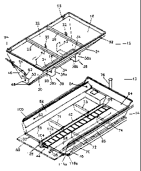
FIGS. 1, 2 and 3 illustrate an exemplary dump truck apparatus 10 for
converting a
vehicle such as a pickup truck into a dump truck or spreader truck. The
apparatus 10 may
also be installed directly on the long sills of a truck chassis. FIG. 1 is a
rear perspective
view of the apparatus 10, while FIGS. 2 and 3 provide rear and side views
respectively.
The apparatus 10 comprises two components, namely a dump body unit 14 and a
removable hopper 12. The dump body unit 14 is intended to be installed in the
bed of the
vehicle for conversion of the vehicle into a dump truck. It will be
appreciated that only the
dump body unit 14 portion of the apparatus 10 is used when it is desired to
configure the
vehicle for use as a dump truck. The hopper 12 is attached to the installed
dump body unit
14 only when it is desired to alternatively configure the vehicle for use as a
spreader truck.
The apparatus 10 thus has two modes of operation: dump truck mode (involving
use of
only the dump body unit 14) and spreader truck mode (involving use of both the
dump
body unit 14 and the hopper 12).
Dump body unit 14 consists of a dump body 100 pivotally interconnected with a
main frame 70. The dump body 100 is for holding and dumping materials, while
the main
frame 70 attaches to a vehicle such as a pickup truck to install the
apparatus. The main
-7-
CA 02360738 2001-10-31
frame 70 also supports the dump body 100 when it is in a lowered or hauling
position.
Also included in dump body unit 14 is a hoist 138 (FIG. 3) for raising and
lowering the
dump body 100.
Dump body 100 includes a generaily rectangular bed 56, side walls 60 and 62
and
a front wall 64. A removable tailgate 80 (shown in ghost outline in FIG. 1) is
optionally
attached to the rear of the body 100, as will be described. The bed 56 is
substantially flat
and has a centrally disposed longitudinal channel 40. The channel 40 is
rectangular and
contains an embedded conveyor 44 for feeding material back towards the rear of
the
body. A pair of L-shaped reinforcing plates 103 and 105 at the rear of the
dump body 100
(visible in FIG. 1 but omitted from FIG. 2 for clarity) help to attach the
conveyor 44 to the
bed 56.
The dump body 100 includes a pair of brackets 76 and 77 for pivotally
interconnecting the dump body 100 with the main frame 70 which protrude
downwardly
from the underside of the bed 56 at its rear comers (FIG. 2). Each of the
brackets 76 and
77 has a transverse circular aperture located distally from the bed 56. These
apertures
are coaxial and cooperatively hold a pivot pin 118 which is transverse to the
dump body's
length and capable of rotation within the apertures. The length of the pivot
pin 118 is
approximately the same as the width of the main frame 70. Four buttresses 71,
72, 73,
and 74 protrude downwardly from the underside of bed 56 (FIG. 1). The
orientation of the
buttresses is transverse to the length of the dump body 100. Buttresses 71 and
72 are
substantially coplanar and are closer the to rear of the body 100 than
supports 73 and 74,
which are also substantially coplanar. The four buttresses 71, 72, 73 and 74
serve to
distribute the weight of the dump body 100 (and any contained materials) onto
the main
frame 70 when the body 100 is in a lowered position. As well, these buttresses
provide
structural integrity to the dump body 100 and help to secure the conveyor 44
to the body
100.
Dump body 100 includes a set of four screw eyes 82, 84, 86 and 88 (FIGS. 1-3)
for
attaching the hopper 12 to the dump body unit 14 when the apparatus 10 is used
in its
spreader truck mode. Screw eyes 82 and 84, which are best seen in FIG. 1,
protrude
-8-
CA 02360738 2001-10-31
upwardly and inwardly from the side wall 62 of the body 100 near its top edge,
with the
first screw eye 82 being proximate to optional tailgate 80 and the second
screw eye 84
being proximate to the front wall 64. The screw eyes 86 and 88 protrude
inwardly from the
opposite side wall 60 in a symmetric arrangement.
One edge of the optional tailgate 80 of the dump body 100 is pivotally
attached to
the rear edge of the bed 56 along an axis that is transverse to the length of
the dump body
14. The tailgate 80 may be pivoted upwardly around this axis and latched in
its raised
position to form a substantially vertical rear wall of the dump body 14,
during hauling of
materials for example. The tailgate is capable of being removed from the dump
body 100,
during the dumping of materials for example. Tailgate 80 is omitted from FIGS.
2 and 3 for
clarity.
As best seen in FIG. 4 (which illustrates in front perspective view the main
frame
70, the conveyor 44 portion of the dump body 100, and the hoist 138), main
frame 70 is a
rectangular frame having an extent similar to that of the dump body bed 56.
The rear
section of the frame 70 has a set of six rearwardly protruding brackets 116a,
116b, 116c,
116d, 116e and 116f (FIG. 2). Each of the brackets 116 has a circular aperture
transverse to the length of the frame 70. The apertures are coaxial and
fixedly retain the
pivot pin 118. Pivot pin 118 thus defines a pivotal axis about which the dump
body 100
may rotate in relation to the main frame 70 during raising of the body 100 to
its inclined
"dumping" position or lowering of the body to its "hauling" position. A motor
mounting plate
126 near the front of the frame 70 is suitable for mounting an optional small
engine. This
optional small engine may provide an altemative power source (instead of the
vehicle's
engine) for driving the hoist 138 and the conveyor 44, as will be described.
The hoist 138 is a conventional hydraulic hoist including a hydraulic cylinder
78 and
a hydraulic tank 142. The hoist 138 is disposed at the front of the dump body
unit 14 and
is pivotally interconnected with the front of main frame 70 and the front of
dump body 100.
Extension of the cylinder 78 results in rotation of the dump body 100 about
pivot pin 118
away from main frame 70 to incline body 100 to its raised or dumping position,
while
retraction of the cylinder 78 results in rotation of the dump body 100 about
pin 118
-9-
CA 02360738 2001-10-31
towards frame 70 to decline the body to its lowered or hauling position. The
hoist 138 may
be powered by way of a Power Take-Off (PTO) of the vehicle, which, as known in
the art,
is an interface from a vehicle's engine to drive hydraulic systems.
Altematively, in the
event that the vehicle is not equipped with a PTO feature, the hoist 138 may
be powered
by an optional small engine that may be mounted to mounting plate 126.
An integrated conveyor 44 is housed within the channel 40 in the bed 56 of the
body 100. As may best be seen in FIGS. 1, 3 and 4, the conveyor mechanism 44
includes
two conveyor side walls 122 and 124. Two longitudinally disposed and laterally
spaced
parallel endless chains 110 and 112 engage front and rear sprockets 108, 104
and 106,
102 respectively. A plurality of slats 120 for moving materials extends
between the chains
110 and 112.
Rear sprockets 102 and 104 are coaxial and are fixedly mounted to a rear axle
130
that is transverse to the length of the conveyor 44. The ends of axle 130 are
mounted by
way of bearings 134 and 136 to conveyor side walls 122 and 124 respectively so
as to
facilitate rotation of the axle 130. A hydraulic motor 128 is mounted to the
conveyor wall
124, with its drive mechanism being connected to the axle 130 for driving the
conveyor 44.
Motor 128 is capable of further driving a spreader device that may be mounted
near the
rear of the conveyor 44 when the vehicle is used as a spreader truck, as will
be described.
The motor 128 may be powered by way of the Power Take-Off (PTO) of the vehicle
or by
the optional small engine that may be mounted to mounting plate 126.
Front sprockets 106 and 108 are also coaxial and are fixedly mounted to a
front
axle 132, which is similarly mounted in a transverse orientation between side
walls 122
and 123 by way of bearings so as to permit rotation of the axle and sprockets.
Only one of
the bearings 140 is visible in FIG. 4.
The main frame may include an electrical-hydraulic interface 148 (FIG. 4)
otherwise
known as a control junction box. As known by those skilled in the art, the
interface 148 is
capable of receiving signals from electrical controls and adjusting hydraulic
control valves
in response thereto to provide electrical control of hydraulically powered
devices such as
the hoist 138 and conveyor 144. The electrical controls are typically located
in the
-10-
CA 02360738 2001-10-31
vehicle's cab for convenience and are interconnected by electrical wires to
interface 148.
Hydraulic lines interconnect the interface 148 with the hoist 138 and the
motor 128 which
drives the conveyor 44.
Hopper 12 (FIGS. 1-3) is generally V-shaped in cross-section and has a front
and
rear wall 18 and 20, respectively, as well as first and second side walls 22
and 24. The
front wall 18 of the hopper 12 is sloped, with its bottom edge being more
proximate to the
opposing rear wall 20 than its top edge (as best seen in FIG. 3). Rear wall 20
is
substantially vertical. The hopper 12 has a longitudinal rectangular aperture
16 at its base.
A downwardly-protruding lip 34 extends from the bottom edge of the side walls
22 and 24
and from the base of the front wall 18 around three sides of the aperture 16.
The outer
perimeter of the lip 34 is suitably sized for being received by the channel 40
in dump body
100 in a secure fit when the hopper 12 is attached to the dump body 100 for
use of the
apparatus 10 in the spreader truck mode.
A pair of spars 26 and 28 extends between the interior top edges of side walls
22
and 24 to provide structural integrity to the hopper 12. The spars 26 and 28
are also for
supporting a cover (not shown) that may optionally be laid over the top of
hopper 12.
Affixed to each spar 26 and 28 is a loop 30 and 32 which may be used for
attaching hooks
to lift the hopper 12 during conversion to or from spreader truck mode, or for
suspended
storage of the hopper 12.
As can best be seen in FIGS. 1 and 3, two longitudinally spaced right-angle
brackets 36 and 38 are attached to the side wall 24 of the hopper 12 to
provide a
supporting base for the hopper when it is in place within the dump body unit
14. The angle
brackets 36 and 38 also provide structural support to the side wall 24. The
lower end of
each angle bracket is attached at the base of the wall 24, while the upper end
of each
bracket is attached to the side wall 24 at a point that is approximately half
the distance
between the wall's top and bottom edges. The angle brackets are oriented so
that their
lower members 36b and 38b are substantially horizontal, to promote uniform
contact
between the underside of the members 36b and 38b and the flat dump body bed 56
when
the hopper portion 12 is in place within dump body 100 during use of the
apparatus 10 in
-11-
CA 02360738 2001-10-31
its spreader truck mode. The upper members 36a and 38a of the angle brackets
may be
vertical. A second pair of right-angle brackets 42 and 43 is attached to the
opposing side
wall 22 in a symmetric arrangement.
A conventional levered door mechanism 46 (FIGS. 1-3) for controlling the
release
of material from the hopper 12 is attached to the exterior side of the
hopper's rear wall 20.
The door mechanism 46 includes a door plate 50 slidably received between a
pair of
vertical guide rails 48 attached to the base of the rear wall 20. The plate 50
is pivotally
attached to one end of a first link arm 52. The other end of arm 52 is
pivotally
interconnected to an end of a second link arm 54. Link arm 54 is pivotally
connected
between its two ends to the rear wall 20 of the hopper 12. Downward pressure
on the free
end of link arm 54 results in the door plate 50 being raised.
A pair of screw eyes 90 and 92 (FIG. 1) for attaching the hopper to the dump
body
unit 14 protrude outwardly from the side wall 24 of the hopper 12 near its top
edge, with
the first screw eye 90 being proximate to the rear wall 20 and the second
screw eye 92
being proximate to the front wall 18. A second pair of screw eyes 94 and 96
protrudes
outwardly from the opposite side wall 22 in a symmetric arrangement.
The operation of the apparatus 10 occurs in one of two modes: dump truck mode
and spreader truck mode. Use of the apparatus 10 in dump truck mode is
illustrated in
FIGS. 5 and 6, while use of the apparatus in spreader truck mode is
illustrated in FIGS. 7
and 8.
Referring first to FIGS. 5 and 6, the figures illustrate the dump body unit 14
installed in the bed of a pickup truck. Installation may be achieved by
bolting the main
frame 70 of the dump body unit 14 to the truck body or chassis. The vehicle's
PTO is
hydraulically interconnected with the electrical-hydraulic interface 148.
Altematively, if the
vehicle lacks a PTO, a small engine that is attached to mounting plate 126 is
hydraulically
interconnected with the interface 148. Electrical controls in the cab of the
vehicle for
controlling the hoist and conveyor of apparatus 10 are interconnected with
electrical-
hydraulic interface 148 by way of electrical wires. It is noted that
attachment of the dump
body unit 14 to the pickup truck, including the requisite attachment of
hydraulic lines and
-12-
CA 02360738 2001-10-31
electrical wires, is done oniy upon this initial installation of the apparatus
10. The pickup
truck's standard tailgate (if any) may be removed prior to installation.
Prior to any loading of materials into the dump body 100, a removable conveyor
cover 144 (FIG. 5) is attached over the top of the channel 40 in dump body bed
56 so as
to prevent any material from entering the conveyor mechanism 44. The cover 144
is
attached by way of screws or similar removable fasteners. Altematively, the
cover may be
slidably received in opposing grooves (not shown) which run the length of the
interior of
conveyor walls 122 and 124.
With the dump body 100 in its lowered or hauling position, the body 100 is
filled
with material 146 to be transported. The tailgate 80 may then be raised and
latched to
contain the material 146 during transportation. Hauling of the material 146
may then
occur. When it is desired to unload the material 146, the tailgate 80 is first
either lowered
or removed. Next, the PTO is engaged or the small engine started and the
electrical
controls in the cab are used to activate the hoist 138. Engagement of the
hoist 138 causes
the cylinder 78 to extend, which in tum causes the dump body 100 to rotate
about pivot
pin 118 away from the main frame 70 until the dump body 100 is raised to its
dumping
position (FIG. 6), and the material 146 may thus be rapidly unloaded with the
assistance
of gravity.
Use of the apparatus 10 in its spreader truck mode is illustrated in FIGS. 7
and 8.
In this mode, the dump body unit 14 remains installed in the pickup truck bed
as it was in
the dump truck mode. Any residual material 146 is removed from the body 100.
The cover
144 is removed from the channel 40 to expose the conveyor 44. Next, the hopper
12 is
lowered into the dump body 100 so that the downwardly protruding lip 34 of the
hopper 12
is received in the channel 40. This serves to mate the hopper 12 with the body
100 and
positions the aperture 16 directly over the conveyor 44. Contact between the
lip 34 and
the walls of the channel 40 also reduces the likelihood of lateral or forward
shifting of the
hopper 12 during use. The weight of the lowered hopper 12 is supported
primarily by the
underside of angle brackets 36, 38, 42 and 43, which contact the surface of
the dump
body bed 56. It will be appreciated that, since the hopper 12 does not include
an integral
-13-
CA 02360738 2001-10-31
conveyor, the weight of the hopper 12 may be sufficiently small that a single
person may
be capable of lowering the hopper 12 into the dump body 100 as described.
The lowered hopper 12 is then anchored to the dump body 100 through connection
of the outwardly protruding screw eyes 90, 92, 94 and 96 of hopper 12 to the
inwardly
protruding screw eyes 86, 88, 82 and 84 (respectively) of the dump body 100.
This
interconnection is by way of tumbuckles 150, 152, 154 and 156 respectively,
which are
tightened to secure the hopper 12 to the dump body 100.
A conventional spreader unit 160 is attached near the rear of the conveyor 44.
The
spreader unit 160 may include a chute 162 that is attached below the end of
the conveyor
44 in order to funnel materials 146 exiting from the conveyor 44 onto the
spreader 160.
The spreader 160 is interconnected with the drive mechanism of the hydraulic
motor 128
so that motor 128, which drives the conveyor, can additionally drive the
spreader 160.
With the dump body 100 being maintained in its lowered position during use of
the
apparatus in its spreader truck mode, the hopper 12 is filled with material
146 to be
dispersed. The position of door 50 of hopper door mechanism 46 (FIGS. 1-3) may
be
adjusted through manipulation of the free end of link arm 54 so that a desired
rate of
release of the material 146 is achieved. To spread materials, the motor 128 is
engaged
using the electrical controls in the cab of the vehicle, so that both the
conveyor 44 and the
spreader unit 160 are activated. As a result, material 146 contained in the
hopper 12,
which is fed by gravity onto the moving conveyor 44, is conveyed rearwardly
onto the
spreader 160 for dispersion.
It will be appreciated that, conveniently, conversion of the apparatus from
its dump
truck mode to its spreader truck mode does not require the attachment of
electric wires or
hydraulic lines.
Conversion of the apparatus 10 back to its dump truck mode entails removal of
the
hopper 12 from the dump body unit 14 (with the associated detachment of
tumbuckles
150, 152, 154 and 156), detachment of the spreader unit 160, and the covering
of
-14-
CA 02360738 2001-10-31
conveyor 44 with cover 144. Again, no interconnection of electric wires or
hydraulic lines
is required.
As will be appreciated by those skilled in the art, modifications to the above-
described embodiment can be made without departing from the essence of the
invention.
For example, use of the apparatus 10 in its spreader truck mode does not
necessarily
require the attachment of a spreader 160. Absent a spreader, materials exiting
the
conveyor 44 may effectively be spread over the ground surface underlying the
vehicle
through scattering which results from the impact of the materials falling to
the ground.
When a spreader is in fact utilized, the spreader may be powered by a motor
that is
different from the motor which drives the conveyor unit.
The hopper 12 does not necessarily have a door mechanism 46 for controlling
the
rate of release of contained materials, but may instead have an aperture for a
fixed rate of
release. Also, front wall 18 is not necessarily sloped.
The main frame 70 may comprise a truck chassis. In this case, attachment of
the
main frame 70 to the vehicle is inherent in the fact that the chassis forms
part of a truck.
While not preferred, channel 40 could be omitted in which case the conveyor 44
would be mounted onto the bed 56 of dump body 100 rather than within channel
40. In
such instance, cover 144 would extend upwardly into the dump body 100 to cover
the
conveyor 44 when the apparatus is used as a dump truck. The brackets of the
hopper 12
would also need to be reconfigured to position the lip 34 of the hopper 12
around the
conveyor.
Also, it is not necessary for the conveyor to be covered during use of the
vehicle as
a dump truck. Use of a conveyor cover may be deemed unnecessary during hauling
of
some rigid types of materials (e.g. sheets of plywood) because the materials
may be too
large to fall into the conveyor. Altematively, in the case of granular or
loose materials, the
amount of material that may fall into the conveyor may be deemed negligible
with respect
to the size of the overall load, thus the added step of covering the conveyor
may not be
justified.
-15-
CA 02360738 2001-10-31
Other modifications will be apparent to those skilled in the art and,
therefore, the
invention is defined in the claims.
-16-