Language selection

Search

Patent 2361320 Summary

Third-party information liability

Some of the information on this Web page has been provided by external sources. The Government of Canada is not responsible for the accuracy, reliability or currency of the information supplied by external sources. Users wishing to rely upon this information should consult directly with the source of the information. Content provided by external sources is not subject to official languages, privacy and accessibility requirements.

Claims and Abstract availability

Any discrepancies in the text and image of the Claims and Abstract are due to differing posting times. Text of the Claims and Abstract are posted:

  • At the time the application is open to public inspection;
  • At the time of issue of the patent (grant).
(12) Patent: (11) CA 2361320
(54) English Title: IMPROVEMENT IN THE ASSEMBLY STRUCTURE OF A HIGH DOOR
(54) French Title: AMELIORATION APPORTEE A LA STRUCTURE D'ASSEMBLAGE D'UNE PORTE HAUTE
Status: Term Expired - Post Grant Beyond Limit
Bibliographic Data
(51) International Patent Classification (IPC):
  • E06B 3/70 (2006.01)
  • E06B 3/82 (2006.01)
(72) Inventors :
  • WANG CHEN, KUEI-YUNG (Taiwan, Province of China)
(73) Owners :
  • NAN YA PLASTICS CORPORATION
(71) Applicants :
  • NAN YA PLASTICS CORPORATION (Taiwan, Province of China)
(74) Agent: SMART & BIGGAR LP
(74) Associate agent:
(45) Issued: 2009-01-13
(22) Filed Date: 2001-11-07
(41) Open to Public Inspection: 2003-05-07
Examination requested: 2006-11-02
Availability of licence: N/A
Dedicated to the Public: N/A
(25) Language of filing: English

Patent Cooperation Treaty (PCT): No

(30) Application Priority Data: None

Abstracts

English Abstract

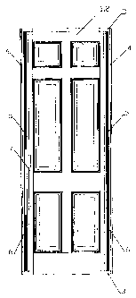
The invention relates to an improvement in the assembly structure of a high door. This improvement is characterized by the inner side of an upper longer region (above the handle) of the left edge-sealing angle bar and the inner side of a lower shorter region (below the handle) of the left edge-sealing angle bar being inlaid with two U-shaped reinforcing irons the length of which corresponds to the length of the two regions. A first wood strip the length of which is slightly shorter than that of the left edge-sealing angle bar is inserted into the U--shape of the two U-shaped reinforcing irons, then joined, by a nail gun and an adhesive, to a second wood strip. The handle position is then inlaid with a reinforcing angle bar. The inner side of the right edge-sealing angle bar is inlaid with a U-shaped reinforcing iron the length of which is slightly shorter than that of the right edge-sealing angle bar. A third wood strip with a length corresponding to that of the U-shaped reinforcing iron is inserted therein and joined, by a nail gun and adhesive, to a fourth wood strip. The structure is coated with an adhesive and press-assembled with two contoured door skins. After assembly, a hole is drilled in the bottom edge-sealing angle bar and the hollow core formed by the two contoured door skins is filled up with ammonium polyester foamed plastic to form a high door structure which will not bend or deform.


French Abstract

L'invention concerne une amélioration apportée à la structure d'assemblage d'une porte haute. Cette amélioration est caractérisée par le pan intérieur d'une zone supérieure relativement longue (au-dessus de la poignée) de la cornière du scellement du bord gauche et le pan intérieur d'une zone inférieure relativement courte (en dessous de la poignée) de la cornière du scellement du bord gauche étant incrusté avec deux fers de renfort en U dont la longueur correspond à celle des deux zones. Une première bande de bois dont la longueur est légèrement plus courte que celle de la cornière du scellement du bord gauche est insérée dans la forme en U des deux fers de renfort en U, puis jointe, par un pistolet goujonneur et un adhésif à une seconde bande de bois. La position de la poignée est ensuite incrustée avec une cornière de renfort. Le pan intérieur de la cornière du scellement du bord droit est incrustée dans un fer de renfort en U dont la longueur est légèrement plus courte que celle de la cornière du scellement du bord droit. Une troisième bande de bois dont la longueur correspond à celle du fer de renfort en U y est insérée et jointe, par un pistolet goujonneur et un adhésif à une quatrième bande de bois. La structure est revêtue d'un adhésif et assemblée avec deux revêtements de porte profilés. Après assemblage un trou est perforé dans la cornière de scellement latéral en bas et le trou au milieu au formé par les deux revêtements de porte profilés est rempli de mousse de plastique en polyester d'ammonium pour former une structure de porte haute qui ne se courbera pas ni ne se déformera.

Claims

Note: Claims are shown in the official language in which they were submitted.


The embodiments of the invention in which an exclusive property or privilege
is claimed are
defined as follows:
1. An improved high door structure, wherein the door structure comprises two
contoured door skins, a top edge-sealing angle bar, a bottom edge-sealing
angle bar, a left
edge-sealing angle bar, and a right edge-sealing angle bar, and wherein the
contoured door
skins are integrally molded flush-edged structures which are positioned by
flange ribs of the
left edge-sealing angle bar and the right edge-sealing angle bar, and wherein
the top edge-
sealing angle bar and the bottom edge-sealing angle bar are positioned at
milled notches at
the top and the bottom ends of the left edge-sealing angle bar and the right
edge-sealing angle
bar, and wherein the improvement comprises:
an inner side of an upper longer region of the left edge-sealing angle bar and
an inner
side of a lower shorter region of the left edge-sealing angle bar being
respectively inlaid with
a U-shaped reinforcing iron having a length corresponding to each length of
the upper and
lower regions; a first wood strip having a length slightly shorter than that
of the left edge-
sealing angle bar being inserted into the U-shape of the two U-shaped
reinforcing irons and
joined, by a nail gun and an adhesive, to a second wood strip, a handle
position being inlaid
with a reinforcing angle bar; and
an inner side of the right edge-sealing angle bar being inlaid with a U-shaped
reinforcing iron having a length slightly shorter than that of the right edge-
sealing angle bar, a
third wood strip having a length which corresponds to the U-shaped reinforcing
iron being
inserted therein and joined, by the nail gun and adhesive, to a fourth wood
strip,
and wherein the resulting structure is coated with an adhesive and then press-
assembled with two contoured door skins, and wherein, after assembly, a hole
is drilled in the
bottom edge-sealing angle bar and filled with ammonium polyester foamed
plastic to form
the high door structure.
2. The improved high door structure as defined in claim 1, wherein the
material
of the contoured door skin is sheet molding compound taken from the group
comprising
strengthened glass fiber, wood fiber, steel, and natural wood.
7

3. The improved high door structure as defined in claim 2, wherein the
material
of the edge-sealing angle bar is taken from the group comprising, PVC profile,
PVC foam
profile, wood, steel, and ejected plastic.
4. The improved high door structure as defined in claim 2, wherein the surface
of
the contoured door skin is smooth or simulated wood grain.
5. The improved high door structure as defined in claim 4, wherein the depth
of
the simulated wood grain is about 0.05 to 0.2 mm.
6. The improved high door structure as defined in claim 5, wherein the
material
of the edge-sealing angle bar is taken from the group comprising PVC profile,
PVC foam
profile, wood, steel, and ejected plastic.
7. The improved high door structure as defined in claim 5, wherein the
contoured
door skin is a flat surface or comprising 3 , 4 or 6 panels.
8. The improved high door structure as defined in claim 7, wherein the
material
of the edge-sealing angle bar is taken from the group comprising PVC profile,
PVC foam
profile, wood, steel, and ejected plastic.
8

Description

Note: Descriptions are shown in the official language in which they were submitted.


CA 02361320 2006-11-28
IMPROVEMENT IN THE ASSEMBLY STRUCTURE OF A HIGH DOOR
BACKGROUND OF THE INVENTION
Field of Invention
The invention relates to an improvement in the assembly structure of a high
door through the
use of multiple reinforcing structures such as a U-shaped reinforcing iron and
a wood strip to
prevent the door from bending and deforming due to its height.
Description of the Related Prior Art
Referring to the traditional doors in the market, there are roughly two kinds
of doors: one
door with an ordinary height of about 200 cm (6 ft 8 in); and another high
door with a height
of about 240 cm (8 ft). In general, the assembly structure of the high door is
not strong
enough to support the weight of itself, resulting in bending and deformation
such that the
door may become unsuitable for installation or unsafe. Reinforcing the
assembly structure of
the high door would therefore be of benefit.
SUMMARY OF THIS INVENTION
The main purpose of this invention is to reinforce the assembly structure of a
high door to
prevent the high door from bending and deforming. This is accomplished by
inlaying a U-
shaped reinforcing iron whereby a first wood strip is inserted in the U-shape
of the
reinforcing iron and a second wood strip is then closely joined to the first
wood strip by a nail
gun and adhesive to improve the assembly structure and the rigidity of the
high door.
The other purpose of this invention is to disclose an assembly structure for a
high door
comprising two contoured door skins, a top edge-sealing angle bar, a bottom
edge-sealing
angle bar, a left edge-sealing angle bar, and a right edge-sealing angle bar.
The contoured
door skin is an integrally molded flush-edged structure which is positioned at
the flange ribs
of the left edge-sealing angle bar and the right edge-sealing angle bar. The
top edge-sealing
angle bar and the bottom edge-sealing angle bar are positioned using milled
notches formed
at the top and bottom ends of the left edge-sealing angle bar and the right
edge-sealing angle
bar.
I

CA 02361320 2006-11-28
This invention is characterized by the inner side of the upper longer region
(above the handle)
of the left edge-sealing angle bar and the inner side of the lower shorter
region (below the
handle) of the left edge-sealing angle bar being connected with two U-shaped
reinforcing
irons the length of which corresponds to each length of the upper and lower
regions. A first
wood strip with a length slightly shorter than that of the left edge-sealing
angle bar is inserted
into the U-shape of the U-shaped reinforcing irons, and, using a nail gun and
adhesive, a
second wood strip is closely joined together to the first wood strip. The
inner side of the right
edge-sealing angle bar is connected to a U-shaped reinforcing iron the length
of which is
slightly shorter than that of the right edge-sealing angle bar, then a third
wood strip with a
length corresponding to that of the U-shaped reinforcing iron is inserted
therein and using a
nail gun and adhesive, a fourth wood strip is closely joined to the third wood
strip. The
structure is then coated with an adhesive and press-assembled with two
contoured door skins.
After assembly, a holed is drilled in the bottom edge-sealing angle bar and
the hollow core
formed by the two contoured door skins is filled with ammonium polyester
foamed plastic to
form a high door structure which will not bend or deform.
BRIEF DESCRIPTION OF THE DRAWINGS
The invention which now be described with reference to the drawings in which:
Fig. 1 is a drawing of the assembled high door structure in accordance with
the
present invention;
Fig. 2 is an exploded view of the door structure of Fig. 1;
Fig. 3 is a horizontal cross-section drawing of the door assembly of Fig. 1;
Fig. 4 is a vertical cross-section drawing of the door assembly of Fig. 1;
Fig. 5 is a drawing of the reinforced structure of the door assembly of Fig.
1; and
Fig. 6 is an exploded cross-sectional drawing depicting the assembly procedure
of a
reinforced structure of the door assembly of Fig. 1.
2

CA 02361320 2006-11-28
DETAILED DESCRIPTION OF THE PREFERRED EMBODIMENT
Symbols of the drawings are explained as follows:
1, 2: skin of contoured door
1-1: top skin
2-1: bottom skin
3: top and bottom edge-sealing angle bar
3-1: top edge-sealing angle bar
3-2: bottom edge-sealing angle bar
4: left and right edge-sealing angle bar
4-1: right edge-sealing angle bar
4-2: left edge-sealing angle bar
4-3: flange rib of the left and right edge-sealing angle bar
4-4: milled notches at the top and bottom ends of the left and right edge-
sealing angle bar
5: left and right reinforcing angle bar
5-1: first, third wood strips
5-2: second, fourth wood strips
6: left and right U-shaped reinforcing iron
6-1: left longer U-shaped reinforcing iron
6-2: left shorter U-shaped reinforcing iron
6-3: right U-shaped reinforcing iron
7: handle area reinforcing angle bar
8: ammonium polyester foamed plastic
This invention improves the assembled structure of a high door through the use
of multiple
reinforcing structures such as a U-shaped reinforcing iron and a wood strip to
advantageously
prevent the high door from bending and deforming due to its height. To assist
in
understanding the invention, the invention will now be described with
reference to the
drawings.
Referring to Fig. 1 and Fig. 2, the assembly structure of the high door of
this invention
comprises two contoured door skins 1 or 2, a top edge-sealing angle bar 3-1, a
bottom edge-
sealing angle bar 3-2, a left edge-sealing angle bar 4-2, a right edge-sealing
angle bar 4-1, a
3

CA 02361320 2006-11-28
couple of left and right wood strips 5-1, a couple of left and right wood
strips 5-2, a left
longer U-shaped reinforcing iron 6-1, a left shorter U-shaped reinforcing iron
6-2, a right U-
shaped reinforcing iron 6-3, and a handle area reinforcing angle bar 7.
The thickness of the contoured door skin 1 or 2 of the present invention is
about 1 to 4 mm,
of which the material can be strengthened glass fiber, wood fiber, steel, or
natural wood. The
outer surface of the contoured door skin is provided with a smooth surface or
a simulated
wood grain. The depth of the simulated wood grain is about 0.05 to 0.2 mm. The
contoured
door skins 1 or 2 can be a flat surface or comprised of three, four or six
panels. The inside
surface of the contoured door skins 1 or 2 are rough to ensure a strong bond
when glued to
the door structure as will be discussed below. The four edges of the contoured
door skins 1
or 2 are designed to be flush with and adhered to the top edge-sealing angle
bar 3-1, the
bottom edge-sealing angle bar 3-2, the left edge-sealing angle bar 4-2, and
the right edge-
sealing angle bar 4-1. The material of the top edge-sealing angle bar 3-1 and
bottom edge-
sealing angle bar 3-2 can be PVC profile, PVC foam profile, wood, steel, or
ejected plastic.
Referring to Fig. 2, the assembly procedure of the high door of the present
invention is as
follows: the door skins 1 or 2, the top edge-sealing angle bar 3-1, the bottom
edge-sealing
angle bar 3-2, the left edge-sealing angle bar 4-2, and the right edge-sealing
angle bar 4-1 are
glued and assembled. The contoured door skins 1 or 2 are molded flush-edged
structures
which are positioned (see Fig. 3 and Fig. 4) at the flange ribs 4-3 of the
left edge-sealing
angle bar 4-2 and the right edge-sealing angle bar 4-1. The top edge-sealing
angle bar 3-1 and
the bottom edge-sealing angle bar 3-2 are positioned in the milled notches 4-4
at the top and
the bottom ends of the left edge-sealing angle bar 4-2 and the right edge-
sealing angle
bar 4-1.
In addition, the inner side of the left edge-sealing angle bar 4-2 and the
inner side of the right
edge-sealing angle bar 4-1 are inlaid with a reinforcing structure (see Fig.
5) comprising: a
couple of left and the right wood strips 5-1, a couple of left and the right
wood strips 5-2, a
left longer U-shaped reinforcing iron 6-1, a left shorter U-shaped reinforcing
iron 6-2, a right
U-shaped reinforcing iron 6-3, and a handle area reinforcing angle bar 7.
After completion of
the assembly, the internal surfaces of the two contoured door skins 1 or 2
form a sealed space
therebetween. A hole is then drilled into the bottom edge-sealing angle bar 3-
2 and the space
4

CA 02361320 2006-11-28
between the internal surfaces of the two contoured door skins 1 or 2 is filled
with ammonium
polyester foamed plastic 8 to form the high door structure which will not bend
or deform.
Referring to Fig. 2, Fig. 3, Fig. 4, Fig. 5, and Fig. 6, to reinforce the
strength of the high door,
the preferred embodiment of the high door structure includes left and right
wood strips 5-1
which are inserted into the U-shape of left longer U-shaped reinforcing iron 6-
1, left shorter
U-shape reinforcing iron 6-2, and right U-shaped reinforcing iron 6-3
respectively.
Therefore, the high door structure of this invention comprises members of two
contoured
door skins 1 or 2, a top edge-sealing angle bar 3-1, a bottom edge-sealing
angle bar 3-2, a left
edge-sealing angle bar 4-2, and a right edge-sealing angle bar 4-1. The
contoured door skins
1 or 2 are integrally molded flush-edged structure which are positioned at
flange ribs 4-3 of
the left edge-sealing angle bar 4-2 and the right edge-sealing angle bar 4-1.
The top edge-
sealing angle bar 3-1 and the bottom edge-sealing angle bar 3-2 are positioned
at milled
notches 4-4 at the top and the bottom ends of the left edge-sealing angle bar
4-2 and the right
edge-sealing angle bar 4-1. In addition, the inner side of the upper longer
region (above the
handle) of the left edge-sealing angle bar 4-2 and the inner side of the lower
shorter region
(below the handle) of the left edge-sealing angle bar 4-2 are respectively
connected with a
left longer U-shaped reinforcing iron 6-1 and a left shorter U-shaped
reinforcing iron 6-2,
each length corresponding to the length of the two regions. A first wood strip
5-1 with a
length slightly shorter than that of the left edge-sealing angle bar 4-2 is
inserted into the U-
shape of the left longer U-shaped reinforcing iron 6-1 and the left shorter U-
shape reinforcing
iron 6-2. Using a nail gun and adhesive a second wood strip 5-2 is joined
together with the
first wood strip 5-1, and at a handle area of the second wood strip 5-2 a
handle area
reinforcing angle bar 7 is then joined to the wood strip 5-2 to reinforce the
strength of a
handle to be installed (not shown). The inner side of the right edge-sealing
angle bar 4-1 is
connected with a U-shaped reinforcing iron 6-3 the length of which is slightly
shorter than
that of the right edge-sealing angle bar 4-1, then a third wood strip 5-1 with
a length
corresponding to that of the U-shape reinforcing iron 6-3 is inserted therein,
and, using a nail
gun and adhesive, a fourth wood strip 5-2 is joined together with the third
wood strip 5-1.
Thereafter, the assembled structure is coated with an adhesive and press-
assembled with the

CA 02361320 2006-11-28
two contoured door skins lor 2. After assembly, a hole is drilled in the
bottom edge-sealing
angle bar 3-2 and the hollow core formed by the two contoured door skins 1 or
2 is filled up
with ammonium polyester foamed plastic 8 to form the high door structure
having reinforced
strength.
The high door will not bend or deform through the use of the left longer U-
shaped reinforcing
iron 6-1, the left shorter U-shaped reinforcing iron 6-2, the right U-shaped
reinforcing
iron 6-3, and wood strips 5-1 and 5-2 which form the unique reinforced door
structure of the
present invention.
6

Representative Drawing
A single figure which represents the drawing illustrating the invention.
Administrative Status

2024-08-01:As part of the Next Generation Patents (NGP) transition, the Canadian Patents Database (CPD) now contains a more detailed Event History, which replicates the Event Log of our new back-office solution.

Please note that "Inactive:" events refers to events no longer in use in our new back-office solution.

For a clearer understanding of the status of the application/patent presented on this page, the site Disclaimer , as well as the definitions for Patent , Event History , Maintenance Fee  and Payment History  should be consulted.

Event History

Description Date
Inactive: Expired (new Act pat) 2021-11-08
Inactive: Office letter 2019-11-13
Revocation of Agent Requirements Determined Compliant 2019-11-13
Appointment of Agent Requirements Determined Compliant 2019-11-13
Common Representative Appointed 2019-10-30
Appointment of Agent Request 2019-10-10
Revocation of Agent Request 2019-10-10
Change of Address or Method of Correspondence Request Received 2018-01-09
Grant by Issuance 2009-01-13
Inactive: Cover page published 2009-01-12
Pre-grant 2008-09-23
Inactive: Final fee received 2008-09-23
Notice of Allowance is Issued 2008-05-08
Letter Sent 2008-05-08
Notice of Allowance is Issued 2008-05-08
Inactive: Approved for allowance (AFA) 2008-04-28
Amendment Received - Voluntary Amendment 2006-11-28
Letter Sent 2006-11-16
Request for Examination Requirements Determined Compliant 2006-11-02
Request for Examination Received 2006-11-02
All Requirements for Examination Determined Compliant 2006-11-02
Amendment Received - Voluntary Amendment 2006-11-02
Inactive: IPC from MCD 2006-03-12
Application Published (Open to Public Inspection) 2003-05-07
Inactive: Cover page published 2003-05-06
Inactive: Filing certificate - No RFE (English) 2002-02-19
Inactive: First IPC assigned 2002-01-17
Inactive: Filing certificate correction 2001-12-19
Inactive: Correspondence - Transfer 2001-12-19
Inactive: Filing certificate - No RFE (English) 2001-11-23
Filing Requirements Determined Compliant 2001-11-23
Letter Sent 2001-11-23
Application Received - Regular National 2001-11-21

Abandonment History

There is no abandonment history.

Maintenance Fee

The last payment was received on 2008-10-22

Note : If the full payment has not been received on or before the date indicated, a further fee may be required which may be one of the following

  • the reinstatement fee;
  • the late payment fee; or
  • additional fee to reverse deemed expiry.

Please refer to the CIPO Patent Fees web page to see all current fee amounts.

Owners on Record

Note: Records showing the ownership history in alphabetical order.

Current Owners on Record
NAN YA PLASTICS CORPORATION
Past Owners on Record
KUEI-YUNG WANG CHEN
Past Owners that do not appear in the "Owners on Record" listing will appear in other documentation within the application.
Documents

To view selected files, please enter reCAPTCHA code :


To view images, click a link in the Document Description column. To download the documents, select one or more checkboxes in the first column and then click the "Download Selected in PDF format (Zip Archive)" or the "Download Selected as Single PDF" button.

List of published and non-published patent-specific documents on the CPD .

If you have any difficulty accessing content, you can call the Client Service Centre at 1-866-997-1936 or send them an e-mail at CIPO Client Service Centre.


Document
Description 
Date
(yyyy-mm-dd) 
Number of pages   Size of Image (KB) 
Representative drawing 2003-04-11 1 10
Cover Page 2003-04-11 2 64
Abstract 2001-11-07 1 54
Description 2001-11-07 5 276
Claims 2001-11-07 2 92
Drawings 2001-11-07 6 101
Description 2006-11-28 6 260
Abstract 2006-11-28 1 33
Claims 2006-11-28 2 75
Representative drawing 2008-12-22 1 9
Cover Page 2008-12-22 1 48
Courtesy - Certificate of registration (related document(s)) 2001-11-23 1 113
Filing Certificate (English) 2001-11-23 1 164
Courtesy - Certificate of registration (related document(s)) 2001-11-23 1 113
Filing Certificate (English) 2002-02-19 1 164
Reminder of maintenance fee due 2003-07-08 1 106
Reminder - Request for Examination 2006-07-10 1 116
Acknowledgement of Request for Examination 2006-11-16 1 178
Commissioner's Notice - Application Found Allowable 2008-05-08 1 165
Correspondence 2001-12-19 1 38
Correspondence 2008-09-23 1 39
Change of agent 2019-10-10 2 71
Courtesy - Office Letter 2019-11-13 1 21
Courtesy - Office Letter 2019-11-13 1 24