Note: Descriptions are shown in the official language in which they were submitted.
" " ~ CA 02361365 2005-O1-13
Fitting with fastening device
The present invention relates to hydraulically
communicating fittings and in particular, to a device for
fastening a lateral fitting part to a wide fitting part.
A branch pipe connection is disclosed in GB 2,120,340
where a joint, comprising a shoulder fitting, which is
screwed into an inner sleeve, that was introduced and
positioned in a pre-made orifice of a main pipe, clamps a
saddle of the branching off in a substantially
perpendicular direction.
Published patent application no. WO 98/13641 reveals a
pipe connection system for connecting a pipe at an angle
to the wall of another pipe by providing a nut, which is
screwed onto a second pipe, that was introduced and
positioned in a pre-made orifice of a main pipe, and
therefore clamps a pipe sleeve in a desired position.
The object of the invention is to provide a fitting which
is relatively uncomplicated and makes simple mounting
possible, whereas a lateral fitting part is attached
flush to a wide fitting part.
This object is achieved by means of a fitting with a
lateral fitting part, being fastened at a predetermined
angle to a wide fitting part by means of a fastening
device, the fastening device comprising a fastening part
and a threaded tube, the threaded tube having an external
thread for co-operation with an internal thread of the
fastening part, the wide fitting part communicating with
the lateral fitting part through an orifice in an outer
wall of the wide fitting part, and the fastening part
having a flange in a front zone at one end of the
fastening part and a flange orifice, said flange being of
- ~ CA 02361365 2005-O1-13
- lA -
such design, that a rear side mates with an inner side of
the outer wall and thus supports the fastening part at
the orifice in the wide fitting part, wherein the lateral
fitting part has in one end region a cavity in which
there is an inner fastening means for co-operation with
an outer fastening means of the threaded tube, and
wherein the fastening part is inserted from inside of the
wide fitting part into the orifice in the outer wall of
the wide fitting part.
Further advantageous embodiments of the invention are
also described hereinafter.
The invention is explained in more detail below by way of
example, with reference to drawings in which:
fig. 1 shows a diagrammatic sectional illustration of two
fitting parts which are connected to one
.' ~ . CA 02361365 2005-O1-13
- 2 -
another by means of an installed fastening
device according to the invention;
fig. 2 shows an enlarged partial illustration of such
a fastening device;
fig. 3 shows a sectional side view of a fastening part
of such a fastening device;
1o fig. 4 shows a front side of this fastening part;
fig. 5 shows a sectional top view of this fastening
part;
fig. 6 shows a perspective illustration of this
fastening part;
fig. 7 shows a longitudinal section through a fitting
part designed as a housing part;
fig. 8 shows a section along the line A - A in fig. 7;
fig. 9 shows a longitudinal section through the two
fitting parts connected by means of a further
embodiment of the fastening device, and
fig. 10 shows a section along the line B - B in fig. 9.
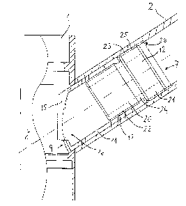
Fig. 1 shows two fitting parts 1 and 2 which may be,
3o for example, a housing, a tubular piece, a hydraulic
appliance, etc., in particular said figure illustrating
preferably a wide fitting part 1 in the form of a
housing part of a water fitting, with an at least
approximately cylindrical outer contour, and a lateral
fitting part 2 in the form of an outflow pipe, with an
outflow 3 for water or another liquid. The term
"hydraulic" refers, within the meaning of the
A13838CA/St/Gb/04.01.2005
' .~ ~ . CA 02361365 2005-O1-13
- 3 -
invention, to any liquid. The outflow pipe 2 has an
axial cavity or passage 4 which communicates with an
orifice forming the outflow 3. The fitting parts 1 and
2 have in each case axial symmetry or longitudinal axes
5 and 6 located in one and the same plane and are
connected to one another in close contact by means of a
fastening device 7.
The fitting part 1 has a cylindrical wall 8 which is
1o provided with a continuous orifice 9 for connection to
the fitting part 2.
The cylindrical wall 8, the shape of which is not
otherwise essentially impaired by the connection to the
fitting part 2, is thus in contact with a sectional
plane of the fitting part 2 which, for this purpose, is
designed in a special form of what is known as a
penetration, so that the shape of one end 10 of the
fitting part 2 is matched to the outer surface of the
cylindrical wall 8 of the fitting part 1 according to
an angle W formed by the axes 5 and 6. As a result, the
tubular fitting part 2, which has the smaller diameter,
can be added, flush, to the fitting part 1 at the
predetermined angle W.
The fastening device 7 according to figs. 1 and 2,
comprises two parts, to be precise a fastening part 11
and a threaded tube 12, both of which are relatively
thin-walled. As illustrated in figures 3 to 6, the
fastening part 11 may preferably be of tubular design
with an orifice 13 and a flange orifice 14. The flange
orifice 14 is located in a front zone 16 having a
flange 15. The flange 15 is of cylindrical and/or
curved design such that its rear side mates with the
cylindrical inner side of the wall 8 of the fitting
part 1. A region at the other end of the fastening part
11 has an internal thread 17 between an annular end
A13838CA/St/Gb/04.01.2005
° . CA 02361365 2005-O1-13
- 4 -
face 18 and a shoulder 19.
The threaded tube 12 according to fig. 2 has a portion
20 with a diameter D'1 and a portion 21 with a diameter
D2 which are provided in each case with an external
thread 22 and 23, D2 being somewhat larger than D1.
Between the portions 20 and 21 is located a threadless
intermediate portion 24, by means of which they are
firmly connected. The external thread 22 of the portion
l0 20 has a smaller pitch than the external thread 23 of
the portion 21. As may be seen from fig. 2, the fitting
part 2 has an internal thread 25 with a pitch which
corresponds to that of the external thread 23. The
internal thread 25 extends from an inner shoulder 26 of
the fitting part 2 toward the zone 16 of the latter,
but over a height which is no greater than about double
the height of the portion 21.
The fastening device according to figures 1 to 6
2o functions as follows:
The fastening part 11, preferably pressed, for example
from plastic, and which is also referred to as a
molding, is inserted from inside into the orifice 9 of
the fitting or housing part 1. By virtue of its shape,
the molding 11 then comes to bear fixedly in terms of
rotation against the housing part. The threaded tube 12
is screwed, via its external thread 22 with the smaller
pitch, into the fastening part 11 up to abutment. The
fitting part 2, which is also referred to as an outflow
pipe, is subsequently added over the portion 21 of the
threaded tube 12 in such a way that the end 10 of said
fitting part bears against the housing part 1 in the
correct position with respect to the angle w. The
threaded tube 12 is then rotated from the housing part
1 by means of a flexible shaft, so that its thread 23
provided with the greater pitch comes into engagement
with the internal thread 25 of the outflow pipe 2. The
A13838CA/St/Gb/04.01.2005
' -' ~ . CA 02361365 2005-O1-13
- 5 -
threaded tube 12 being firmly rotated, the outflow pipe
2 is pressed with considerable force against the
housing part 1. Very high forces can be achieved as a
result of the pitch difference. Alternatively, the
thread with the large pitch may also be arranged on the
molding side and that with the smaller pitch on the
outflow-pipe side.
One possible version of the flange 15 of the fastening
to part 11 in the region of the orifice 9 of the fitting
part 1 is illustrated, enlarged, in figures 7 and 8, in
which the duct-like communication 27 between the two
fitting parts 1 and 2 is also indicated.
The version according to figs. 9 and 10 comprises a
fastening part 11 of the same type as, or of a similar
type to the version according to fig. 2. However,
according to this version, the threaded tube 28 has a
lower portion 29 with an external thread 30 and a
2o smooth upper portion 31 which terminates in an annular
projecting flange 32. In this case, the fitting part is
designed in the form of an outflow pipe piece 33 and
has an axial cavity or passage 4 with a mouth 34. In
this case, too, the fitting parts 1 and 33 have in each
case axial longitudinal axes 5 and 6, which are located
in one and the same plane, and are connected to one
another in close contact by means of the fastening
device 7. The outflow pipe piece 33 is held clamped as
a result of the action of the external thread 30,
co-operating with the internal thread on the fastening
part 11, of the threaded tube 28 and of its shoulder 32
which presses agains an annular step 35 of the outflow
pipe piece 33 as a countershoulder.
The fastening device according to figs. 9 and 10
functions as follows:
The preferably pressed fastening part 11, which is also
A13838CA/St/Gb/04.01.2005
_' ~ °~ ~ . CA 02361365 2005-O1-13
- 6 -
referred to as a molding, is inserted from inside into
the orifice 9 of the fitting or housing part 1. By
virtue of its shape, the molding 11 then comes to bear
fixedly in terms of rotation against the housing part 1
at the angle W. The threaded tube 28 is introduced
through the orifice 34 of the outflow pipe piece 33 up
to abutment at the step 35. The outflow pipe piece 33
is thereafter added over the fastening part 11 in such
a way that the latter comes to bear on the housing part
1 in the correct rotary position with respect to the
angle W. The threaded tube 28 is then rotated from the
housing part 1 or preferably from the side facing away
from the housing part 1 by means of an, if appropriate,
flexible shaft, until the outflow pipe piece 33 presses
against the housing part 1. The threaded tube 28 thus,
on the one hand, comes into engagement with the
internal thread 17 of the fastening part 11 and, on the
other hand, presses with the shoulder 32 against the
step 35 of the outflow pipe piece 33. The selected
dimensions are such that, in this position, the end
region of the fitting part 33 is in contact with the
outer surface 8 of the fitting part 1. A further
tubular element 36 can subsequently be inserted into
the outflow pipe piece 33 and be fastened by means of a
snap fastening 37.
In the examples described, the fastening device 11, 12
or 11, 28 is intended to be installed in a lateral
fitting part 2, 33 which, in one end region, has a
cavity 4 in which there is, preferably peripherally, an
inner fastening means 25 and 35 for the fastening
device 7. However, other fastening means could also be
used.
By means of the fastening device according to the
invention, the connection between the fitting parts 1
and 2 or 1 and 33 is not readily releasable, so that a
A13838CA/St/Gb/04.01.2005
CA 02361365 2005-O1-13
complete unit, as a replacement for a corresponding
one-piece structure, is thereby obtained. The two
unreleasably connected parts prove particularly
advantageous in terms of their surface treatment. This
is because a corresponding one-piece structure would be
relatively difficult to clean, grind, polish,
chromium-plate, lacquer, etc., particularly in the
region of the sharp-edged contact line of the two
fitting parts. Since, according to the invention, the
fitting parts 1, 2 or the outflow pipe 33 are
originally separate, such surface treatments can be
carried out satisfactorily.
It is unimportant for the present invention whether the
cross sections of the fitted parts 1 and 2 are circular
or have another, for example elliptic shape. The
cylindrical wall 8 is therefore to be understood, in
general, as the outer wall of the fitting part 1.
2o In all these variants, the passage or the orifice
through all the elements may be such that a flexible or
more or less rigid small tube serving as a water
conduit can be led not only through the cavities of the
housing part 1 and of the outflow pipe 2 or 33, but
also through the fastening device 7. In particular, a
flexible hose of a pull-out shower can be led through.
A13838CA/St/Gb/04.01.2005