Language selection

Search

Patent 2361400 Summary

Third-party information liability

Some of the information on this Web page has been provided by external sources. The Government of Canada is not responsible for the accuracy, reliability or currency of the information supplied by external sources. Users wishing to rely upon this information should consult directly with the source of the information. Content provided by external sources is not subject to official languages, privacy and accessibility requirements.

Claims and Abstract availability

Any discrepancies in the text and image of the Claims and Abstract are due to differing posting times. Text of the Claims and Abstract are posted:

  • At the time the application is open to public inspection;
  • At the time of issue of the patent (grant).
(12) Patent Application: (11) CA 2361400
(54) English Title: DEVICE AND METHOD FOR MEASURING PARALLELISM AND ALIGNMENT OF ROLLS
(54) French Title: DISPOSITIF ET PROCEDE POUR MESURER LE PARALLELISME ET L'ALIGNEMENT DE CYLINDRES
Status: Deemed Abandoned and Beyond the Period of Reinstatement - Pending Response to Notice of Disregarded Communication
Bibliographic Data
(51) International Patent Classification (IPC):
  • G1B 11/27 (2006.01)
  • G1B 21/24 (2006.01)
(72) Inventors :
  • ALBRECHT, CHRISTIAN (Germany)
  • HERMANN, MICHAEL (Germany)
(73) Owners :
  • PRUFTECHNIK DIETER BUSCH AG
(71) Applicants :
  • PRUFTECHNIK DIETER BUSCH AG (Germany)
(74) Agent: KIRBY EADES GALE BAKER
(74) Associate agent:
(45) Issued:
(86) PCT Filing Date: 2000-12-08
(87) Open to Public Inspection: 2001-06-14
Examination requested: 2005-08-22
Availability of licence: N/A
Dedicated to the Public: N/A
(25) Language of filing: English

Patent Cooperation Treaty (PCT): Yes
(86) PCT Filing Number: PCT/DE2000/004375
(87) International Publication Number: DE2000004375
(85) National Entry: 2001-07-31

(30) Application Priority Data:
Application No. Country/Territory Date
199 59 866.5 (Germany) 1999-12-10

Abstracts

English Abstract


The invention relates to a measuring device and optionally to a corresponding
adapter that facilitate a quantitative measurement of parallelism and
alignment of rolls. Said measuring device is mounted on the front ends of said
rolls. A specific embodiment relates to a projection device for emitting a
light beam or a fan of light. The light beams emitted by said projection
device are incident on a high-precision reception device. The reception device
is also mounted on a front end of the roll.


French Abstract

L'invention concerne un appareil de mesure et éventuellement un adaptateur associé permettant la détermination quantitative du parallélisme et de l'alignement de cylindres, cet appareil étant placé sur une extrémité de ces derniers. Selon un mode de réalisation de la présente invention, un appareil de projection est prévu, qui envoie un rayon ou un éventail lumineux. Les rayons lumineux émis par celui-ci rencontrent un appareil de réception de haute précision, également placé sur une extrémité d'un cylindre.

Claims

Note: Claims are shown in the official language in which they were submitted.

5
Claims
1. Device for checking or measuring the parallel position and/or the axially
aligned
offset of two rollers or other cylindrical bodies, characterized in that one
shaft end (12) of a
roller (10) has an end face (14) which has been machined with high precision
and to which
either a measurement device (18) equipped with a highly plane surface for
determining the
angular orientation can be attached directly or using an adapter (20) which
has been worked
with high precision.
2. Device as claimed in claim 2, wherein the measurement device (18) is
provided
with a prismatic notch (30) which has been produced with high precision and
which can be
placed on the cylinder jacket surface of an adapter (20).
3. Device as claimed in claim 2 or 3, wherein the measurement device (18) has
orientation sensors which operate with high precision in the form of laser
gyros.
4. Device as claimed in claim 1, wherein there is a first measurement device
(60)
which is suitable for receiving light beams of a narrow cross section and
receiving several
light beams which span a plane, and wherein there is a second measurement
device which can
emit a light beam of narrow cross section or a light band of low thickness
exactly
perpendicularly to the axis of a roller so that a sensor which is present in
the measurement
device (60) can be centrally hit when the rollers (10, 70) are optimally
aligned.

Description

Note: Descriptions are shown in the official language in which they were submitted.


30-Jug-Ol 17:17 5.03
'730370 N 1 XUN YtNtlIJIJY LL.Y .~ 1~ trot ~ uG. ~ ~o i rro . ~o
X
Prueftechr~iJc. Dieter Busch AO
D 85737 Ism,aning
patent Applfeation
Title
Device and pcoeess for measuring the parallalisrn
and sligned position of rollers
Prior Art
A device for measuring the parallelism of rollers or other bodies based on
high-
precision optical gyroscopes or Gyroscopes which operate with high precision
with
micromechanieally pmdueed oecillatota is 1csiown. Reference is made to the
applications of
the company Prueftvchnik Ao, D 85737, Iamaning.
object
The object to be achieved is to devise a device and the pertinent process ao
that the
parallelism of rollers cars be measured more easily. Another object is to
dcviso at the same
time a dcviao and an arrangement such that the aligned position (i.e. the
offset in the axial
direction) of rollers can be determined comfortably, easily and economically.
Approach
these objects are achieved by a device and its uoe, and a process for
producing one
such device, which make it possible for s measureanent device for dotannining
the angular
orientation of a body to be attached directly to the and face or a cylinder
cover surface. In
another embodiment of the invention, these objects are achieved by a device,
which acts as an
adapter, in which likawis8 a measurement device for detemnining the angular
orientation of a
body can be attached to the end face. In still another embodiment of the inv
c~ntion these
objects are achieved by a projection device for Handing a light beam or a
light fan which
intarworks with a receiving device, which allows an accurate impact site of
one such light
beam or light fan to be determined in a very precise manner.
CA 02361400 2001-07-31

30-Jul-Ol 17:17 5.04
7~88303?6 NIXUN YtHIiUlJY LLI' J14 1"YJJ Jt.x.. .mut rro.ca
Z
Embodiments:
The invention is described below using the draw'snga.
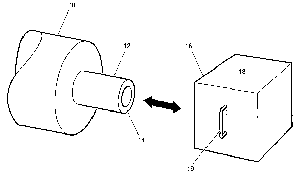
Figure 1 shows a perspeotivo view of a first embodimtnt of the invention
Figure 2 shows a perspective of a second embodiment of the invention which
contains
an intermediste piece which acts as an adapfer
Figure 3 shows another embodiment of the invention, similar to Figure 2, with
a
measurement device which has been made differently
Figure 4 shows a aide view as shown in Figures 2 sad 3, partially in a cross
section
Figure 5 shows a side view similar to Figure 4
Figure 6 shows a perspective view of a measurement menu for measuring or
checking the aligned position of two rollers
Figure 7 shows a screen for displaying and indicating a possible alignment
error
between iwo rollers.
Figure 1 as au essential element of the invention has a surface (end face) 14
which ha:
bean maehiaed with high precision, i.e. the surface of en axle 12 which is
used to support a
collar l0, which has been produced with high precision, as is used for example
in the printing
industry or for producing paper, films or sheet metal. The surflaCe 16 of an
orientation
measurement device 18, a surface which has been machined vuith high precision,
can be
placed against a surface 14 which has bean likewise been machined with high
praciaion. This
device preferably contains ono or more so-called laser gyros and is able to
determine its
orientation in apace with extremely high precision. It aaa be moved by meams
of holding and
transport handles into its measurement position at which by pressing a button
or with
suffciently high contact pressure of the devise on the surface ld a
measurement is taken, or
the start of several successive measurcrncnts is initiated. Advantageously,
the measurement
device 18 has a permanent magilet which makes it possible for the device to be
placed against
the ferrornagnetica working surface 14 and to make contact with it in a very
reproducible
manner.
CA 02361400 2001-07-31

30-Ju'1 -Ol 17 : 17 5. 06
?0388303~ffd N 1XUN h'~JUUY LLh' :i14 P04 JL~ 30 ' 01 ~: 26
3
Figure 2 shawg one altornative in which an adapter 20 which has been produced
with
high preeieion and, which, thus, represents an extension of the axle is used.
tts cylinder
surface has been machined with high precision, in the same way as are cover
susfaces 24 and
42 (Figure 4). The adapter 20 is preferably produced from tempered aluminum,
chromium
nickel steel or a titanium alloy, or from a ceramic tnaterlal, especially one
with sn
approximately dissppoaring coefficient of thermal expansion. The adapter makes
it possible
to place the mossurement device 18 also against those shaft ends which cannot
otherwise
snake contact with a frame or the like in the desired plane-parallel manner.
For defined
temporary attachment of the adapter 20 there is a threaded stub 22 which cen
be screwed into
and out of a threaded hole 15.
Figure 3 shows how a measurement device 18 which has a prismatic notch on its
bottom (reference number 30) can be placed on the cylinder jacket of the
adapter 20 in a high
precision manner.
Figure 4 shows further details of one structurally pteferrcd embodiment of the
shaft
12 and the adapter 20. No special demands are imposed on the threaded hole 15.
To protect
the high precision and face I4 there is a protective cap 40 which is
temporarily removed for
purposes of acquiring the measured value, compere also Figure 5. Instead of a
plane, high
precision surface 42, there can optionally also be a conical surface, as shown
by seferenee
aumbar 44.
Figure 6 shows how the measurement device for raeasuring the aligned position
of
two rollers works. The measurement instruments 60, 62 can contain gyroscopes,
but need not
necessarily do so. Hut there is a device which omits exactly at a right angle
to the axis of the
roller 10 or the adapter 20 for atnitting a light beam or essrsitially a fist
light the, thexefare,
light beams which forth a plane. To do this, the messuremvnt jrrsts 6z which
acts as
the emitter advantageously has an illumination device which is designed either
as a laatr or
has another light source which illuminates a slot which is roughly 10 to 200 m
icrons wide.
This slot is projected with a projection objective lens with a focal length of
mug151y 0.5 to 30
CA 02361400 2001-07-31

30-Jug-Ol 17:18 5.06
'11~3H~.5'lld N1XUN YtH~'f LLh' 314 1'(as JL~.. ~ '01 08:29
4
m onto the receiving davioe 60. The latter contains a photosensitive element,
especially a
high precision CMOS pixel sensor array which works with high resolution. Its
pixels hsve a
distance of typically: 10 microns or less so that especially using an
averaging acquisition and
cornputatioa pmceas the center of the incident light beam can be determined
very aoourately.
At the same time the locstion of the received light beam on the detector can
be displayed
easily by means of a commercial portable computer which also computes the
location of the
center. For this purpose the components HDCS 1000 or HDCS 2000 from Hewlett
Packard
are especially well suited, but also other photosensitive electronic
components are suitable for
the indicated center determination. As shown in Figure 6, the measurement
devices b0, 62
fvr parrying out a measurement pmces: are placed on the end faces 24 (or 14)
(see arrows P t
and P2). In this way a high precision measurement possibility is created with
extitmely
etonomical means, with which possible alignment errors can be checked or
determined in a
very short tithe. In addition, the measurement daviae pan be oheaked for
correct operation
using simple means, !br example using a granite table. It is preferred the
measurement device
60 be connected to a pertinent computer (poetabfe computer) by means of a so-
called USH
interface.
Figure 7 shows a projection image of the indicated slot obtained in this way;
it has
been projected directly onto the photosensitive elements of a two-
dimensionally operating
CM09 pixel eansor. The minimum light intensity betwaon the two central
projection strips
can be easily determined to a precision of 0.1. The accuracy can bt
eigni~cantly increased by
algorithms for determining the average value.
CA 02361400 2001-07-31

Representative Drawing
A single figure which represents the drawing illustrating the invention.
Administrative Status

2024-08-01:As part of the Next Generation Patents (NGP) transition, the Canadian Patents Database (CPD) now contains a more detailed Event History, which replicates the Event Log of our new back-office solution.

Please note that "Inactive:" events refers to events no longer in use in our new back-office solution.

For a clearer understanding of the status of the application/patent presented on this page, the site Disclaimer , as well as the definitions for Patent , Event History , Maintenance Fee  and Payment History  should be consulted.

Event History

Description Date
Application Not Reinstated by Deadline 2008-07-31
Inactive: Dead - No reply to s.30(2) Rules requisition 2008-07-31
Deemed Abandoned - Failure to Respond to Maintenance Fee Notice 2007-12-10
Inactive: Abandoned - No reply to s.30(2) Rules requisition 2007-07-31
Inactive: S.30(2) Rules - Examiner requisition 2007-01-31
Letter Sent 2005-09-12
Request for Examination Received 2005-08-22
All Requirements for Examination Determined Compliant 2005-08-22
Request for Examination Requirements Determined Compliant 2005-08-22
Letter Sent 2002-04-25
Inactive: Single transfer 2002-03-15
Inactive: Cover page published 2001-12-13
Inactive: Courtesy letter - Evidence 2001-12-11
Inactive: First IPC assigned 2001-12-04
Inactive: Notice - National entry - No RFE 2001-12-04
Application Received - PCT 2001-11-22
Application Published (Open to Public Inspection) 2001-06-14

Abandonment History

Abandonment Date Reason Reinstatement Date
2007-12-10

Maintenance Fee

The last payment was received on 2006-11-27

Note : If the full payment has not been received on or before the date indicated, a further fee may be required which may be one of the following

  • the reinstatement fee;
  • the late payment fee; or
  • additional fee to reverse deemed expiry.

Patent fees are adjusted on the 1st of January every year. The amounts above are the current amounts if received by December 31 of the current year.
Please refer to the CIPO Patent Fees web page to see all current fee amounts.

Fee History

Fee Type Anniversary Year Due Date Paid Date
Basic national fee - standard 2001-07-31
Registration of a document 2001-07-31
MF (application, 2nd anniv.) - standard 02 2002-12-09 2002-09-16
MF (application, 3rd anniv.) - standard 03 2003-12-08 2003-09-19
MF (application, 4th anniv.) - standard 04 2004-12-08 2004-11-25
Request for examination - standard 2005-08-22
MF (application, 5th anniv.) - standard 05 2005-12-08 2005-11-24
MF (application, 6th anniv.) - standard 06 2006-12-08 2006-11-27
Owners on Record

Note: Records showing the ownership history in alphabetical order.

Current Owners on Record
PRUFTECHNIK DIETER BUSCH AG
Past Owners on Record
CHRISTIAN ALBRECHT
MICHAEL HERMANN
Past Owners that do not appear in the "Owners on Record" listing will appear in other documentation within the application.
Documents

To view selected files, please enter reCAPTCHA code :


To view images, click a link in the Document Description column (Temporarily unavailable). To download the documents, select one or more checkboxes in the first column and then click the "Download Selected in PDF format (Zip Archive)" or the "Download Selected as Single PDF" button.

List of published and non-published patent-specific documents on the CPD .

If you have any difficulty accessing content, you can call the Client Service Centre at 1-866-997-1936 or send them an e-mail at CIPO Client Service Centre.

({010=All Documents, 020=As Filed, 030=As Open to Public Inspection, 040=At Issuance, 050=Examination, 060=Incoming Correspondence, 070=Miscellaneous, 080=Outgoing Correspondence, 090=Payment})


Document
Description 
Date
(yyyy-mm-dd) 
Number of pages   Size of Image (KB) 
Representative drawing 2001-07-30 1 7
Abstract 2001-07-30 1 15
Description 2001-07-30 4 182
Drawings 2001-07-30 7 102
Claims 2001-07-30 1 33
Notice of National Entry 2001-12-03 1 195
Courtesy - Certificate of registration (related document(s)) 2002-04-24 1 114
Reminder of maintenance fee due 2002-08-11 1 114
Reminder - Request for Examination 2005-08-08 1 115
Acknowledgement of Request for Examination 2005-09-11 1 177
Courtesy - Abandonment Letter (Maintenance Fee) 2008-02-03 1 176
Courtesy - Abandonment Letter (R30(2)) 2007-10-22 1 165
PCT 2001-07-30 8 256
Correspondence 2001-12-03 1 24