Note: Descriptions are shown in the official language in which they were submitted.
CA 02362083 2002-O1-07
2
DESCRIPTION
TECHNICAL FIELD AND BACKGROUND OF INVENTION
S
This invention relates to a handle attachment for
scissors,'such as conventional splicer snips used for
cutting wire and cable. The invention is a retrofit item
adapted to fit onto the existing handle portion of
scissors to facilitate gripping, increase comfort, and
reduce the incidence of injury to the user resulting from
repeated use.
In recent years, the "human engineering" of useful tools
and articles prevalent in the workplace has demanded
increased consideration. "Ergonomics", as its called, is
an applied science concerned with certain human
characteristics that need to be considered when designing
and arranging things that we use in order that people and
things will interact most effectively and safely. The
impact of ergonomics takes years to develop and as such,
cannot be studied in brief. Tools and articles which are
designed without ergonomic consideration may result in
eventual injury to the user.
CA 02362083 2002-O1-07
These injuries are referred to generally as cumulative
trauma disorders, repetitive motion injuries, or
repetitive stress injuries; terms which will be used
interchangeably herein. The injury is caused by a motion
or impact where the contact may be small and by itself
would do no real damage, but after hundreds or thousands
of repetitions affecting the same area of the body over a
period of time, the cumulative damage created can be
immense. One of the most commonly known cumulative trauma
disorder is carpal tunnel syndrome.
Carpal tunnel syndrome i.s a condition impacting the hand
and wrist which has been linked to occupations that
require repetitive use of the hands, such as typing. The
condition generally results when the median nerve fails
to work properly. This is thought to occur because of too
much pressure on the nerve as it runs into the wrist
through an opening called the "carpal tunnel".
This occurrence is best understood given a brief
explanation of some of the anatomy of the wrist. The
median nerve runs into the hand to supply sensation to
the thumb, index finger, long finger, and half of the
CA 02362083 2002-O1-07
4
ring finger. The nerve also supplies a branch to the
muscles of the thumb, the thenar muscles. These muscles
help move the thumb and are very important in moving the
thumb so that it can touch each of the other fingers.
This motion is called opposition.
The carpal tunnel is an opening into the hand that is
made up of the bones of the wrist on the bottom and the
transverse carpal ligament on the top. Through this
opening, the median nerve and the flexor tendons run into
the hand. The median nerve lies just under the transverse
carpal ligament.
The flexor tendons are important because they allow us to
move the fingers and the hand, such as when we grasp
objects. The tendons are covered by a material called
tensynovium. The tensynovium is very slippery, and allows
the tendons to glide against each other as the hand is
used to grasp objects. Any condition that causes
irritation or inflammation of the tendons can result in
swelling and thickening of the tensynovium. As the
tensynovium covering all the tendons begins to swell and
thicken, pressure begins to increase in the carpel tunnel
because the bones and ligaments that make up the tunnel
CA 02362083 2002-O1-07
are not able to stretch in response to the swelling.
Increased pressure in the carpal tunnel begins to squeeze
the median nerve against the transverse carpal ligament
because the nerve is the softest structure in the carpal
5 tunnel. Eventually, the pressure reaches a point when the
nerve can no longer function normally. This results in
pain and numbness in the hand.
One of the first symptoms of carpal tunnel syndrome is
numbness in the distribution of the median nerve. This is
quickly followed by pain in the same distribution. The
pain may also radiate up the arm to the shoulder and
sometimes the neck. If the condition is allowed to
progress, weakness the thenar muscles can occur. This
results in an inability to bring the thumb into
opposition with the other fingers, thereby hindering a
persons ability to grasp.
Recently, physicians have begun to recognize that
activities that involve highly repetitive use of the
hands can result in carpal tunnel syndrome, especially if
the wrist is bent. When the wrist is bent away from a
neutral position (straight), the tendons and tensynovium
are drawn across the bones of the wrist or transverse
CA 02362083 2002-O1-07
6
carpal ligament at an angle. This increases the normal
pressure and friction that the tensynovium is designed to
prevent. Over an extended time, this internal strain is
thought to contribute greatly to the development of
carpal tunnel syndrome. Additional factors that are
thought to contribute to carpal tunnel syndrome are
rheumatoid arthritis, previous injuries to the hand or
wrist (especially broken bones), a cyst on the tendon,
diabetes, and an underactive Thyroid.
Additionally, physicians have been concerned about the
effects of repeated high stress loading of the palm. This
occurs during routine tasks such as using pliers.
Repetitive high stress grasping like this is thought to
injure the tendons and tensynovium of the hand.
Shands' Handbook of Orthopedic Surgery provides the
following description of the anatomy of the soft tissue
of the wrist and hand:
"Where long flexor tendons must pull at an angle, as in
the wrist, distal palm (close to the fingers), and
digits, they are invested (surrounded) in a double-
layered synovial sac or tendon sheath (tensynovium). This
CA 02362083 2002-O1-07
7
delicate membrane facilitates the smooth gliding of the
tendon. To prevent the flexor tendons from bow-stringing
in the distal palm and fingers, the tendons and their
synovial sheaths are incased in ligamentous tunnels. In
these narrow passages, fibrous adhesions (bumps) of the
tendon, sheath, and tunnel wall may immobilize the tendon
and destroy it's function."
With the tendons responsible for the flexing of the
fingers running through the palm in these ligamentous
tunnels, it follows how the tensynovium in them becomes
irritated by repeated applications of high pressure or a
sudden impact. There is little protection for these
tendons and tunnel. Sudden impacts to the palm, like
those generated when using the palm as a hammer to, for
example, drive a screwdriver in to wedge a splice case
open, can cause the tunnels to swell and pinch against
the tendon. Continued use of the hand exacerbates the
swelling. The next event will generally cause significant
pain and associated dysfunction in the fingers as well as
the wrist.
In view of the above considerations, it became apparent
to the Applicant that scissors used by splicers, called
CA 02362083 2002-O1-07
"snips", needed to be evaluated with respect to carpal
tunnel syndrome and other repetitive motion injuries. The
dangers of being cut by a sharp snip are apparent, but
what about the wear and tear on the palm of the hand
after splicing 2500 or 3000 pair cable.
With the typical snip, a relatively small thumb ring is
placed against the mid-portion of the palm while the
middle or ring finger is used to open and close the snip.
This small thumb ring, which has an effective pressure
area of less than 1/4 square inch, is repeatedly forced
into the palm with each cut. On difficult cuts, the thumb
ring has a tendency to slide up the palm into the distal
region. To maintain control of the snip and complete the
cut, the wrist must be rotated out of the neutral
position. This opens the door to carpal tunnel syndrome
resulting from cumulative stress.
Moreover, the thumb ring typically rests directly over
the tendon and tunnel of the finger responsible for the
opposing force to make the cuts. In this case, any
swelling in the tensynovium is compressed by the thumb
ring thereby magnifying the resulting pressure on the
tendon.
CA 02362083 2002-O1-07
9
To combat this problem, the Applicant sought to develop a
device that would provide an effective reduction of the
stresses contributing to this and other cumulative trauma
disorders. A program was launched with three main goals
in mind:
1. Design a device to effectively reduce the stress and
strain placed on the palm (and resultant tendons and
tunnels).
2. Design a device to provide increased stability in
the hand thus eliminating the need for bending of the
wrist.
3. Design a device so that it could be retrofitted to
any brand of snip, thus making it accessible to all
users.
The primary objective was to reduce the pressure on the
tendons and tunnels. This is accomplished in the present
invention by increasing the area of contact in the palm.
By creating a handle attachment that both widens and
lengthens the contact of the snip in the palm as well as
CA 02362083 2002-O1-07
contouring the attachment to fit the arch of the palm,
this goal was achieved. Additionally, Applicant
determined that by lengthening the handle of the snip
through the present attachment, the little finger could
5 be employed to stabilize the snip in the hand, thus
eliminating the need to bend the wrist during cutting.
Accommodation for the little finger was made by slightly
raising the lengthened portion of the handle attachment.
10 The first prototypes of the invention achieved the
targeted objectives and more. The pressure area was
increased to over 11/4 square inches. This results in
more than an 80% decrease in the pressure on the palm.
The new stability enabled the user to make repeated cuts
without fear of the snip shifting in their palm. The
amount of effort to make the cut was also reduced, thus
producing less fatigue.
Dean Chappell, OHST Safely Director-Eastern zone GTE
Service Corporation, states it clearly: "The hand can
create more force when using a full handgrip. A pinch
grip should only be used for precision work or when
handling small objects." To satisfy the occasional need
for a pinch grip. Applicant formed the invention with a
CA 02362083 2002-O1-07
11
thumb ring opening. As a final design step, the invention
was injection molded with a textured outer surface to
further enhance its grip, even in the most adverse
conditions, and was made in a bright red color to make
the snip/handle attachment easier to locate if dropped.
SUMMARY OF THE INVENTION
Therefore, it is an object of the invention to provide a
handle attachment for scissors which reduces the
incidence of repetitive motion or stress injuries,
cumulative trauma disorders, and on-the-job fatigue.
It is another object of the invention to provide a handle
attachment which increases the stability of the scissors
within the hand thus eliminating the need to bend the
wrist when making a cut.
It is another object of the invention to provide a handle
attachment which is capable of being retrofitted to most
brands of splicer snips.
It is another object of the invention to provide a handle
attachment which is contoured to fit comfortably within
CA 02362083 2002-O1-07
12
the palm of the user.
It is another object of the invention to provide a handle
attachment which is injection molded from a lightweight
polymer.
It is another object of the invention to provide a handle
attachment which is relatively inexpensive to
manufacture.
These and other objects of the present invention are
achieved in the preferred embodiments disclosed below by
providing a retrofit handle attachment for scissors. The
attachment includes a contoured attachment body adapted
for being secured to a handle portion of the scissors and
held in a palm of a user. The attachment body defines an
enlarged surface area for being gripped by the user.
Means are provided for securing the attachment body to
the handle portion of the scissors, whereby the handle
attachment increases the comfort of the scissors in the
palm of the user to reduce fatigue and the incidence of
repetitive motion injury.
According to another preferred embodiment of the
CA 02362083 2002-O1-07
13
invention, the attachment body includes first and second
overlying halves having respective inside and outside
major surfaces. The inside major surfaces define a space
between each other adapted for accommodating the handle
portion of the scissors.
According to yet another preferred embodiment of the
invention, the outside major surfaces of the first and
second halves are textured to increase the grip of the
attachment.
According to yet another preferred embodiment of the
invention, the attachment body includes a finger ring
opening adapted for being aligned with a finger ring
opening of the scissors.
According to yet another preferred embodiment of the
invention, the attachment body includes a contoured palm-
engaging extension shaped for being engaged by the little
finger of the user.
According to yet another preferred embodiment of the
invention, the attachment body includes a relatively
wide, palm-engaging perimeter wall having a dimension of
CA 02362083 2002-O1-07
14
between 0.2 and 0.5 inches.
According to yet another preferred embodiment of the
invention, the attachment body is formed of a molded
polymer.
According to yet another preferred embodiment of the
invention, the attachment body is formed of metal.
In another embodiment, a retrofit handle attachment for
scissors a contoured attachment body formed of a polymer
and adapted for being secured to a handle portion of the
scissors and held in a palm of a user. The attachment
body defines an enlarged surface area for being gripped
by the user and includes first and second overlying
halves having respective inside and outside major
surfaces. The inside major surfaces define a space
between each other adapted for accommodating the handle
portion of the scissors. Means are provided for securing
the attachment body to the handle portion of the
scissors, whereby the handle attachment increases the
comfort of the scissors in the palm of the user to reduce
fatigue and the incidence of repetitive motion injury.
CA 02362083 2002-O1-07
According to another preferred embodiment of the
invention, the first and second halves of the attachment
body are connected together by means of one or more
removable fasteners.
5
According to yet another preferred embodiment of the
invention, the fasteners are externally-threaded screws.
BRIEF DESCRIPTION OF THE DRAWINGS
Some of the objects of the invention have been set forth
above. Other objects and advantages of the invention will
appear as the description proceeds when taken in
conjunction with the following drawings, in which:
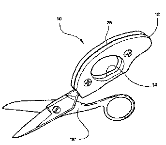
FIG. 1 is a perspective view of the retrofit handle
attachment in an assembled condition on the handle
portion of the scissors;
FIG. 2 is an exploded view of the retrofit handle
attachment with its halves separated and spaced apart
from the scissors;
FIG. 3 is a plan view showing an inside major surface of
CA 02362083 2002-O1-07
16
one of the attachment halves; and
FIG. 4 is a perspective view of the scissors and handle
attachment positioned within the palm of a user.
DESCRIPTION OF THE PREFERRED EMBODIMENT AND BEST MODE
Referring now specifically to the drawings, a retrofit
handle attachment according to the present invention is
illustrated in FIG. 1 and shown generally at reference
numeral 10. The handle attachment 10 is especially
applicable for use with scissors "S" used by splicers to
cut wire and cable. The attachment 10 may have further
application to other hand-held tools and implements, such
as pliers.
Referring to FIGS. 2 and 3, the handle attachment 10 is
formed of an attachment body 12 contoured to fit
comfortably within the hand of the user. The attachment
body 12 includes first and second opposing halves 12A and
12B which fit together on either side of a finger ring
"R" formed with the handle portion of the scissors "S".
The halves 12A and 12B are preferably formed of an
injection molded polymer, such as ABS, or metal. Each
CA 02362083 2002-O1-07
17
half 12A, 12B has a center opening 14 and a recessed
shoulder 15 formed with its inside major surface and
extending around the perimeter of the center opening 14
for receiving the finger ring "R" of the scissors "S". A
further recess 18 extends outwardly from the recessed
shoulder 15 to an end of the half 12A, and cooperates
with an identical recess formed with the opposing half
12B to form a bed for receiving the shank "H" of the
scissors. Cavities 21 and 22 are preferably formed with
each half 12A and 12B to reduce the overall weight and
manufacturing cost of the handle attachment 10.
According to one embodiment, a perimeter lip 24 is formed
around the half 12A and mates with a corresponding groove
(not shown) formed around the perimeter of the half 12B
upon assembly of the handle attachment 10 on the scissors
"S". Once assembled, the halves 12A and 12B of the
attachment body 12 cooperate to form a relatively wide
perimeter wall 25 (See FIG. 1) a dimension of between 0.3
and 0.6 inches, and defining an enlarged surface area for
engaging the palm of the user when making a cut. The wide
perimeter wall 25 increases the pressure area on the
palm, thereby providing increased comfort to the user and
reducing the incidence of repetitive motion injury.
CA 02362083 2002-O1-07
18
Threaded screws 26 and 27 are inserted through
complementary-threaded openings 31, 32, 33, and 34 formed
in the halves 12A, 12B to secure the handle attachment 10
to the scissors "S". The halves 12A, 12B may
alternatively be attached using any suitable adhesive or,
in the case of metal halves, by welding. With the
exception of the perimeter lip and groove, the halves 12A
and 12B are preferably identical. In another embodiment
(not shown), the attachment body includes only one of the
halves, and a holding plate for securing the handle
attachment to the scissors.
As best shown in FIG. 4, the attachment body 12
preferably has a contoured palm-engaging extension 35
which is shaped for being engaged by the little finger of
the user when holding and using the scissors "S". This
area 35 facilitates proper gripping and provides
increased comfort to the hand. In addition, the outside
major surfaces of the halves 12A, 12B may have an
integrally molded rough texture to further promote
gripping.
A retrofit handle attachment for scissors is described
CA 02362083 2002-O1-07
19
above. Various details of the invention may be changed
without departing from its scope. Furthermore, the
foregoing description of the preferred embodiment of the
invention and the best mode for practicing the invention
are provided for the purpose of illustration only and not
for the purpose of limitation--the invention being
defined by the claims.