Language selection

Search

Patent 2362713 Summary

Third-party information liability

Some of the information on this Web page has been provided by external sources. The Government of Canada is not responsible for the accuracy, reliability or currency of the information supplied by external sources. Users wishing to rely upon this information should consult directly with the source of the information. Content provided by external sources is not subject to official languages, privacy and accessibility requirements.

Claims and Abstract availability

Any discrepancies in the text and image of the Claims and Abstract are due to differing posting times. Text of the Claims and Abstract are posted:

  • At the time the application is open to public inspection;
  • At the time of issue of the patent (grant).
(12) Patent: (11) CA 2362713
(54) English Title: METHOD AND DEVICE FOR WELDING SHEETS
(54) French Title: PROCEDE ET DISPOSITIF POUR SOUDER DES TOLES
Status: Expired and beyond the Period of Reversal
Bibliographic Data
(51) International Patent Classification (IPC):
  • B23K 31/12 (2006.01)
  • B23K 15/00 (2006.01)
  • B23K 37/04 (2006.01)
(72) Inventors :
  • BUCHER, ROMEO (Switzerland)
  • KAEGI, BRUNO (Switzerland)
(73) Owners :
  • ELPATRONIC AG
(71) Applicants :
  • ELPATRONIC AG (Switzerland)
(74) Agent: ROBIC AGENCE PI S.E.C./ROBIC IP AGENCY LP
(74) Associate agent:
(45) Issued: 2007-11-13
(86) PCT Filing Date: 2000-02-15
(87) Open to Public Inspection: 2000-09-14
Examination requested: 2004-12-16
Availability of licence: N/A
Dedicated to the Public: N/A
(25) Language of filing: English

Patent Cooperation Treaty (PCT): Yes
(86) PCT Filing Number: PCT/CH2000/000086
(87) International Publication Number: WO 2000053366
(85) National Entry: 2001-08-16

(30) Application Priority Data:
Application No. Country/Territory Date
423/99 (Switzerland) 1999-03-08

Abstracts

English Abstract


During the welding of tailored blanks, the edges (2', 3') of the sheets (2, 3)
are detected in the welding device (1) by sensing elements
(6, 7). One of the edges is designated a reference edge and the other is
adapted to this reference edge using a machining device (10). The
sheets are then aligned with their edges and welded using a laser beam (5).
This provides a simple means of obtaining an allowable gap
value for the welding.


French Abstract

Lors du soudage d'ébauches sur mesure, les arêtes (2', 3') des tôles (2, 3) dans le dispositif de soudage (1) sont détectées par des palpeurs (6, 7). Une des arêtes est déterminée en tant qu'arête de référence et les autres arêtes sont adaptées à l'arête de référence par l'intermédiaire d'une unité d'usinage (10). Les tôles sont ensuite réunies au niveau de leurs arêtes et soudées au moyen d'un rayon laser (5). Il est ainsi facile d'obtenir une valeur d'espacement admissible pour le soudage.

Claims

Note: Claims are shown in the official language in which they were submitted.

6
Claims
1. Method for welding metal sheets (2, 3) to form tailored blanks,
characterized in that the
edge line of both sheets is detected in the welding machine, the edge line of
one of the
sheets is identified as the dominant edge line and the other edge (2', 3') is
reworked to
match it to the dominant edge, and in that the sheets are then welded.
2. Apparatus according to Claim 1, characterized in that a sheet is discarded
before
reworking takes place, if the deviation of its edge from the dominant edge
exceeds a
predetermined amount.
3. Apparatus according to Claim 1 or Claim 2, characterized in that the edges
are sensed
by means of at least one sensor (6, 7) to determine the edge line.
4. Apparatus according to Claims 1 to 3, characterized in that the edge
requiring
reworking is machined by pressing.
5. Apparatus according to any one of Claims 1 to 4, characterized in that
guidance of the
welding beam is governed by, or is in part governed by, the detected dominant
edge line.
6. Apparatus for welding metal sheets (2, 3) to form tailored blanks,
characterized by at
least one detection device (6, 7, 9) for detecting the edge line of the sheet
edges (2', 3')
to be welded, a control unit (9) for identifying one of the detected edges as
the dominant
edge and for transmitting control signals to at least one machining unit (10)
arranged in
the apparatus for machining the non-dominant edge.

7
7. Apparatus according to Claim 6, characterized in that the control unit is
configured for
the transmission of control signals to a discard unit whereby one of the
sheets can be
discarded from the apparatus before welding takes place.
8. Apparatus according to Claim 6 or Claim 7, characterized in that the
detection device
comprises at least one sensor (6, 7).
9. Apparatus according to any one of Claims 6 to 8, characterized in that the
machining
device comprises at least one pressing tool, in particular a roller (10).
10. Apparatus according to any one of Claims 6 to 9, characterized in that the
control
unit (9) forms the welding beam control or is configured for transmission of
data to such a
control.

Description

Note: Descriptions are shown in the official language in which they were submitted.


CA 02362713 2001-08-16
1
METHOD AND DEVICE FOR WELDING SHEETS
The invention relates to a method according to the introductory part of Claim
1. The
invention further relates to an apparatus according to Claim 6.
It is known to weld so-called tailored blanks, which are then formed into a
formed body,
from metal sheets which as a rule have dissimilar properties (e.g thickness,
material).
Such formed bodies are used e.g. in the motor vehicle industry. Welding of the
tailored
blanks is perforrried e.g. by laser- or electron-beam welding. In the case of
laser-beam
welding, in order to obtain a weld seam of sound quality that is fit for the
subsequent
forming process it is necessary that the sheets when positioned with their
edges butted
together should have a very small gap between them. This gap should not exceed
e.g.
0.08 mm so that welding with a focused laser beam of 0.2 mm diameter can be
carried
out without any problem. However, when the individual sheet-metal parts are
sheared or
punched, errors may occur and/or sheets may be distorted because of internal
stresses,
preventing a gap dimension of 0.08 mm between the sheets from being adhered
to.
Touching up the edges of all sheets in the course of their fabrication is
expensive. Also it
is undesirable for space and handling reasons to have to arrange separate
machining
stations in front of the welding unit. The fundamental problem of the
invention, therefore,
is to provide a wejding method and apparatus for tailored blanks that allow
trouble-free
welding without the stated drawbacks.
This problem is solved for a method and an apparatus of the kind stated at the
outset, by
the characterizing features of Claim 1 and Claim 6 respectively.

CA 02362713 2001-08-16
2
Detecting the edge line of both sheets and selecting one of the edges as datum
edge
means that only one of the edges need be machined, and the control device can
select
the dominant or datum edge in such a way that the machining cost is kept as
low as
possible. The result is a pairing of the sheets in the welding machine, so
that a separate
machining station is not needed.
In a preferred embodiment, the sheets are not paired off if the edge lines of
the two
sheets are so different that the machining cost would be excessive. In this
case, one of
the sheets is discarded and replaced with another. Depending on its edge line,
the
discarded sheet may be taken out of the production process altogether, or
returned to a
sheet stack from which it will later be fed to the welding machine again,
along with
another sheet.
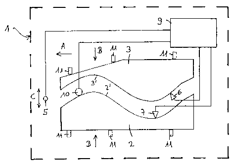
Embodiments of the invention will now be described in detail by way of
example, with
reference to the figure, which shows, highly schematically, a welding
apparatus for
carrying out the method.
The figure shows, highly schematically, a welding apparatus 1 in which two
sheets 2 and
3 to be welded together by means of a laser beam 5 are arranged. In the
position
shown, the sheets are held with their welding edges 2' and 3' spaced apart
from one
another prior to entry into the welding zone. The sheets are lying on a
conveyor device
(not shown) by means of which they can be carried through the welding zone in
the
direction A. Laterally the sheets are held by guides 11. In the spaced-apart
position
shown, each sheet edge 2' and 3' can be tracked by a sensor 6, 7 to detect its
precise
line. Instead of two sensors, it would also be possible to provide a single
sensor which
would sense first one edge and then the other. Instead of a mechanical sensor,
an

CA 02362713 2001-08-16
3
optical edge-line detecting system, or one based on some other sensing
principle, could
be provided. The sensors 6, 7 are guided along the respective edges by
traversing
means which are not shown, and signal the line of the respective edges to a
control unit
9. This unit records the precise lines of the two edges, and compares them
with each
other. The control unit 9 is able to determine from the line of the edges
whether the gap
will be within the permissible maximum when the edges are brought together for
welding.
If this is confirmed to be the case, the two sheets can be pressed together,
without
further reworking, by the guides 11, which move in the direction of the arrows
B, and in
this abutting position the two sheets are traversed in the direction of the
arrow A and
welded under the laser beam 5, which impinges on the gap from above or from
below. If
the line of the edges 2' and 3' is - as indicated in the figure - other than
straight, the laser
beam is made to track the gap by displacement in the direction of the arrow C.
In this
case, the control unit for the laser beam 5, which may be the control unit 9
or a separate
control unit connected to the control unit 9, may use the edge line detected
by means of
the sensors as the basis for controlling the laser beam 5. This control based
upon the
actual line of the edge or gap may replace or supplement the optical gap
detection which
has normally been used hitherto.
If, however, the control unit 9 finds, at the edge detection stage, that the
gap cannot be
kept within the permissible maximum if the edges 2' and 3' are joined together
in their
existing form, the control unit 9 identifies one of the edges as the dominant
or datum
edge, and controls the adjustment of the other edge by a machining tool 10 to
match it to
the datum edge. The datum 8 is chosen so as to incur the smallest possible
amount of
machining for the other edge. The machining tool provided may be e.g. a roller
10 which
presses on the edge to be machined so that the edge yields under pressure and
is
deformed accordingly. In this case the machining tool 10 may be displaced
along the

CA 02362713 2001-08-16
4
edge, applying varying pressure thereto. The corresponding mechanical,
pneumatic or
hydraulic actuating device for the roller 10 is not shown in the figure.
Pressing with a
roller is the preferred method of machining, as it produces no swarf, and the
squeezing of
the affected sheet edge does not hinder, and may possibly even assist, the
welding
process. On its own, pressing can produce an alteration to the edge line of
around 1/10
mm, which is sufficient for the present purpose. Nevertheless, other known
machining
methods, such as milling or grinding for example, may also be used. When the
machined edge has been matched to the datum edge, the machining tool 10 can be
withdrawn, and the two sheets are, as before, pressed together by the
positioning means
11 in the direction of the arrows B, and led by the conveyor means under the
laser beam
in the direction of the arrow A. In this case also, the movements of the laser
can be
controlled on the basis of the edge data.
If, after recording the lines of the two edges, the control device 9 finds
that machining the
two sheets with the tool 10 would fail to bring them sufficiently into
register, within a
specified time, for the permissible gap to be adhered to, machining is not
initiated, and
one sheet is discarded. This can be done by running one sheet out of the
welding
machine in direction A, or in the opposite direction, or sideways from the
welding
machine. The discarded sheet can be scrapped if the position of its edge lies
outside a
specified maximum deviation from a required edge position. If this is not the
case, then
the discarded sheet can be conveyed back to a sheet stack from which it will
later again
pass into the welding machine, along with another sheet. In this case, the
combination of
the two edge lines may result in a pairing whereby the permissible gap can be
comfortably adhered to.

CA 02362713 2001-08-16
The method and apparatus which have been indicated permit simple and rapid
pairirig of
sheets for the fabrication of tailored blanks in the welding machine. The
method is
especially preferred where the gap, or the line of the weld seam, is not
straight.

Representative Drawing
A single figure which represents the drawing illustrating the invention.
Administrative Status

2024-08-01:As part of the Next Generation Patents (NGP) transition, the Canadian Patents Database (CPD) now contains a more detailed Event History, which replicates the Event Log of our new back-office solution.

Please note that "Inactive:" events refers to events no longer in use in our new back-office solution.

For a clearer understanding of the status of the application/patent presented on this page, the site Disclaimer , as well as the definitions for Patent , Event History , Maintenance Fee  and Payment History  should be consulted.

Event History

Description Date
Inactive: IPC expired 2014-01-01
Inactive: Correspondence - MF 2010-08-10
Time Limit for Reversal Expired 2010-02-15
Letter Sent 2009-02-16
Grant by Issuance 2007-11-13
Inactive: Cover page published 2007-11-12
Pre-grant 2007-08-31
Inactive: Final fee received 2007-08-31
Notice of Allowance is Issued 2007-05-16
Letter Sent 2007-05-16
Notice of Allowance is Issued 2007-05-16
Inactive: IPC removed 2007-04-26
Inactive: Approved for allowance (AFA) 2007-04-03
Inactive: IPC from MCD 2006-03-12
Letter Sent 2005-01-05
Request for Examination Requirements Determined Compliant 2004-12-16
All Requirements for Examination Determined Compliant 2004-12-16
Request for Examination Received 2004-12-16
Inactive: First IPC assigned 2002-01-29
Inactive: Cover page published 2001-12-28
Letter Sent 2001-12-24
Inactive: First IPC assigned 2001-12-23
Inactive: Notice - National entry - No RFE 2001-12-22
Application Received - PCT 2001-12-10
Application Published (Open to Public Inspection) 2000-09-14

Abandonment History

There is no abandonment history.

Maintenance Fee

The last payment was received on 2007-01-23

Note : If the full payment has not been received on or before the date indicated, a further fee may be required which may be one of the following

  • the reinstatement fee;
  • the late payment fee; or
  • additional fee to reverse deemed expiry.

Please refer to the CIPO Patent Fees web page to see all current fee amounts.

Owners on Record

Note: Records showing the ownership history in alphabetical order.

Current Owners on Record
ELPATRONIC AG
Past Owners on Record
BRUNO KAEGI
ROMEO BUCHER
Past Owners that do not appear in the "Owners on Record" listing will appear in other documentation within the application.
Documents

To view selected files, please enter reCAPTCHA code :


To view images, click a link in the Document Description column. To download the documents, select one or more checkboxes in the first column and then click the "Download Selected in PDF format (Zip Archive)" or the "Download Selected as Single PDF" button.

List of published and non-published patent-specific documents on the CPD .

If you have any difficulty accessing content, you can call the Client Service Centre at 1-866-997-1936 or send them an e-mail at CIPO Client Service Centre.


Document
Description 
Date
(yyyy-mm-dd) 
Number of pages   Size of Image (KB) 
Representative drawing 2001-12-27 1 8
Abstract 2001-08-16 1 48
Description 2001-08-16 5 199
Drawings 2001-08-16 1 13
Claims 2001-08-16 2 56
Cover Page 2001-12-28 1 35
Representative drawing 2007-10-16 1 9
Cover Page 2007-10-16 1 38
Reminder of maintenance fee due 2001-12-24 1 111
Notice of National Entry 2001-12-22 1 193
Courtesy - Certificate of registration (related document(s)) 2001-12-24 1 113
Reminder - Request for Examination 2004-10-18 1 121
Acknowledgement of Request for Examination 2005-01-05 1 176
Commissioner's Notice - Application Found Allowable 2007-05-16 1 162
Maintenance Fee Notice 2009-03-30 1 170
PCT 2001-08-16 10 317
Fees 2003-01-24 1 30
Fees 2002-02-06 1 31
Fees 2004-01-20 1 28
Correspondence 2007-08-31 1 41
Correspondence 2010-08-10 1 49