Note: Descriptions are shown in the official language in which they were submitted.
CA 02362958 2001-08-15
WO 00/49714 PCT/US00/03760 - -
ME"I'fiOD AND APPARATUS DETERMINING POSITION OF A MOVABLE BARRIER
BACKGROUND OF THE INVENTION
1. Field of the Invention
The invention relates to operators for movable
barriers, such as rolling shutters, retractable awnings,
gates, garage doors, overhead doors and the like, and more
particularly to operators which can determine-the absolute
position of the barrier at all times, including after a
power outage and subsequent manual relocation of the
barrier.
2. Description of Related Art
One of the problems which must be addressed in
designing and engineering operators for movable barriers is
the provision of barrier position detection. Most
electronic positioning systems used in barrier operators
keep track of the barrier's position by incrementing a
position counter during one direction of travel and
decrementing the position counter during the opposite
direction of travel. This can cause errors if there are
missed pulses or extraneous pulses during travel (such as
from slippage of the barrier or motor).
Some barrier position detection systems employ a pass
point. The pass point corresponds to a fixed location on
the barrier, so that whenever the barrier moves past the
pass point, the position detector is normalized or
calibrated. By normalizing or zeroing out the position
detector (or counter), the effects of missed pulses or
slippage are eliminated. Some systems employ multiple pass
points which provide further error removal capability. The
CA 02362958 2001-08-15
WO 00/49714 PCT/US00/03760
- 2 -
pass point is a good solution in most situations, such as
for garage door operators, which seldom move manually.
A more significant problem can occur in motorized
awnings or rolling shutters. The rolling shutter assembly
is frequently installed in a housing which is built into a
wall. If power goes out on a rolling shutter system, the
user will frequently move the rolling shutter manually to
either open or close it. The power is off, but the gears of
the positioning system movewithout power applied to assure
manual override of an electric system for the purpose of
power failures. Some users may also decide for convenience
to move the shutter manually. When power returns, if the
rolling shutter has been manually moved past all pass
points, the operator, not encountering the pass point
reference, may cause the rolling shutter to continue to move
completely into the housing necessitating removal of the
shutter from the housing. Removal of the rolling shutter
from the housing frequently means removing a portion of an
interior wall.
There is a need for a movable barrier operator with a
position indicating system that provides the absolute
position of the barrier, even after power outages or after
the barrier has been moved manually. There is a need for a
movable barrier operator which can unambiguously determine
the position of the barrier after power is applied. There
is a need for a movable barrier operator which can
unambiguously determine the position of the barrier
regardless of direction of travel.
SUMMARY OF THE INVENTION
A barrier operator position detector includes a first
rotary member which is encoded to generate a first N bit
subcode selected from N sequential bits of a M bit code
word. The first N bit subcode has the property that every
selected subcode of N sequential bits of the M bit code word
has a unique value. N is greater than 1 and preferably 5.
CA 02362958 2001-08-15
WO 00/49714 PCTIUSOO/03760 - 3 -
M is greater than N and preferably 32. A second rotary
member is encoded to generate a second N bit subcode
selected from N sequential bits of a M-1 bit code word, the
second N bit subcode also has the property that every
selected subcode of N sequential bits of the M-1 bit code
word has a unique value (preferably M-1 is 31). A
controller, responsive to the first subcode and the second
subcode, generates a 2N bit multibit (or two N-bit subcodes)
code. The 2N bit multibit subcode is representative of a
unique position output, which can be decoded into a unique
position of the barrier along its travel.
A movable barrier operator according to the invention
includes an absolute position detector which provides a
unique value for each position of the barrier along its path
of travel. The absolute position detector employs two
binary serial streams and one clock stream. After the first
five cycles of the clock stream, the binary serial streams
can be decoded by a microprocessor or other processor to
produce an absolute position indication. Every clock edge
produces a new absolute position value along the path of
travel.
The absolute position detector employs three wheels;
two data wheels and a clock wheel driven by a pinon. Each
wheel rotates near a wheel state detector which produces
digital signals comprising bit streams. Preferably an
infrared emitter-sensor pair is used as the wheel state
detector. However, any electromechanical system which
produces a digital signal comprising bit streams, such as
Hall sensors, laser discs, and so on, may be used. For
convenience, the absolute position detector of the invention
will be described in detail with reference only to the
infrared emitter-sensor embodiment.
In the preferred embodiment, two of the wheels are data
wheels or gears and have teeth distributed around their
outer portions. One wheel has 32 teeth, the other wheel has
31 teeth. Each tooth of each data wheel has a corresponding
CA 02362958 2001-08-15
WO 00/49714 PCT/US00/03760
- 4 -
data bit formed in the wheel before the tooth. Each data
bit represents a single binary data bit. A space formed
below a tooth represents a digital low; a solid area formed
below the tooth represents a digital high. The 32 teeth
wheel has a 32 bit binary stream formed in it. The stream
is uniquely defined so: that any consecutive 5 bits in the
stream are different from any other consecutive 5 bits in
the stream, including the rollover stream. The 31 teeth
wheel is similarly defined,,except the 31 teeth wheel has
the same bit binary stream as the 32 bit wheel, with one bit
missing.
Since the 32 teeth wheel and the 31 teeth wheel have
different numbers of teeth and are driven by the same
pinion, they rotate at different speeds. The pinion is
driven externally by a gearing system that is driven by the
motor. The motor can rotate clockwise or counterclockwise,
so the pinion can also turn in both directions. Since the
motor is bi-directional, an attached load comprising a
barrier such as a door, awning, shutter or gate can move in
either of two opposite directions. Preferably direction of
travel information is obtained by storing the commanded
direction of travel (i.e., the user commands the door tQ
open by pushing the open button or to close by pushing a
close button).
The movable barrier is operated through linear linkage
of the load to the motor such as a trolley, or through
rotational linkage to the motor, where the load is wound
around the entire operator unit, such as in a rolling
shutters. Since the two data wheels rotate at different
speeds (because of the different number of teeth), the two
binary streams have different repeat rates. This means that
a given 5 bit stream from the 32 teeth wheel will not
combine with the corresponding 5 bit stream from the 31
teeth wheel until 31 more revolutions of the 32 teeth wheel,
or vice versa. In other words, a total of 31 x 32 = 992
unique two word values are possible without a rollover or
CA 02362958 2001-08-15
WO 00/49714 PCT/USOO/03760 - 5 -
repeated position concern. 992 unique positions is large
enough to provide absolute position along a part of a
movable barrier in most situations. An extra data wheel may
be added for more positions (i.e.,
32 x 31 x 30 = 29,760 positions). This mechanical linkage
also means if the unit is moved manually, the 31 bit wheel
and the 32 bit wheel will move, storing or representing for
later reading by the controller, the position of the awning,
door or shutter.
The third wheel is a clock wheel and is used to provide
a clock signal for the position detecting system to enable.
proper sampling of the data wheel bit streams. The clock
wheel includes 32 equally spaced openings. The clock wheel
provides a digital low pulse signal when the center of a
data bit on the 32 teeth wheel lines up with the center of a
data bit on the 31 teeth wheel and when these.centers are in
line with the IR sensors. The clock signal is provided to
the microprocessor which uses the clock signal as an
interrupt to sample binary data from emitter-receiver pair
associated with each data wheel. After the first 5 clock
cycles, each data wheel has output a 5 digit binary stream,
which when combined, gives 2 five digit binary numbers.
This 5 digit binary number pair is decoded by the
microprocessor which calculates an absolute position.
Thereafter, every clock cycle triggers the sampling of a new
binary digit from each wheel, the stored 5 bit binary number
pair is updated, and a new absolute position of the barrier
is determined.
The movable barrier operator according to the invention
with absolute position detector (or encoder system) provides
many advantages. It provides the absolute position of the
barrier for every pulse edge of the clock signal from
positioning gears turned by motor's gearing system. Shortly
after power is applied to the motor, the clock wheel would
CA 02362958 2001-08-15
WO 00/49714 PCT/US00/03760
- 6 -
have produced 5 pulses. After 5 pulses, the encoder system
determines the absolute position of the barrier. The
enco-der system can provide direction of travel after six
pulses of the clock wheel. The encoder system discriminates
false or unwanted pulses to prevent false positioning.
An absolute position is always provided shortly after
power is applied (after 5 pulses and the first 5 digit
binary pair is obtained), regardless of the stored value of
the last position and regardless of where the barrier may
have been moved manually. The absolute position detector
also provides an opportunity for the system to do a'validity
check for every newly calculated position (i.e., by checking
the absolute position between successive data streams, the
direction of travel can be ascertained). It should also be
noted that no presetting of the wheels prior to
installation/ operation is required.
Additional advantages and features of the invention may
be appreciated from a perusal of the specification,
including claims in light of the accompanying drawing.
BRIEF DESCRIPTION OF THE DRAWINGS
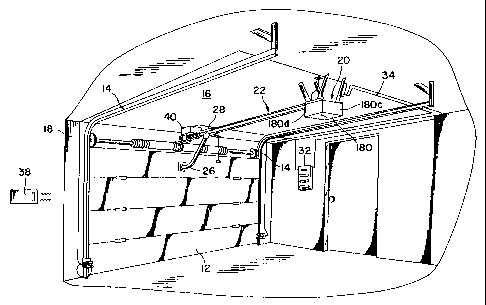
Fig. 1 is a perspective view of a garage door operating
system in accordance with an embodiment of the invention;
Fig. 2 is a perspective view of a rolling shutter
operating system in accordance with an alternative
embodiment of the invention;
Fig. 3 is a perspective view of the tubular motor
assembly of Fig. 2;
Figs. 4 and 5 are two exploded perspective views of the
location of the absolute position detector assembly shown in
Fig. 3;
Fig. 6 is an enlarged perspective view of the absolute
position detector assembly of Fig. 4;
CA 02362958 2001-08-15
WO 00/49714 PCT/USOO/03760 - 7 -
Fig. 7 is a graph of the 32 bit data streams produced
in each of the 31 bit wheel and 32 bit wheel;
Fig. 8 is an example calculation of position using the
31 bit wheel and the 32 bit wheel;
Fig. 9 is a flow chart of the routine run by the
controller to sample the 5'bit data streams;
Fig. 10 is a flow chart of the RPM routine used by the
controller to sample the 5 bit data streams; and
Fig. 11 is a schematic diagram of the electronics
controlling the rolling shutter head unit of Fig. 2.
DETAILED DESCRIPTION OF THE PREFERRED ~MBODIMENTS
Referring now to the drawings,,and especially to
Fig. 1, a movable barrier operator embodying the present
invention is generally shown therein and identified by
reference numeral 10. The movable barrier operator 10 is
employed for controlling the opening and closing of a
conventional overhead garage door 12 of a garage 13. The
garage door 12 is mounted on guide rails 14 for movement
between the closed position illustrated in Fig. 1 and an
open or raised position. The garage 13 includes a ceiling
16 and a wall 18 defining an opening blocked by-garage door
12. As shown, guide rails 14 are mounted to wall 18 and
ceiling 16 of the garage 13 in a conventional manner.
A power drive unit or head, generally indicated at 20,
is mounted to the ceiling 16 in a conventional manner. An
integrated drive rail 22 extends between the power drive
unit 20 and the garage wall 18. As can be seen in Fig. 1,
one end of integrated drive rail 22 is mounted to a portion
of the garage wall 18 located above the garage door 12. An
operator arm 26 is connected at one end to the garage door
12 and at the other end to a trolley 94 mounted for movement
back and forth, along the integrated drive rail 22. As will
be seen herein, a motor in the power drive unit 20 propels
the trolley 94 in a desired manner to raise and lower garage
CA 02362958 2001-08-15
WO 00/49714 PCT/US00/03760
- 8 -
door 12 via the coupling of the trolley 94 and the operator
arm 26 to the garage'door 12.
A push button control unit 32, which includes
an electronic controller and a keypad, is coupled by
electrical conductors 34 to the power drive unit 20 and
sends signals to the power drive unit, controlling operation
of the drive motor therein. Preferably, the power drive
unit 20 also includes a conventional radio receiver (not
shown) for receiving radio signals from a remote control
transmitter 38. An optional auxiliary power drive unit 40
is shown coupled to one end of integrated drive rail 22,
being mounted on wall 18, atop door 12. If desired, opera-
tional flexibility of the integrated drive rail assembly may
allow relocation of the main drive unit to a point adjacent
the door.
Referring now to Fig. 2, a barrier operator system
employing an absolute position detector is employed for
controlling the opening and closing of a conventional
rolling shutter 112. The rolling shutter is mounted on
guide rails 114 for movement between the closed position
illustrated in Fig. 2 and an open or raised position. The
wall 118 defines an opening blocked or covered by rolling
shutter 112. As shown, guide rails 114 are mounted to wall
118 in a conventional manner.
A power drive unit or head, generally indicated at 120,
is mounted to the top of frame 110 in a conventional manner.
Although the head unit is shown as being mounted on the
exterior, as noted above, in many applications, the head
unit is built into the wall so the user sees only the
shutters. In the two views shown in Fig. 2, the head unit
120 is shown mounted on opposite sides of the top of frame
110. As will be seen herein, a motor in head unit 120
propels a sleeve or tube 142 to raise and lower rolling
shutter 112 via the coupling of sleeve 142 to rolling
shutter 112.
CA 02362958 2001-08-15
WO 00/49714 PCT/US00/03760
- 9 -
Control for head unit 120 may be as described above for
garage door operator 20, i.e., using a push button control
or a keypad mounted at another location on a wall.
Additionally, head unit may also include a conventional
radio receiver (not shown) for receiving radio signals from
a remote control transmitter. If desired, the head unit 120
may be mounted on either side of the frame 110.
As shown in Figs. 3, 4 and 5, head unit 120 includes a
tubular housing 138 and end section 122 and 134. Within the
housing 138 is the motor 130 which includes an output shatt
131 coupled at one end to end section 134 and at the other
end to driving gear assembly 132. The output from gear
assembly 132 is provided to output ring 140, which is
fixedly attached to outer sleeve 142. Rolling shutters are
attached to outer sleeve 142, so that when motor 130 runs,
outer sleeve 142 rotates, causing rolling shutters to open
or close (depending on the direction of rotation of motor
130).
Outer sleeve 142 is also fixedly attached to ring 136
Ring 136 drives absolute position detector assembly 124.
Position detector assembly 124 is coupled to control'board
144. Control board 144 contains the electronics for
starting and controlling motor 130 (see Fig. 11). Capacitor
126 is used to start motor 130 (described below). A brake
128 is provided to slow motor 130 when the rolling shutters
are approaching a limit position.
Referring to Figs. 6 and 7, absolute position detector
assembly 124 includes a clock wheel 206, which is attached
to axle 212 for rotation therewith. Axle 212 rests in
supports 210, and freely rotates therein, which are attached
to board 140 by legs 240. Clock wheel 206 includes 32
equally spaced openings 230. The clock wheel 206 provides a
digital low pulse signal when the center of a data bit on
the 32 teeth wheel 202 lines up with the center of a data
bit on the 31 teeth wheel 204 and when these centers are in
line with the IR sensors -- through an opening 230 (not
CA 02362958 2001-08-15
WO 00/49714 PCT/US00/03760
- 10 -
shown). The clock signal is provided to the microprocessor
which uses the clock signal as an interrupt to sample binary
data from each data wheel. 32 bit wheel 202 is attached to
axle 212 for rotation therewith. Each complete rotation of
the 32 bit wheel 202 corresponds to one complete rotation of
clock wheel 206. 32 bit wheel 202 includes 32 teeth or
gears 220, which are driven by pinion 252 (see Fig. 4) which
is driven by ring 136. 31 bit wheel 204 includes 31 teeth
or gears 222 which are also driven by pinion 252. 31 bit
wheel 204 freely spins about axle 202. One turn of the 32
bit wheel 202 corresponds to 32/31 turns of the 31 bit wheel
204.
A unique bit stream pattern is formed in each of 32 bit
wheel 202 and 31 bit wheel 204. Beneath the teeth 220 are
solid areas 226 and spaces 224. A space under a tooth 220
corresponds to a 0; a solid area 226 correspond to a 1. The
exact pattern is shown in Fig. 7. The first row of pulses
are the 32 pulses generated by the clock wheel 206. One
complete revolution of the clock wheel generates 32 low
pulses, representing sample time. The 31 bit wheel has
solid and spaces areas which correspond to a 31 bit data
stream: 1111000001110100010010101100110 as shown in the.
second row of Fig. 7. For every one complete revolution of
the clock wheel, the 31 bit wheel produces the unique 31 bit
data stream plus one rollover bit. The 32 bit wheel 202
generates the data stream: 11111000001110100010010101100110,
which is the same pattern as the 31 bit data stream with the
addition of an extra 1 at the beginning of the stream. This
data stream is constant for every revolution of the clock
wheel.
In the 32 bit stream, no five consecutive bits are
repeated anywhere else in the stream. This is true for the
31 bit data stream. When the unit is powered for movement,
five consecutive (or sequential) bits are sampled from each
wheel. The decimal value is calculated for each 5 bit
number. The lookup table A (attached hereto) is used to
CA 02362958 2001-08-15
WO 00/49714 PCT/US00/03760
- 11 -
convert the 5 bit number to a decimal number. Then a
mathematical operation is performed on the two converted
numbers (from the 31 bit wheel and the 32 bit wheel) to
produce an absolute position.
Referring to Fig. 7, if the unit were powered up with
the wheels aligned as shown in Fig. 7, the first 5 bit data
stream sampled would be: 11110 for the 31 bit wheel and
11111 for the 32 bit wheel. In the next clock cycle, after
rotation of 1/32 of the clock wheel a clock pulse is
generated, the 31 bit wheel produces 11100 and the 32 bit
.wheel produces 11110. Continuing for 32 1/32 steps, or 32 5
bit frames, each sequential or consecutive 5 bit data stream
produced by each wheel is unique.
An example calculation is shown in Fig. 8. A 5 bit
data stream is sampled from each of the 31 bit wheel and the
32 bit wheel. In this example, the 31 bit wheel produces
the 5 bit data stream: 01000. The 32 bit wheel produces the
5 bit data stream 10101. These numbers convert to 08
(Lookupi) 21 (Lookup2), respectively, using the lookup table
A. 12-20 = -8. If the result is negative, add 31 (Same as
modulo 31 arithmetic). Apply the mathematical formula:
(Result x 32) + Lookup2 = Absolute position. This gives an
absolute position of 756 out of 992 possible positions along
the path of travel.
The calculation of absolute position is performed in
two interrupt routines by the controller. The first
interrupt routine samples the clock and data wheels and
generates the next bit to be used in the sliding window or
sliding 5 bit data stream. When the clock wheel generates a
digital low pulse, the controller executes the absolute
position routine, shown in Fig. 9. Referring to Fig. 9, at
step 300, the routine checks if the IR sensor and detector
are operational. If the IR sensor and detector are not
operational, the-controller leaves the routine at step 318.
If the IR sensor and detector are operational, the routine
checks if the motor is on at step 302. If not, the routine
CA 02362958 2001-08-15
WO 00/49714 PCT/US00/03760
- 12 -
exits at step 318. If the motor is on, the routine checks
at step 304 if the clock pulse is going low, indicating the
beginning of a clock pulse. If not, the routine exits at
step 318.
If the clock pulse is going low, the routine sets the
state of the 31 bit wheel (WHEEL_31_STATE) register and the
state of the 32 bit wheel state (WHEEL_32_STATE) register
low in step 306. These registers store the value of the
next detected data bit. Atstep 308, the routine checks if
the 31 bit wheel stream is high. If yes, it sets the 31 bit
state register to high in step 310. If not, it continues to
block 312 where it checks if the 32 bit wheel stream is
high. If yes, it sets the 32 bit wheel state register to
high at step 314. If not, it calls the RPM routine, then
leaves the routine at step 318. The RPM routine takes the
current bit and uses it to create the next 5 bit data stream
for use in calculating the absolute position of the shutter.
Once the 5 bit streams are computed and stored, the
controller computes the absolute position as described above
and uses that information to keep track of where the door or
shutter is at each clock cycle and as a validity check for
direction of movement. It should be noted that if the
awning, door or shutter is moved manually, movement of the
door or shutter will drive the pinions moving the clock
wheel and 31 bit wheel and 32 bit wheel, so door/shutter
position is always mechanically recorded in the absolute
position detector assembly, ready for reading when the unit
is powered on.
After the current bit from each wheel is stored in the
appropriate register, the RPM routine is called. Referring
to Fig. 10, at step 340, the routine checks for the
direction of travel. This information is typically provided
by the user input when the user selects the up button or
down button. As noted above, this information can be
verified changed if the absolute position information does
not check out between successive clock pulses.
CA 02362958 2001-08-15
WO 00/49714 PCT/US00/03760
- 13 -
If the shutter is moving up the routine branches to
step 344. If the shutter is moving down, the routine
branches to step 342. Each step 342 and 344 forms the
appropriate sliding window (determines the consecutive 5
bits to be used in calculating the shutter position). In
step 344 the routine shifts the MASK_31 bits left. The
MASK31 bit mask is a window of all 31 bits the 31 bit
wheel. Then the least significant bit of the MASK_31 is
logically OR'd with the 31 bit wheel state register. Only
the first 5 bits of the MASK 31 mask (which contains the
entire 31 bit data stream represented on the 31 bit wheel)
are masked. Then the MASK 32 bit mask (which contains the
entire 32 bit data stream represented on the 32 bit wheel)
is shifted left one bit and the least significant bit of the
MASK_32 bit mask is logically OR'd with the value in the 32
bit wheel state register. Only the first 5 bits are masked.
This gives two shifted 5 bit data streams, one each from the
31 bit wheel and the 32 bit wheel, which are used to
determine the position of the shutter for that clock cycle.
In step 342 the routine shifts the MASK_31 bits right.
Then the 5th leas'L. significant bit of the MASK 31 is
logically OR'd with the WHEEL_31_STATE register. Then only
the first five least significant bits of the MASK_31 are
masked. The MASK_32 mask is shifted one bit right. Then
the MASK_32 mask is logically OR'd with the WHEEL_32_STATE
register.
In step 346 the routine uses a ROM.lookup table (see
Table A) to get a conversion for the numbers in MASK31 and
MASK_32. These digital numbers are stored in the variables
MASK_31 VALUE and MASK_32 VALUE. In step 348, the
difference between MASK 31 VALUE and MASK 32 VALUE is
calculated and the remainder from modulo 31 arithmetic
calculated. This result is called the DIFFERENCE. In step
350 the DIFFERENCE is multiplied by 32. Then MASK 32_VALUE
is added to the product. This number is the absolute
CA 02362958 2001-08-15
WO 00/49714 PCT/USOO/03760
- 14 -
position and is stored in the POS_CNTR. At step 354 the
routine ends.
_ The controller uses the POS_CNTR value in controlling
the operation of the shutter in its other routines, which
are not described.
A schematic of the control circuit located on control
board 142 is shown in Fig. 11. Controller 500 operates the
various software routines which operate the rolling shutter
operator 120. Controller 500 may be a Z86733
microprocessor. In this particular embodiment, the rolling
shutter is controlled only by a wall-mounted or unit-mounted
switch coupled via connector J2. Connector J2 has inputs
for up switched hot and down switched hot. In a rolling
shutter, the motor moves only when the user presses the
power direction switch connected to connector J2 and the
Triac Q1 is activated by the microcontroller. Pressing the
up or down switch applies power to the board via connector
J2 and provides various motor phase and direction
information to the controller 500. When the controller 500
permits travel, Triac Q1 enables the motor's neutral path.
The motor winding, which is then powered, will conduct
current.
However, the control circuit can be modified to include
a receiver so that the rolling shutter can be commanded from
a remote transmitter (as described above). Power supply
circuit 190 converts AC line power from connector J2 into
plus 5 volts to drive the logic circuits and plus 16 volts
for a voltage supply to the phototransistors Q4, Q5, Q6.
Upon receipt of a rolling shutter movement command
signal through J2, the motor is activated. Feedback
information from the motor and AC power is provided from J1
and applied to U3:A, U3:B, U3:C and U3:D. The outputs from
U3:B and U3:D provide up and down phase information to pins
P26 and P25 respectively. The outputs from U3:A and U3:C
provide up and down direction to pins P21 and P20,
respectively.
CA 02362958 2001-08-15
WO 00/49714 PCT/USOO/03760 - 15 -
Crystal CR1 provides an internal clock signal for the
microprocessor 500. EEPROM 200 stores the information such
as limit flags, force flags, learn mode flags, etc. The IR
signal break from clock wheel 206 drives Q5 which provides
an input to signal P31. Wheel 31 drives Q4 which provides
an input signal to P30. Wheel 32 drives Q3 which provides
an input signal to P33.
Table A attached hereto is the lookup table described
above.
Exhibit A (pages A1-A21) attached hereto include a
source listing of a series of routines used to operate a
movable barrier operator in accordance with the present
invention.
As will be appreciated from studying the description
and appended drawings, the present invention may be directed
to operator systems for movable barriers of many types, such
as fences, gates, shutters, awnings, garage doors, overhead
doors and the like.
While there have been illustrated and described
particular embodiments of the invention, it will be
appreciated that numerous changes and modifications will
occur to those skilled in the art, and it is intended in the
appended claims to cover all those changes and modifications
which fall within the true spirit and scope of the
invention.
CA 02362958 2001-08-15
-
WO 00/49714 _ 16 _ PCT/USOO/03760
Di ital stream from Data Bit Wheel MASK_31 or MASK_32 Vafue
.~C:Sr:=.ti.i{.yi:lp.~...' : ~...: '= .
vwr Look-u #
r:: ~::: =~.4ac:ax'g<'~ 3: ~~ '' nyti.~i;s.J.o:r;':: Previous 5 bitS for MASKS
;:'6~iwn,t.<...:,Rn ., ~y?== i.4:r ~i~n Ti
~~:~=iin:'arr=:lir::.'Y.r':'r:'~
':=v~J.L'r::f:.v;'ri:wwn,p~;~:y,~::'::::.='y+i.
converted to a decimal #.
~_~; ~.N'f'.. v,~i,6.. :#;i~cr.v:=:a:c:
.~ . ~:
:...,~H=.;; ~; =
::.Y:~S:stT'.,:E~rh,~ov:,~fi..',r.~x:="';Y~:y::'.o< .E,X=:.',.': ~''T'
=:7..:'=o:<:'=='i+'::; ' _
...:.:... ...::... . .:i :.~=..:....::..: . . .~':
30 0
. :3::;t:e:~,o..,.:'aao.,..~'.:: .:~=.. vn4t030: '
fi}~i::OL:Q~If.lr~:~,p'o~or.~l':~~.;:;y:'': .
28 1
::pM~yO.. . .4.LwLtw';"vv".v....:.v. ..~ : ... P4.'M1.. n.vp;..=,.....r.. 24 2
.. ?s .'E.'bj:b9 ..<=.~;::=:S.:F,,R;;9:$.'F.=' 4i.5:S:o..',ed.at.wbw~q~;
e;S..S='i;
.<: = D~.
,.:.::............ <:,.:.
16 3
CO SF.'4'i~,Y~i~f'Z:p'a~....._.. ... '..=.....aS$:3.~5=.......'ry': i''
= .: . .
..: :: . .. . ~
: ,. =.. .
.:.
>.:: *fa::: ~:: :'2i$? y.i:b:~': iF :: ~='. OeYOS,
1 5
::i,ti::y'=E.#',e.~8=9:Yvw~i%i~~c:':3:'a;'i.':':::~.'..~~':3S'::';.e.
:.:.:~.;'ii=~: '~
3 6
~'.~SN ~:ti::=::Yi.'::TCi:~.C. . . . ... . v::: ~~2:'=
:34ii<vY':'.::Y.:.;.i4:::.~.
...r,}_S T.:.:.,H4;4S.Rb4;~jv.Y;, C= i,v.ivi:,,.~....,.'::;4: >=,;::::'-
r:,~';: 7 7
14 8
~''4:;2Yi.:::<~o~t::r';~.:: <=x=.;a :..:<...; 29 9
.h.:.:.:.:: =:.~.~i~ . .. ~...r
."~'::':' .:>:=:'<:~':'i:: !:......,.n
............
<=; %:::~' ?:S:Q.i:'~l.k:>::i:::~:;ic:y~:o~>:::
.>.: 26 10
::.....J.::.i::: ..:.
..i:::r.w.i~.~r.= = =:=
:.: i...i :..:.... ry... .. .. . ... n .
20 11
8 12
..ic . y:.;.; . .. . .,
,.=,., ~. ~.... . . .,,.......;...=~'~ .
17 13
2 14
4 15
9 16
18 17
19
.~m.x::='r't'P;-::=,;v;::<::;::;~:>::::: <:>::;::::::;..<:
::;~;::::::;:<::<:<: 21 20
::::?SO::~~o:~$'fi:::'c..:'>y:"i;'."':;:i:[ca=..:L$.? ~.;;=.
:G~::;::ciE:.~C:S..' 11 21
F:;{y':: :':::'=::
22 22
12 23
:<Y.3:=. 25 24
19 25
:. ..:.; ,.:.=:.;::..:..
:..:.. :
,...:;',..,.:...>.>p: ;:,::;,:::::>:<:>::: 6 26
;: >.:;:;: :: ; .; <'>:>..:>:.:; .;;:; =;;::;;:::1.;.';.::;: :: :.<:::' ::< F:
<< ::::::::..::: 13 27
1 27 28
1 23 29
1 15 30
1 31 31
1Pf A
CA 02362958 2001-08-15
WO 00/49714 _~ ~_ PCT/US00/03760
,~7x/4/( A
Last Modified Febuary 10, 1999.
; This is the Code for the Tubular Motor First Generation product.
There is no force ser,sir.g.
Get rid of RA.K TEST a-nd CHECRSUM.
Get rid of stop mode.
Take out WDT.
;***.******************************************~******,.**** ******.*****
****
Equate Statements
* * * * * * 1 * * R ~ R 1* * R * R * * * * * * * * * * * * * * R * * * * * * *
* * * * * * * * * * * * * * * * * * * * * * * * * R * * * * *
****
globals on
PO1X-INIT equ 00000100B
P22:_INI'T . equ 01100011B
P3X.-IhIT .equ 0000C001B
PO1S_INIT equ 00001010B
P2S_INIT equ 00000000B
P3S_INIT equ 00C000003
P2M_EEOUT equ 11111011B ; Mask for outputting data to EEPROK
P2M_EEIN .eqa 0000G100B ; Same for input
-----------------------------------------------------------------------
GLOBAL REGISTERS
-----------------------------------------------------------------------
~******f**t***7t**********t****.*******************rt*******************R*
****
LEA~N EE GROUP REGISTERS FOR LOOPS ECT
* * * * * * * * * * R R 1 * * * * * * * * * * R * * * * * * * * * * * * * * *
* * * * * * * * * * * * * * * * * * * * * 'k * * * * R R R * * *
****
LEARNEE_GRP equ 20H
P2M_SHADOW . equ LEAR:'T~'E_GRP+O ; Mask for mode of P2
TEMP equ LEARNEE_GRP+2
MTEMPH equ LEARNEE_GRPT6 ; memory temp
MTEMPL .eqti LEARNEE_GRP-7 ; memory temp
MTE-VS equ L :AR23EE_GRP+8 memory temp
SERIAL . equ I.EI,.Rh'EE_GR?+9 ; serial data to and from nonvol
memory
ADDRESS equ LEF,R.'QEEE_GRP+10 ; address for the serial nonvol
memory
temp equ r2
mte:nph equ r6 ; memory temp
mtettlpl . equ r7 ; memory tamp
mterap equ r6 ; memory temp
serial .ecr-, r9 ; serial data to and from nonvol memory
address equ r1C ; address for the serial nonvol memory
.**1t******f*'*t'k**R*1tt*t'rM*R***R*******M*T*******************RRRRR
MAIN GRP . eqL 3 OH
CA 02362958 2001-08-15
WO 00/49714 PCT/USOO/03760 -18-
UP_LIMIT_F? equ N.tilti_GRPTO ;** upper limit high byte
UP_LIV.IT_L .equ MAIN_GR?+l ;** upper limit low byte
UP_LI2:IT . equ MA=N_GRP+O ; upper limit word
DOWN_LIMY~_H equ MAlN_GRP+2 ; lower limit high byte
DOWiC_LIMIT_L equ MAIN_GRP+3 ;** lower limit low byte
DOWN_LIMIT .equ MAIN_GRP+2 ; lower limit word
POS_CNTR H equ N.AIN_GRP+4 ; position counter high byte
POS_CNTR_L equ MAIN_GRP+5 ; position counter low byte
POS_C.~TTR . eqs Xu,IN_GRP-4 ; position counter
POWEFi LFC equ MAIN_GRPT6 ; power line sampier
U?_LFC equ MAIN_GR?+7 ; Up Line Filter counter
DOWN_LFC equ MAIN_GRP+8 ; Down Line Filter counter
POWER DEBOUNCER equ MAIN_GRP+9 ; 4ms in a row a power on
UP_DEBOUNCER equ MAIN_GRP+10 ; (A) up debouncer
DOWN DEBO'JNCER equ MAIN_GRP+11 ; (B) dowr. debo=sncer
UP_AIQD_DOWN' equ MAIN_GRP+12 ; (C) 1 for up 2 for down
OFF_LFC equ MAIT_GRP+13 ;(D) 30ms = power off
LF_TIMER equ NAIN_GRP+14 ; (E) Line Filter Timer
MOTOR_FLAG equ N,AIr_GRP+15 ; (F) AA Hex when motor on
pos_cntr_h eqa r4 ; position counter high byte
pos_cntr_l equ r5 position counter low byte
pos_cntr equ rr4 ; position counter
MAIN_GRP_2 equ 40H
MASK_32 ..equ MAIN_GRP+16 ; (0) 5 bit mask of P33 stream
MASK_31 .eq-a N.AIN_GRP+17 ; (1) 5 bit mask of P32 stream
MASF,32 VALUE equ MAIN_GRP+18 ; (2) look up value for 32 bit wheel
MASK_31_VALUE equ MAIN_GRP+19 ; (3) look up value for 31 bit whee.L
LOOP_5 .equ MAIr GRP+20 ;(4j loop counter
MODULO equ N'AIr_GRP+21 ; (5) gives mod of difference
MASF(_ADDRESS_H . ecrL: N1aIN_G1P+22 ; (6) iiB of address of lookup value.
MASK_ADDRESS_L equ NhIN_GRP+23 ; (7) LB of address of lookup value.
MASK_ADDRESS eq-s MAIN_GRP+22 ; (6) address of lookup value.
RPM_HIGH_JOB . equ 1:F.IN_GRP+24 ; (8) rpm high debouncer
RPD:_LOW_DE . equ N.hIN_GR?+2 5;( 9) rpm low debouncer
WHEEL_31_DB equ MF,IN_GRP+26 ; (A) wheel 31 high db
WHEEL_32_DB equ MAIN_GR?+27 ; (B) wheel 31 high db
BIT_33 STATE .eql MF,:N_GRP+28 ; (C) set to 17 when high
BIT_32_STATE equ MA:N_GRP+29 ; (D) set to 17 when high
DIFFERENCE equ Mk=N_GRP+30 ; (E) MASI(_32 VALUE-MASK_31 VALUE
CLOCK_CYCLES equ MAIN_GRP+31 ; (F) number of RPM interrupts.
mask_32 value eq; r2 ; will contain lookup*value.
mask_31value eqa r3 ; will contain lookup value.
loop_5 equ r4 ; (F) loop counter
mask_address_h equ r6 ; contains HB of address of lookup value
mas:c_address_:. equ r7 ; contains LB of address of lookup va=ue
mask_address equ rr6 ; contains address of lookup value.
MAIN_GR?_3 equ 50H
DELAY_TiME-ER equ MAIN_GRP+32 ; (0) timer for relay enable de_ay
STOP_FLAG equ M.A.IN_GRP+33 ; (1) tells main loop to stop
START_FLAG .eqs NlF,IN_GRPT34 ; (2) flag for inc cour.t flag
LII/_IT_FLAG equ MAIN_GRP+35 ; (3) ** 033H for up OCCH for down.
UP_CUSHIOr_H eqs N.F.IN_GRP-36 ; (4) 100 positions past up limit
UP_CUSHION_L . ecr.1 N.F,IV_GRP+37 ; (5) 100 positior.s past up limit
CA 02362958 2001-08-15
WO 00/49714 PCT/USOO/03760 -19-
UP_C:JSHION equ MAIN_GRP+36 ; (4) 100 positions past up limit
70irj'N_CUSHION_H .ec~,u MF:IN_Gn:T3E ; (6) 100 positions past down limit
DOSA'N CUSHION_L equ Y-AIN_GRPT39 ; (7) 100 positions past down limit
DOk'K_CUS?iION eql :yI.Z_N _GR?T3c ; (6) 100 positions past down limit
POS_CNTR_-H_TEMP equ MAII\'_GRP+4C ; (8) temporary position value
POS CA'TR_L_TEMP equ MF:II~_GFtP+4: ; (9) temporary position value
POS_CNTR_TEMP . eq;: N'.,'-.,N_GRP+40 ; (8) temporary position value
MASK_32_TEMP MAIN_GRP-42 ; (A) temporary mask value
MASK_31_TEMP equ irlAIN_GRP+43 ; (B) temporary mask value
LEAR'V_F:,.AG equ MAIN_GR.P+44 ; (C) ** learn mode flag
FREE TRAVEL_FLAG equ MRIN_GRP+45 ; (D) ** flag for free movement
A11intOn equ N.AIN_GRP+46 ; (E) sets up interrupts
TAP_CNiR .eq,: biAI:V GR?T47 ; (F)
;************************************~**************~***********
CHECK_GRP equ 8011
check_s:utivalue equ 03DH
checl-sum . equ rO
rom-data . equ rl
test_adr_hi equ r2
test aos_lo equ r3
test adr . eq,: rr2
~**x*****õ***********.******.****,.******************************
STACKEND equ OAOti ; start of the stack
STACKTOP .ecla 236 ; end of the stack
csh equ 00G10000B ; chip select high for the 93c46
csl equ 1110111lB ; chip select low for 93c46
c=ock'r. .eq:: GCG:ICC.E ; cloc;c high for 93c46
clockl eqs 1111011?B ; clock low for 93c46
doh ecu 000CG100B ; data out high for 93c46
doi .e(T1 11111011'B ; na=a out low for 93c46
psmask eqs C100GuGGB ; mask for the program switch
csport equ P2 ; chip select port
dioport equ P2 ; data i/o port
clkport equ P2 ; clock port
psport ecu P2 ; prograrr, switch port
bSemoryTimer eqs 96
WA~_'CHDOG_GROLP ern: OFH
PCON . equ rO
SN:R . e c,: r 11
9,TDTN.R . e au r 15
FILL macro
.byte Or~Fh.
. ena-n
FILL10 macro
.byte CFFh
.byte OFFh
.byte OFF'--,
.byte Or'Fi:
.byte OFFh
.byte OFFh
.byte CFr:.
CA 02362958 2001-08-15
WO 00/49714 PCT/US00/03760
-20-
.byte OFFh
.byte OFFh
.byte OFFh
.endm
FILL50 macro
.byte OF Fh
. byte OFF:4
.byte OFFh
.byte OFFh
.byte vFFh
.byte OFFh
.byte OFFh
.byte OFFh
.byte OFFh
.byte OF= h
.byte OFFh
.byte OFFh
.byte OFFh
.byte OFFh
.byte OFFh
.byte OFFh
.byte OFFh
.byte OFFh
.byte OF_ h
.byte OFFh
.byte OFF-i
.byte OFFh
.byte OFFh
.byte OFFh
.byte OFFh
.byte OFFh
.byte OFFh
.byte OFFh
.byte CFFh
.byte OFFh
.byte OFFh
.byte OrFh
.byte OFF:
.byte OFFh
.byte OFFh
.byte OFFh
.byte OFFh
.byte OFFh
.byte OFFh
.byte OFFh
.byte OFFh
.byte OFF:
.byte OFF:z
.byte OFFh
.byte OFFh
.byte OFF:
.byte OFFh
.byte OFFh
.byte CFFh
.byte OFFh
. endn:
TRAP mac.o
jp start
7p starz
jp start
CA 02362958 2001-08-15
WO 00/49714 PCT/US00/03760
-21-
jp start
jp start
. endir
TRAP10 rr.acro
TIRA-r-
TRF,?
TRAP
TRAP
TRAP
TRAP
TR;~P
TRAP
TRAP
TRAP
. endm
*#ix*#trxx*yrnx*x**#x#*x*r*ttr,rx###,t~rtrixrvr****#*#*##*#x#,-
,ti*r*s.#x#wxxt,txxx
*
Interrupt Vector
Table
.xxx*~fnxxxxr*xx~ry.xxxxxxxxxx*xx~xxxxr#wxxx*xxx.*x##xxx#itxx#yrxxxxxxxxxxx
#
.orc 0000H
.word Fk.SE_INT ;IRQO, P3.2
.word FALSE_INT ;IRQ1, P3.3
.word FALSE_INT ;IRQ2, P3.1
.word FALS=_INT ;IRQ3, P3.0
word TID:ER: _I\ : ; IRQ4 , TO
.word FALSE__DIT ;1RQ5, Ti
.page
.org OGOCH
jp ~TART
DerEEL_TABLE:
.byte 004H
.byte C05E
.byte OOE.t
.byte 006ri
.byte OOFH
.byte C12H
.byte Oi~ti
.byte 007H
.byte OOCii
.byte 010H
.byte 0i3H
.byte 015H
.byte 017I:
.byte C1bH
.byte OOfi?:
.byte 01 LH
.byte 003h
.byte CCD:
CA 02362958 2001-08-15
WO 00/49714 PCT/USOO/03760 -22-
.byte O11H
.byte 019H
.byte OOBH
.byte 014H
.byte 016H
.byte Fi1DH
.byte 002Fi
.byte 018h
.byte OOAH
.byte O1CH
.byte OO1H
.byte 009ii
.byte 000H
.byte OlFH
.org 0101H
~*ttttttrtt~tttt**+.rtttt*ttttttt*txtt*ttttxtt*tttt,-tt*tt*ttttttttttttttt
REGISTER INITILIZATION
tttttttttttttt*.txtttttttttttttttttt+**t,.tttt*tttttt**ttttt*tttttttt,r*,-
t
start:
START:
di ; turn off the interrupt for init
ld RP,#WATCHDOG_GROLP
ld WDTN-R,#00000111B ; rc dog 100ms.
clr RP
WDT ; kick the dog
; clear the register pointer
xor P2, #10000000B ; toggle pin 3.
.tttttt~t**t*tt.*t.ttt*.t*.ttttt,..ttt*ttt,.ttttt.tt.*tttttttt*tt*tt**ttt~
*
;* PORT INITIAL=ZATION
.
ttt~R*if*rttt*it*tttt**tttttittttt*ertr*t~tltttttttttttwtttttttiRiktttttttkt*~t
rtlr
t
ld PO1M,#PO1M_ITIT ; set mode p00-p03 out p04-pO7in
ld P3M,#P3N,_INIT ; set port3 p30-p33 input analog
mode
p34-p37 outputs
ld P2M,#P2M_IhIT ; set port 2 mode
ld P2P!_SHADOW, #P2M_INIT ; Set readable register
ld P0,#PO1S_INIT ; RESET all ports
ld P2,#P2S_INIT
ld P3,#P3S_INIT
~t*tttt**ttttttt.~.tt*,+,.tttttttt*..tttt,.tttt**+ttttttttt*.~**ttttttttttt
t
Interr_a: RAu Test and Reset All RAM = mS
t
~tttt*,.tttttt*t*ttttt.~t**tttttt*tt*t*t..ttttttttt*t**t*ttttttt*ttttttt*
t
jp STACK
srp #0F0H ; POINT to control register group
ld r15, #4 ; r15= pointer (ninir,un of RAN)
CA 02362958 2001-08-15
WO 00/49714 PCT/US00/03760
-23-
write_again:
WID'I' ; kick the dog
xor P2, #1CC00000B ; togg:e pin 3.
ld rl4,#l
write_againi:
ld @r15,r14 ; write 1,2,4,8,10,20,40,80
cp r14,@r:5 ; then compare
jp ne,systerr,_erro=
rl r14
jp nc,write_againl
clr Qr15 ; write RAM(r5)=0 to memory
inc r15
cp r15,#240
jp ult,write_again
~*Y*****Y*Y**1r***YYYttYfYYrYY**YY*YY*****Y****Y****'!*****~7,~*Y**YYY**Y*kf
*
Checksum Test *
;
**1t*tf**Y****Yt****tr************Y*****f*Y***t4*****f*****tt*7r*k*tk**t******
*
CT=ir.CKSUNTES T :
srp #CHECK_GRP
ld test_adr hi,#CFH
id test_adr_lo,##OFFH ; maximum address=fffh
add_sum:
W:>T ; kick the dog
xor P2, #1~.OO00JOF ; toggle pin 3.
ldc rom data,@test_adr ;read ROM code one by one
add check_si:m,rom data ;add it to checksum register
decw tesz_adr ;increment RON_ address
jp nz,add_sum ; address=0 ?
cp check_sum,#caeck_sum_value
jp z,systeir,_ok ;check final checksum = 00 ?
syste-~_error:
and P0,#1111_011B ; turn on the led
jp systeir'error
.byte 256-check_sur'value
syste,ni ok:
h'DT ; kick the dog
xor P2, #10000000B ; toggle pin 3.
ld STACKEIv'D,#STACKTOP ; start at the top o: the stack
SETSTACFCLOOP :
ld @STACKENU,#01H ; set the value for the stack vector
dec STACKE2O ; next address
cp STACKEh'D,#STACKEA'O ; test for the last address
CA 02362958 2001-08-15
WO 00/49714 PCT/US00/03760
-24-
jp nz,SETSTACKLOOP ; loop till done
~YYYY+Y+'*Y+Y+Y:++*Y**+++rii***+****+rR*#****##*+**#*+**Y*+*+ir***atrt*nYVr**
*
YSTACK iNITI:.IZATION
*Y1l*+**.*-#** **+* * ****Yr* * *.:*** *11***r* * **+rt **rtF*41'***** ***
**** *+1f* ** * * *tk lF
STACK:
WDT ; KICK THE DOG
xor P2; #10000000B ; toggle pin 3.
clr 254
ld 255,#238 ; set the start of the stack
#*Y*Y++**tM+*+*Y**Y*++*++****+++**Y++****+**+Y++YY**z****++****++*~****+
+
*TIMER INITILIZATION
+*YY**Y*Y******+*+YYr*++*++***r*Y***~**~***+*Y*******+**+*+*********~~*
Y
TIMER:
ld PREO,#00010001B ; set the prescaler to 1/4 for 250Khz
ld TO, #OFAH ; set the counter to count 250 to 0
(TO=lms)
ld PRE1,#11111111B ; set the prescaler to 1/63 for 16Khz
id T1, tOF.H ; set the counter to count 255 to 0
(Tl=16ms)
ld TMt,#OOOOC111B ; turn on the TO timer.
.Y*YY****YY+*+*Y**Y*YYY**+*+*Y*Y+****+*Yt+*+YY**#*.***#****+**+*Y****++*#' .
~
*PORT INITIALIZAT_ON
YY*****=l*****ir+~rvlr*Y*YYirY***+++*+*+rt**+***+***Y+**+*r*++****+**++wY~**+
ld ?O1M,#PC1M_INIT j set mode p00-p03 out p04-pO7in
ld P3N',#P3M_:NIT ; set port3 p30-p33 input analog
mode
; p34-p37 outputs
ld P2M,#P2M_INIT ; set port 2 mode
id P2M_SHADOVJ, #P2M_INIT ; Set readable reg:ster
ld P0,#PO1S_INIT ; RESET all ports
ld P2,#P2S_INIT
id P3,#P3S_INIT
.Y+Y+Y+*YY#++**+#Y+++++*YYY*#+Y++*Y+Y++Yn+r#++Y+ir+w+**++Y*+++++Y*+*++~r+*
+
INITERRUPT INITILIZATION
.YYY*#**++++**YwY+*+++*r+**it****++*Y++Y****+++++****#++++*++++***++rtYryr+
*
SETINTERRUPTS:
ld IPR,#0010110=? ; set the priority to RPr.
ld INat, #0:010000B ; set IMR for TO interrupt only
ld IRQ,#11000000B ; set the edge clear int
CA 02362958 2001-08-15
WO 00/49714 PCT/US00/03760
-25-
* f * * * * 7r r r'Ir * * * * Yr * r * 11r * * r r 1t * * * * * * * * * * r 7r
: 1[ * * * * * * * * * * 7r * * * * * * * * r r * * Ir * * * * * * * * *
*
SET SMR & PCON
******rru*r******tff**::r*****tk****rtrx******************ttr*************
* *
ld RP, #WATCHDOG_GROJP
id SMR,#000111103 ; recovery source = P2 NOR 0:7
ld PCON,#1001011C.3 ; reset the pcon no comparator
output
; STANDARD emi mode
clr RP
***i**************.-r********r********~*******r*************+f**********k
VARIALBE INITILIZATION
~*************rrr******~*****4************************************r*****
*
WDT ; KICK THE DOG
xor P2, #10000000B ; toggle pin 3.
ld POS_CNTR_H, #00
ld POS_CNTR_L, #00
ld LF_TIMER, #00
ld OFF_LFC, #00
ld UP_LFC, #00
id DODkT'_LFC, *00
ld POWER_LFC, #00
ld MOTOR_FLAG,#00
id DELAY TIMER, 000
ld STOP_FLAG, #00
1 C START=_FLAG,V0
1 d UP_.AND_DOLtiZv,# C 0
id POtti'ER_DEBOUNCER, # 0 0
_d UP_DEBOUNCER, #00
id DOk'N_DEBOL'NCE:c, #00
ld T'AP_CNT1, #00
id MASK_32, 400
ld MASK_31, #00
id MASK_32 VALUE, #0C
ld MASK_31 VALUE, *00
id DIFFERENCE, #00
ld CLOCK_CYCLES, #00
ld FREE_TRAVEL_FLAG, #C0
ld LIMIT_FLAG, 000
ld UP_CUSHION_H, #00
la UP_CUSHION_L, 400
id DORN_CUS310N_H, 000
id DOWN_CUSHION_L, #00
ld POS_CNTR_H_TEMP, #00
ld POS_CNTR_L_TEMP, #00
ld MASI{_32_TEMP, 000
1 d MASX_31_TrNP, #00
ld RPM_HIGE_DB, #11
id RPM_LOW_DB, #00
id WHEEL_31_DB, *00
ld WHEEL_32_DB, 000
ld BIT_31_STATE, #00
CA 02362958 2001-08-15
WO 00/49714 PCT/USOO/03760 -26-
id BIT_32_STATE, #00
id LEAR2;_FLAG, #02
ld UP_LIMIT H, #02H
1t- L'P_LIKIT_L, #02BH
ld DOh'NO_LIB2IT_H, #O1F
ld D04,'N_LIMI? L, #ODBH
ld AllIntOn, #01010000B ; just enable timer at first
WDT ; KICK THE DOG
xor P2, #100000003 ; toggle pin 3.
;,t,r~,rtir.u,r*ri,r*.*.r+,e+r,r*,rr*.r.*,r.*r,~*rw**k*,r,rx*trttrrt~rrr*.,rr*,
-r..*,rt,.,rx
t
; READ THE MEMORY 2X
=f.r....u*~~*,r.*.e..*=,r,r**x+,r,r***~...t*.,r.r**a*tf,t,t,-
,r*r**ttt*,tw*,r=*~***
*
ei
WAIT_BEFORE_READING:
call WAIT_40_MS
nop
Sk'DT ; KICK THE DOG
xor P2, 410000000B ; toggle pir. 3.
ADDRESS 00 UP_LIMIT
ADDRESS 01 DOWN_LIMIT
ADDRESS 02 LIMIT_FLAG
ADDRESS 03 TAP_CN'_'R
ADDRESS 04 LEARN_FLAG
ADDRESS 05 FREE_TRAVE:._FLAG
tn'DT ; KICK ~HB DOG
xor P2, O1C0000008 ; toggle pin 3.
---------------------------------------------------------- --------------
THIS IS THE TIMERO (HEARTBEAT) INTERRUPT ROUTINE
Direction for counter is the LSB of the state
~----- -----------------------------------------------------------------
TIMERC_IA'I' :
ld IMR, Al1lntOr. ; turn on all the interrupts
tsrc P0, #C0001000B ; are IR's on?
fp nz, CF-_ECK_STAAT_FLAG ; if not, then jump
cp N_OTOR_FL.AG, #CAAH ; is motor on?
jp ne, CHECK_S~ART_FLAG
xor P0, #000000103 ; toggle pin for motor
CHECK_START_FLAG:
CA 02362958 2001-08-15
WO 00/49714 PCT/US00/03760
-27-
ir.c DELAY_T=2!E?. ; incre_-nent timer.
cp START_FLAG, #;01 ; ready to check inp::ts?
jp ne, T_=-RC_RETUR_V ; if not, leave.
tm P2, #00100000B ; is POWER (P25) high?
jp - z, I-NC_OFr'_LFC ; if not, don't saz,,ple up/dn pins.
clr OFF_LFC
inc POWER_LFC ; else, increment TOTAL_LFC.
TEST__MOTOR :
cp MOTO?,..-FLAG, NOAAIi ; is motor on?
jp eq, TIMERO_RETUP~V ; if so, jump.
t:n P2, #0000001CB ; is up (P21) input high?
jp z, TEST_DOh'N_LFC ;,if not, don't inc UP_LFC.
inc UP_LFC ; else, increment DOWN_LFC.
jp TEST POWER_LFC
TEST_DOWN_LFC:
tra P2, #00000001B ; is down (P20)input high?
jp z, TEST_POWER_LFC ; if not, don't inc UP_LFC.
inc DOWN_LFC ; increment DOWN_LFC
jp TES~_POWER_LFC
INC_OFF_LFC :
inc OFF_LFC ; increment OFF CO==A
c:r UP_LFC ; clear up counter
clr DOtn'_LFC ; clear down cour.ter
clr POYb7EFS_.LFC ; clear power counter
cp OFF_LFC, #22 ; is counter at 22ms.?
jp eq, CHECK_FOR_POWER ; if so, then jump.
jp TIMERO_RETURN
TEST_POWER_LFC:
cp POIti'Eit,_L='C,# 03 ; is POWER_LFC more than 03?
jp ne, TIMER;;_RETURti ; if so, leave interrupt
cp POWER_DEBOUA'CEr, #22 ; is DB already at 22?
jp eq, CHECK_UP_LFC ; if so, don't increment
inc POWER_DEBOUNCER ; else, increment POWER DB
cp POD7F.R_DE30UNCER, #03 ; is UP DB at 3?
jp ne, CHECK_U?_LFC ; if not, jump.
inc TA?_CNTR ; else, increment TA?_COUNTER
jp CHECK,_LP_LFC ; and jump.
C:iECK_UP_LFC :
cp UP_LFC, #03 ; is UP LFC at 3?
jp ul--, C3ECK_7wOVd\1_LFC ; if not, jump.
cp UP_DEBOUNCER, #255 ; is UP DB maxed out.
jp eq, SET_UP_AND DOWN_FLAG ; if so, jump.
clr DOWV DEBOUNCER ; clear debouncers
inc UP_DEBOL'ICCER ; increment db
cp U?_DEBOUNCER, #22 ; if at 22, them set high.
jp ne, SEl'_UP_AN"D_DO?rN_FLAG ; else, skip.
id L'2 DEBOUNCFR, #255 ; ld DB with 255.
clr TAP_CNi=R ; clear TAP_COUNTER
jp S=T_UP_AN*J_DOVvN_FLAG
CA 02362958 2001-08-15
WO 00/49714 PCT/US00/03760
-28-
CfiECK_DO4JN_LFC :
cp DOwN_:,F C, #03 ; is DOWN_LFC at 3?
jp ult, SET_UP_~-D_DOWV_FrAG ; if not, jurcp.
cp_._ D04ZG_DEBO;.'NCER., #255 ; is DOWN DB maxed out.
jp eq, SET_UP_ANL_DOh1:_FL,AG ; if so, jump.
clr UP_DEBOUNCEn ; clear debouncers
inc DOtti'N_DEBOUNCER ; increment db
cp DOVW_DEBOUNCER, #22 ; if at 22, then set high.
jp ne, SET_JP_AND_DOhTN_FLAG ; else, skip.
ld DODN_DEBOt1ICCER, #255 ; ld DB with 255.
clr TA?_CNTR ; clear TAP_COL'N'I'ER
jp SET_UP_AX7_DOWN_FLAG
CEECK_FOR_POV:.-Lt :
clr OFF_LFC ; reset o!f counter
clr UP_DEBOUNCER ; clear DB's
clr DOWIC_DEBOUNCcR
cp POwER_DEBOL'ACER, #03 ; is DB aready zero?
;p uge, CLEAR_LINE_DBS ; if so, don't write
clr POWER_DEBOUNCER ; clear power debouncer
jp TIMERO RETURN
CLEA.LLIICE_D3S :
clr POWER_DEBOUNCER ; clear power debouncer
ld STOP_FLAG, #01 ; set stop flag.
and TN:Ft,#1111110_B disable timer 0
WRITE TO MEMORY -- TAP_CNTR
id ADDRESS, #03 ; POIN'L TO ADDRESS T1iAT CONTAINS
TAP_CNTR
id 2:TEDSP'r., TAP_C?~'::. ; load tea:p register with "'AP_CNTR
byte
id M~EMPil, #CC ; load temp register with 00.
nop
call WRIT&Xa'AORY
or ~NSc,#000C0010B ; enable timer 0
jp TIMERO_RETURId
SET_UP_AND DOW:V_FLAG:
cp DORTN DEBOUNCER, #255 ; is DOWN DB high?
jp eq, SET_DOW'N_FLAG ; if so, set down flag
cp UP_JEBO'JINCER, #255 ; is UP DB high?
jp ne, TIMERO_RE~'JRN ; if not, leave interrupt
ld UP_A.~,'D_DO:~Tt~, #01 ; else, set direction for up
jp TIMER0_Rr-.TURN ; leave in:errupt.
SE:_DOta~J FLAG :
id UP_,A2TD_DOk'N, #02 ; else, set direction for down
TI:rlER0_RETURN:
iret
-----------------------------------------------------------------------
CA 02362958 2001-08-15
WO 00/49714 PCT/US00/03760
-29-
TI:IS IS THE MOTOR R?N' FALLING EDGE INTERRUPT RO:ITINE
IT CONVF,RTS THE SAN,PLED BITS OF P33 AND P32 INTO TWO
5-BIT N.ASKS Ah'D LOOKS UP A VAI;JE FOR EACH MASK. THEN
PERFORtiiS A N.AT=F-3". ,TICIy:, OPERATION OAT THESE VALUES TO
GE7 A\ ABSOLUTE POSITION.
-----------------------------------------------------------------------
RPN: ; motor speed
cp UP_AND_DOW'N, #O1 ; are we going in up dir?
jp eq, UP_DIR ; if so, then jump to UP_DIR
routine
else, check down dir
cp U?_AND_DOWN, #02 ; are we going in down dir?
jp eq, DOTA'N_DIR ; if so, then jump to DOWN_DIR
routine
ret ; else, return
DOWti_DIR:
cp CLOCK_CYCLES, #05 ; has there been 5 clocks?
jp eq, LOAD_DOWN_TEMPS
inc CLOCK_CYCLES
LOAD_DOY,'I~_TEN,PS :
id MASK_3 2_TEMP, MASK_32
ld N'-ASK_31_TEMP, MASK_31
cp POS_CNT1~_H, #00
jp ne, SET_DOWN TEN~P
cp POS_CNTR_L, #00
jp ne, SET_DOWN_TE:'KP
id POS_CNTR_H_T rN.P ,# 03 H
id POS_CNTR_L_TEMP, #ODFH
jp GET_DOVZ:=_POSITION
SET_DO;;TIv_TE?:P :
ld POS_CNTR_H_TEMP, POS_CNTR_H
ld POS_CNTR-L_T :P!P, POS_CNTR'L
decw POS_CA'T=R_TEb1P
GET_DOWN_POSITION:
call S1:IF~_BITS_:cIGHT
nop
call GET_POSITION
noD
decw POS_CNTn ; subtract 4 to get the true
decw POS_CNTR ; value of the absolute position
decw POS_CNTR ; in the down direction.
decw POS_CNTR
cp POS_CA-TR_H, #OFF:i ; inake sure no ro-1 over occurred
jp ne, DOWN VA1,ID_CHECK ; if so, fix it.
ld POS_CNTR_H, #03H ; set upper byte correcz.
add POS_C:Q''R_L, #OEOH ; adjust roll over value.
DOV.'N_VA:.ID_CHECiC :
CA 02362958 2001-08-15
WO 00/49714 PCT/USOO/03760
-30-
cp CLOCK_CYCLES, #05 ; has there been 5 clocks?
jp ne, RPN._RETURN
cp POS_M-TR_H, POS_CNTR_E_TEN:P
jp ne, RESTORE_DOWN_N.ASKS
cp POS_CN:R_L, POS_CNTRL_TE.*SP
jp ne, RESTORE_DOWtC MASKS
jp RPM_RETURN
RES'.'ORr_DOWN_MASKS :
ld MA.SK_32, MASK_32_TEMP
ld MASK_31, L.+ASK_31_TEMP
incw POS CNTlZ_TEMP
cp POS_CNTR H_TEMP, #33H
jp ne, RESTORE_DOWN_POS
cp POS_CNTRL_Tr,MP, #OEOH
jp ne, RESTORE DOWN_POS
ld POS_CNTR_H, #00H
id POS_CNTR_L, #OOH
j p RPM-RLTURN
RESTORE_DOWIJ POS:
ld POS_C-M-R_H, PDS_CNTR_H_TEMP
ld POS_CNTR_L, POS_CNTR_L_TE
:P
jp RPM_RETURN
UP-DIR :
cp CLOCK_CYCLES, d05 ; has there been 5 clocks7
jp eq, LOAD_UP_TEMPS
inc CLOCI(_CYCLES
LOAD UP_TEb'3S :
id N.ASK_32_TEM?, MASK_32
l d A'.ASK_31_TEN,?, MASK_31
cp POS_CNTR_H, #03
jp ne, SET UP_TF.M?
cp POS_CNTRL, #ODF
jp ne, SET__UP_TEMP
clr POS_CNT'R_H_TEMP
clr POS_CNTR_L_TEMP
jp GET_UP_POSITION
SET UP_TEMP:
ld POS_CNTR_H_TEMP, POS_CNiR :i
id POS_C:QTR_i._TET:P, POS_CNTRZ,
incw POS_CNTR_TEMP
GET UP_POSITION:
call SHIFT_BITS_LEF~
nop
call GET_POSITI0N
nop
UP_VALID_CH EC { :
CA 02362958 2001-08-15
WO 00/49714 PCT/USOO/03760 -31-
cp CLOCK_CYCLES, #05 ; has there been 5 clocks?
j p ne, RPM_RETURN
cp POS_CNTcZ_H, POS_CKTR_H_'_'Fy-P
jp ne, RES~ORZ- UP_MASKS
cp POS_CNTR_L, POS_CN~R_L_TEM?
jp - ne, RESTORE_U?.MASKS
j p RPD:_RET'JRN
RP.'LRETURN :
OUTj'-PI' THE DIFFERENCE - WHICH IS THE ABSOLUTE REVOLUTION
OUTPUT TFaE ABSOLUTE POS_TIOX
ret
RESTOR=_UP P'-ASiCS :
ld MASK_32, MASK_32_TEMP
ld MASK_31, N'.P.SK_31_TEMP
decw POS_CNTR_TEMP
cp POS_CATFc_H_TEMP, #OFFH
jp ne, RESTORE UP_POS
ld POS_CNTEZH, #03H
id POS_CNTR_L, #ODFFi
ip RPM_RETURN
RESTORE_UP_POS:
id POS_CNTR_H, POS__CN~R_H_TEMP
ld POS_CNTR_L, POS_CNTR_L_TEb:P
ip RPN._RETUR.\
-------------------------------------------------- ---------------------
SkOULD NOT BE HERE
-----------------------------------------------------------------------
FALSE_INT:
aad AlilntOn, #11010000B ; turn off all interrupts
except TO.
iret
rtt**,r~*,.,tt*r*t.rr*t,t,tx*rt,r,r,-
+rr,r***r*,r~xt*****r.x*t**wv.*t*ra*rrrtr*,t*rtrr,t
~
THIS ROUTINE SHIFTS MASK_32 AND MASR_31 BITS LEFT
AND WRITES THE SAMPLED DATA IN THE LSB OF EACH MASK
~~=*=x..r,r.rr,r..,r.**...xn.*,r*x*.*r=rr*.rxtx*rrn..+t*t+**i.*r .*=****,- ,rt
.
SHIFT_BITS_LEFT:
rl MASK_32 ; shift bits left
and MASK_32, #OOC11110B ; use only the first five
CA 02362958 2001-08-15
WO 00/49714 PCT/US00/03760
-32-
digits
rl MASK_31 ; shift bits left
digits ana MASK_31, #0001111OB ; use only the first five
and BIT_32_STATE, #CO;;CCCOIB ; leave LSB HIGH
ar_d BIT_31_STATE,.*00000001B ; leave LSB HIGH
or MASK_32, B:T_32_STATL ; set LSB
or MRSK_31, BIT_3_ STATE ; set LSB
SB:,_RETURN :
ret
~ * * 'k Y Y * * * * * * * * * * * * * Y * * * lr * * * * * * * + Y * * * * +
* * * * * * * * * * * * * + ~'* * * * * * * Y Y * * * * * * * * * *
*
THIS ROUTINz SHIFTS MASK_32 AND MASK_31 BITS RIGHT
AND WRITES THE SA.'23LE:D DATA IN TFiE LSB OF EACH MASK
*'****+*Y****YY***+***+**********YY*Y**Y********************'k+Y******+**
*
SHIFT_BITS_RIGHT:
rr NASi{_32 ; shift bits right
ar.d MASK_32, #00001111B ; use only the first five
digits
rr MASK_31 ; shift bits right
and MASK31, #000C1111B ; use only the first five
digits
and BIT_32_STATE, #00010000B ; leave MSB HIGH
and BIT_31_STATE, #00010000B ; leave MSB HIGH
or MASK_32, BIT_32_STATE ; set MSB
or MASK_3 1, BIT_31_S'.'ATE ; set MSB
SBFt._RETUR.ti :
ret
~ * * * Y + + * * * + + 7 + + + * lI T + * * Y + 1F * * + + + + + * + + Y + f
* * + * * * * + * * * * * 1- + * + * * * * * + + * + * Y * * * * f
*
WRI~_E WORD TO MEMORY
ADDRESS IS SET IN REG ADDRESS
nliTA IS IN REG MTENPH AND MTEMPL
RETURN ADDRESS IS L'NICHANGED
* * * ~ * * + * * * * * * F Y * * y' * * * * V Y + + + * * * * * Y * * * * * *
* * * * * * * * * + * * * Y * * * * * * * * Y * * * + * * * * *
*
GET_POSITION:
nop
push RP
nop
srp #40H
nop
ld mask_address_r, #HIGH WHEEL_TABLE
Id mask'address_1, #LOW WHEEL_TABLE
add rõask_address_l, MASK_32
adc mask_address_h, 0001:
ldc mask_32_va1Le, @mask_address
ld mas:{_address_h, #H:GH WHEEa_TABLE
CA 02362958 2001-08-15
WO 00/49714 PCT/USOO/03760 -33-
ld mask_address_1, #LOW WHEEL_TABLE
add mask_address_" MASK_31
adc masic~address_h, #OOH
ldc mask_31_value, @mask_address
nop
pop RP
r.op
Z4 DIFFERF11CE, MASiC_31 VALUE
sub DIFFERENCE, MASK_32_VALUE
cp D=FFERENCE, #00 ; is DIFFERENCE negative?
jp ge, MULTIPLY_MODULO
add DIFFERENCE, #31
MULTIPLY_MOD'JLO:
id N'0'ULO, DIFFERENCE ; MODULO is now positive
clr POS_C,NlTR_H
ld POS_CNTFZ L, MODULO
id LOOP_5, #05
push RP
MULTIPLY_BY_32:
srp #30H
rl pos_cntr_h ; shift bits of POS_C:QTR left
rl pos_cntr_1 ; 5 times = X32.
adc pos_cr.tr_h, #00 ; add any carry to high byte
anfi pos_cntr_1, #11111110B ; kill any reload carry.
arp #401:
cjnz loop_S, .WLTIPLY_BY_32
pop RP
add POS_CNTR_L, MASK_32 VALUE ; else, add mask 32 value
adc POS_CNTR_H, #00 ; add any carry to high byte
ret
.*..**.****x*.,.,.,*******w**.*.**,.,-*.*.********x.******,.***,******.****~*
*
T"riIS ROUTINE TURNS ON THE TRIAC
RELAY OF APPi.I=D POWER
=****R***w**x**rrf*****t*******4*t**i***ita******F****t*********tr*******+tx
*
T'JRN ON_1/_OTO:c :
cp UP_AND_DOVN, #O1
;;p eq, SET_MOTOR_FLAG
cp UP_.A.tv'D_DOWN, #02
jp ne, START
SE'_'_YATOFLFLAG
di
ld MOTOIZ_FLAG, #OAAH
and P0, #11110111B ; turn on IR's
ei
WAI~_FOR..FULL CYCLE :
cp POWER_DEBOUNCER, #00
jp eq, CLEAFc_DB_AND_JUMP
cp RPD:_HIGh_DB, #09
CA 02362958 2001-08-15
WO 00/49714 PCT/US00/03760 _
-34-
jp ne, WAIT_FOR_FULL_CYCLE
ld RPN._HIGE_DE, #11
clr RPA4_LO'v-DB
clr WHEEL_31_DB
clr WHEEL_32_DB
clr- CLOCIK_CYCLES
WAI~_5_CLOCKS:
WDT
xor P2, #10000000B ; toggle pin 3.
cp STOP_FLAG, #01
jp eq, MOTOR_RETURN
cp CLOCK_CYCLES, #05 ; position found after 5 clocks
jp uit, WAIT_5_CLOCKS
MOTOFt_RETURK :
ret
T * } * * # T * # * T T # * f + + + * * } T * * # + T + * r t } + # * # T w w
} # } } + + # # r r # r T * # a } # + T w * # } } + r + T ~ + +
*
THIS ROUTINE TURNS OFF THE MOTOR OF APPLIED POWER
AND WAITS UNTIL THE POWER IS RELEASED.
*T*T*****k*****##TT}+}**+*}+##TT*****#}***TTTTa##*t**#******a#TTr#r+a*T
TURN OFF_MOTOR:
di
or P0, #00001000B ; turn off IR's
clr MOTOR_FLAG
or P0, #00000010B ; =et state high
WDT ; KICK THE DOG .
xor P2, #1000000GB ; toggle pin 3.
cp POW-ZR_DEBOUNCER, #GG ; see if released
jp ne, TUR-N_OFF_MOTOR ; if not, then keep checking
ret
; *'} * * * * * # # * + * * * * r # T } * } } T * * # * # T + * * # * # * * *
# * * # # # * * T # * * * w + * w * * * r # * f # T r * * * * T #
r
ROUTINE WAITS FOR 40ms TO PASS.
; THEN RETURNS.
~r**#rrT*.*##*#*}r*T#***+TT+##rr+~*r#TT**aar}**}*arrrwrw+*Twata*rrrTT}#+
*
WAIT_40_MS:
c l r DELAY_TI.*'ER
LOOP_TILL_40:
WDT
xor P2, #10000000B ; toggle pin 3.
cp DELAY_TIMER, #40 ; wait 40ms before turning on
jp ne, LOOP_TILL_40 ; interrupts.
ret
. * * * * * # * * * Y * * # T w # * * * f * T * # T * # * * # * * # * * } * #
* * * * * * # * * * * * * * * * * * * # # T T # * } * * T w * * #
*
WRITE WORD TO 2:E4ORY
CA 02362958 2001-08-15
WO 00/49714 PCTIUSOO/03760 -35-
; ADDRESS IS SET IN REG ADDRESS
; DATA IS IN REG MTEMPH AND MTEMPL
RET'JRN ADDRESS IS UNCHANGED
~tYiYtttttYtttYYttY*t*tYY*rY*YY****iFtt******t****Y*t******t****Y*t**Y***
=
WRITEMEI+lORY :
YdDT
xor P2, #1CC00000B ; toggle pin 3.
push RP ; SAVE THE RP
srp #LEARIJr'E_GRP ; set the register pointer
call STARTB ; output the start bit
id serial,#00110000B ; set byte to enable write
call SERIALOUT ; output the byte
and csport,#csl ; reset the chip select
call STARTB ; output the start bit
id serial,#01000000B ; set the byte for write
or serial,address ; or in the address
call SERIALOUT ; output the byte
ld serial,mtemph ; set the first byte to write
call SERIALOU~ ; output the byte
ld serial,mte.-r=pl ; set the second byte to write
call SERIALOUT ; output the byte
call ENDWRITE ; wait for the ready status
call STARTb ; output the start bit
ld ser_al,#000000003 ; set byte to disable write
call SERIALOUT ; output the byte
and csport,#csl ; reset the chip select
pop RP ; reset the RP
ret
tY*'f1FYY********Y**Y****f**tf*7tY******Y***********'1YYYt******tt***i****Y*
*
READ WORD FROM MEMORY
ADDRESS IS SET IN REG ADDRESS
DATA IS RETURNED IN REG :?TEMPH AND MTEMPL
ADDRESS IS UNCHANGED
= Y * * Y Y * * Y * * * Y t * t * Y Y 1* * Y * t Y * * * * Y t * t * * * * * Y
t * * * t * * * * * * * * Y * Y 7' Y i Y Y Y Y Y t Y Y * Y t * *
*
READMEMORY:
push RP
srp #LEARNEE_GRP ; set the register pointer
call STARTB ; output the start bit
id serial,010000OOCB ; preamble for read
or serial,address ; or in the address
call SERIALOUT ; output=the byte
call SERLALIN ; read the first byte
id mtemph,serial ; save the value in mtemph
call SERIALIN ; read teh second byte
ld mterpl,eerial j save the value in mtempl
and csport,#csl ; reset the chip select
pop RP
ret
STARTB:
and csport,#csl
and clkport,#clock: ; start by clearing the bits
CA 02362958 2001-08-15
WO 00/49714 PCT/US00/03760
-36-
and dioport,#dol
and P2M_SciF-DOW, #P2M_EEOUT ; set port 2 mode outpLt mode data
id P2M, P2M_SFiADOW
or esport,#csh ; set the chip select
or dioport,#doh ; set the data out high
or - clkport,#clockh ; set the clock
and clkport,#clocki ; reset the clock low
and dioport,#do'- ; set the data low
ret ; return
###rt,rrt#t<figref></figref>#x<figref></figref>##.#,r*r**##*#**###rtrrt*rt.-
*a<figref></figref>tt#rt<figref></figref>,r#rt###:,rrtrt#rt###
#
END OF CODE WRITE
~r.r.rtrwx.:xxxxxxxxxxx.xxxxxrxrr:##r#*rrr###rtrtr#t#r*<figref>xrt</figref><figref>yrr</figref><figref></figref>tx#
x
ENDWRITE:
di
and csport,#csl ; reset the chip select
nop ; delay
or csport,#csh ; set the chip select
or P2M_SHADOW,#P2N! EEIN ; set port 2 mode input mode data
ld P2M, P2M_SHADOW
clr Me.=noryTimer
ENDWRITELOOP:
ei
cp MemoryTimer,#12 ; test for 12mS passed
jp ugt,MemoryTimeOsz
ld mtemp,dioport ; read the port
and mtefip,#doh ; mask
jp z,ENDWRITELOOP ; if bit is low then loop till we
are done
MemoryTimeOut:
and csport,#csl ; reset the chip select
and P2N._SH;~DOW, #P2b;_EEOUT ; set port 2 mode forcing output
mode
id P2N_, P2v_SF-:ADOk'
ret
.rrr###xxxxxxxxx:x.xxxxxxxxrrxrxxxxxxrx;ex#,r,rx#xx#xrrxxr##xr*rrx##*rtr#x..
SERIAL OUT
OUTPUT THE BYTE IN SEFcIA=,
.#*##,.x.xx##xxxrxxxxxxx*x##xx*x#xx#rxrx#x<figref></figref>x#*#x<figref></figref><figref></figref><figref></figref>rt<figref></figref>###xf
~
SERIA:.OUT :
and P2M_S-HADOW,#P2M_EEOUT ; set port 2 mode output mode data
ld P2M, P2M_SHADOW
ld mterp,#8H ; set the count for eight bits
SERIALO'JTLOOP:
rlc serial ; get the bit to output into the
carry
jp r_c,ZEROOUT ; output a zero if no carry
CA 02362958 2001-08-15
WO 00/49714 PCT/US00/03760
-37-
OA'EOUT :
or dioport,#doh ; set the data out high
or clkport,#clockh ; set the clock high
ansi clkport,#clockl ; reset the clock low
and dioport,#dol ; reset the data out low
djr.z mtemp,SERIAL0UTL00?
loop till done
ret ; return
2EROOUT:
and dioport,#dol ; reset the data out low
or clkport,#clockh ; set the clock high
and clkport,#clock! ;xeset the clock low
and dioport,#dol ; reset the data out low
djnz mtemp,SERIALOUTLOO?
loop till done
ret ; return
w+-w*t.*.*.::=+==r,ttr*rr.=,-r.=trr.tr. *,rr.rwr +rt.r..t.r.rr~t.r,rr~.
*wx*w*.
*
SERIAL IN
IATPUTS A BYTE TO SERIAL
vt}M'*YiytRRt*Ry"RftR'f771ff1RY7fRYt#f*~'f'kMItROtyxtl'#p1YY1FR7~'**#k14WN'wtY1
R~r"kylrrM~'R1~
=
SERIALIN:
or P2M__SHADOW,#P2M._EEIA' ; set port 2 mode input mode data
ld P2M, P2M SHADOW
ld mtemp,#8H ; set the count for eight bits
SERIl-.LINLOOP :
or clkport,#clockh ; set the clock high
rcf ; reset the carry flag
push mtemp ; save temp
Id mtemp,dioport ; read the port
and mzemp,#doh ; mask out the bits
ip z,DONTSET
scf ; set the carry flag
DONTSET:
pop mtemp ; reset the temp value
rlc serial ; get the bit into the byte
and clkport,#ciockl ; reset the clock low
djnz mtemp,SERIALINL00P ; loop till done
ret ; return