Language selection

Search

Patent 2363210 Summary

Third-party information liability

Some of the information on this Web page has been provided by external sources. The Government of Canada is not responsible for the accuracy, reliability or currency of the information supplied by external sources. Users wishing to rely upon this information should consult directly with the source of the information. Content provided by external sources is not subject to official languages, privacy and accessibility requirements.

Claims and Abstract availability

Any discrepancies in the text and image of the Claims and Abstract are due to differing posting times. Text of the Claims and Abstract are posted:

  • At the time the application is open to public inspection;
  • At the time of issue of the patent (grant).
(12) Patent: (11) CA 2363210
(54) English Title: COMBINE ENGINE OUTPUT CONTROLLED BY HARVESTING ASSEMBLY
(54) French Title: SORTIE DE MOTEUR A COMBUSTION DE MOISSONNEUSE-BATTEUSE REGULEE EN FONCTION DU GENRE DE RECOLTE
Status: Expired and beyond the Period of Reversal
Bibliographic Data
(51) International Patent Classification (IPC):
  • A01D 41/02 (2006.01)
  • A01D 41/127 (2006.01)
  • F02D 28/00 (2006.01)
(72) Inventors :
  • EHRECKE, KEVIN LAVERNE (United States of America)
(73) Owners :
  • DEERE & COMPANY
(71) Applicants :
  • DEERE & COMPANY (United States of America)
(74) Agent: BORDEN LADNER GERVAIS LLP
(74) Associate agent:
(45) Issued: 2004-07-13
(22) Filed Date: 2001-11-16
(41) Open to Public Inspection: 2002-08-14
Examination requested: 2001-11-16
Availability of licence: N/A
Dedicated to the Public: N/A
(25) Language of filing: English

Patent Cooperation Treaty (PCT): No

(30) Application Priority Data:
Application No. Country/Territory Date
09/783,655 (United States of America) 2001-02-14

Abstracts

English Abstract


The combine of the present invention is provided with an internal combustion
engine.
An electronic engine controller is used to monitor and control the operation
of the engine.
The electronic engine controller stores at least two power curves for
controlling the engine.
The first power curve has a higher horsepower output than the second power
curve. A
harvesting assembly detector signals the electronic engine controller with a
corn head signal
if a corn head is mounted to the combine, or a grain platform signal if a
grain platform is
mounted to the combine. If a corn head is mounted to the combine the
electronic engine
controller derates the engine and works on the second power curve. If the
electronic engine
controller receives a grain platform signal, the electronic engine controller
works on the
higher horsepower first power curve.


Claims

Note: Claims are shown in the official language in which they were submitted.

The embodiments of the invention in which an exclusive property or privilege
is
claimed are defined as follows:
1. An agricultural combine for harvesting, threshing, separating and cleaning
an
agricultural crop, said combine comprising;
a supporting structure;
ground engaging means extending from the supporting structure for transporting
the
supporting structure across a field;
a harvesting assembly for harvesting a crop is mounted to the supporting
structure,
the harvesting assembly being one of a corn head and a grain platform;
a harvesting assembly detector is mounted to the supporting structure and
provides a
corn head signal when the corn head is mounted to the supporting structure and
a grain
platform signal when the grain platform is mounted to the supporting
structure;
an engine is mounted to the supporting structure for powering the combine; and
an electronic engine controller is connected to the engine for controlling the
maximum power level of the engine, the electronic controller has a first power
curve and a
second power curve stored in memory, the electronic engine controller is
connected to the
harvesting assembly detector, if the electronic engine controller receives the
grain platform
signal from the harvesting assembly detector, the electronic engine controller
operates the
engine in accordance with the first power curve, if the electronic engine
controller receives
the corn head signal from the harvesting assembly detector, the electronic
engine controller
operates the engine in accordance with the second power curve.
2. An agricultural combine as defined by claim 1 wherein the first power curve
has a
higher horsepower output than the second power curve.
3. An agricultural combine as defined by claim 2 wherein the first power curve
comprises a first family of power curves and the second power curve comprises
a second
family of power curves.
4. An agricultural combine as defined by claim 2 wherein the harvesting
assembly
detector automatically signals the respective grain platform signal and corn
head signal to
the electronic engine controller in response to the respective harvesting
assembly being
mounted to the combine.
5. An agricultural combine as defined by claim 2 wherein the harvesting
assembly
detector is a manual switch triggered by a combine operator.
6. A method of controlling an internal combustion engine of an agricultural
combine,
the combine being provided with an electronic engine controller for
controlling the internal

combustion engine, the method comprising the following steps:
storing a first power curve in an electronic engine controller;
storing a second power curve in the electronic engine controller;
signaling the electronic engine controller by a harvesting assembly detector
with one
of a grain platform signal and a corn head signal;
controlling the internal combustion engine in accordance with the first power
curve if
the electronic engine controller receives a grain platform signal;
controlling the internal combustion engine in accordance with the second power
curve if the electronic engine controller receives a corn head signal.
7. A method as defined by claim 6 wherein the harvesting assembly detector
automatically signals the electronic engine controller of the type of
harvesting assembly
mounted to the combine.
8. A method as defined by claim 6 wherein a combine operator through the
harvesting assembly detector manually signals the electronic engine controller
of the type of
harvesting assembly mounted to the combine.

Description

Note: Descriptions are shown in the official language in which they were submitted.


CA 02363210 2001-11-16
COMBINE ENGINE OUTPUT CONTROLLED BY HARVESTING ASSEMBLY
Background of the Invention
1. Field of the Invention:
The invention is directed to a combine powered by an internal combustion
engine
that is controlled by an electronic engine controller. The electronic engine
controller operates
the engine in accordance with a first or seqond power curve. The first power
curve is used
when the combine is equipped with a grain platform and the second power curve
is used
when the combine is equipped with a corn head.
2. Description of the Prior Art:
Combines are large agricultural machines used to harvest, thresh, separate and
clean an agricultural crop. Internal combustion engines are used to power the
combine.
Combines are provided with a grain tank for temporarily storing clean grain
before it is
unloaded to a grain cart or truck by an unloading auger. These machines are
usually self
propelled and may be provided with additional crop processing assemblies like
straw
choppers and chaff spreaders. The farmer's desire for increased machine
productivity
requires more engine power, much of which is consumed in propelling the
combine and
powering the harvesting equipment.
Typical harvesting equipment for combines are corn heads for harvesting corn
and
grain platforms for harvesting other grains. With a corn head the bulk of the
crop material
other than grain (MOG) is left in the field. With a corn head the ear of corn
is snapped off
the corn stalk and taken into the combine for threshing, separating and
cleaning and the
corn stalk is left in the field. With a grain platform the plant stalk is
severed with the grain.
The MOG associated with crop harvested by the grain platform must be separated
from the
grain. As such, the combine's power requirements when harvesting a crop with a
grain
platform is greater than harvesting corn with a corn head.
US Patent 5,878,557 discloses a combine that is powered by an internal
combustion
engine having an electronic engine controller, wherein the output of the
engine is derated in
response to combine usage requirements.
Summary
It is an object of the present invention to match the engine power output with
the
power requirements of the combine as dictated by the harvesting assembly.
The combine of the present invention is provided with an internal combustion
engine
for driving the various assemblies on the combine. An electronic engine
controller is used to

CA 02363210 2001-11-16
monitor and control the operation of the engine. The electronic engine
controller stores at
least two power curves for controlling the engine. The first power curve has a
higher
horsepower output than the second power curve. A harvesting assembly detector
signals
the electronic engine controller with a corn head signal if a corn head is
mounted to the
combine, or a grain platform signal if a grain platform is mounted to the
combine. If a corn
head is mounted to the combine the electronic engine controller derates the
engine and
controls the engine in accordance with the second power curve. If the
electronic engine
controller receives a grain platform signal, the electronic engine controller
controls the
engine in accordance with the higher horsepower first power curve.
Brief Descriation of the Drawinas
Figure 1 is a semi-schematic side view of a combine.
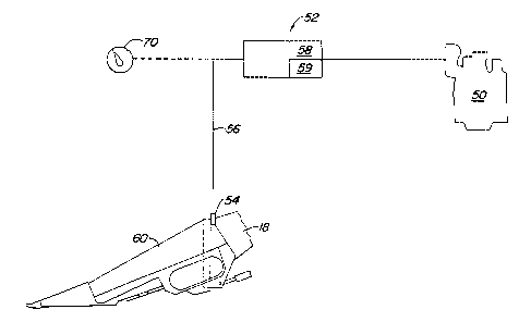
Figure 2 is a schematic of the operation of the present invention.
Detailed Description
Figure 1 shows an agricultural combine 10 comprising a supporting structure 12
having ground engaging wheels 14 extending from the supporting structure.
Although the
combine is illustrated as having wheels, it could also have ground engaging
tracks, either full
tracks or half tracks. Harvesting assemblies are detachably mounted to the
feederhouse 18.
These harvesting assemblies may comprise a variety of harvesting
configurations, including
a grain platform, a corn head, a row crop header or a pickup platform. In
Figure 1, a
harvesting assembly in the form of the illustrated grain platform 16 is used
for harvesting a
crop and directing it to a feederhouse 18. The feederhouse 18 contains a
conveyor for
conveying the harvested crop to a beater 20. The beater 20 directs the crop
upwardly
through an inlet transition section 22 to a rotary threshing and separating
assembly 24. The
illustrated threshing and separating assembly 24 is axially arranged in the
combine 10,
however, it could be in other orientations relative to the longitudinal axis
of the combine.
Although the present invention is described and illustrated as being used on a
rotary
threshing and separating assembly, it can also be used on a combine having a
conventional
transverse threshing cylinder and concave assembly.
The rotary threshing and separating assembly 24 threshes and separates the
harvested crop material. Grain and chaff fall through grates on the bottom of
the assembly
2

CA 02363210 2001-11-16
24 to a cleaning system 26. The cleaning system 26 removes the chaff and
directs the clean
grain to a clean grain elevator (not shown). The clean grain elevator deposits
the clean
grain in grain tank 28. The clean grain in the tank can be unloaded into a
grain cart or truck
by unloading auger 30.
Threshed and separated straw is discharged from the axial crop processing unit
through outlet 32 to discharge beater 34. The discharge beater in turn propels
the straw out
the rear of the combine. It should be noted that the discharge beater 34 could
also
discharge crop material other than grain directly to a straw chopper. The
operation of the
combine is controlled from operator's cab 35.
The rotary threshing and separating assembly 24 comprises a cylindrical rotor
housing 36 and a rotor 37 located inside the housing 36. The front part of the
rotor and the
rotor housing define the infeed section 38. Downstream from the infeed section
38 are the
threshing section 39, the separating section 40 and the discharge section 41.
The rotor 37
in the infeed section 38 is provided with a conical rotor drum having helical
infeed elements
for engaging harvested crop material received from the beater 20 and inlet
transition section
22. Immediately downstream from the infeed section 38 is the threshing section
39. In the
threshing section 39 the rotor 37 comprises a cylindrical rotor drum having a
number of
threshing elements for threshing the harvested crop material received from the
infeed
section 38. Downstream from the threshing section 39 is the separating section
40 wherein
the grain trapped in the threshed crop material is released and falls through
a floor grate in
the rotor housing 36 to the cleaning system 28. The separating section merges
into a
discharge section 41 where crop material other than grain is expelled from the
rotary
threshing and separating assembly 24.
As discussed above the various crop processing assemblies are powered by an
internal combustion engine 50, see Figure 2. This engine 50 is electronically
connected to
an electronic engine controller 52. In turn the electronic engine controller
is in
communication with a harvesting assembly detector 54 through line 56. The
harvesting
assembly in Figure 2 is a corn head 60 that is mounted to feederhouse 18. The
detector 54
provides a corn head signal to the controller 52 as a corn head is mounted to
the
feederhouse. For the harvesting assembly illustrated in Figure 1, the detector
54 provides a
grain platform signal to the controller 52 as a grain platform is mounted to
the feederhouse
18. The electronic engine controller stores at least two power curves in
memory. The first
power curve 58 has a higher horsepower output than the second power curve 59.
In
response to these harvesting assembly signals (corn head signal or grain
platform signal),
3

CA 02363210 2001-11-16
the controller 52 controls the engine based according to either the first
power curve or the
second power curve. If the harvesting assembly signal is a grain platform
signal, the
electronic controller 52 operates the engine 50 in accordance with the higher
horsepower
first power curve 58. If the harvesting assembly signal is a corn head signal,
the electronic
controller 52 operates the engine 50 in accordance with the second power curve
59.
The harvesting assembly detector 54 can comprise a number of configurations.
It
can be a simple two-position switch 70 located in the cab 35 and activated by
the operator.
It can be a switch located on the feederhouse, as illustrated in Figure 2,
that is activated
when one of the two harvesting assemblies is mounted to the feederhouse. In
addition, the
detection can be accomplished by the electronic hook up between the harvesting
assembly
and the combine. More specifically, modern combines have electronic monitoring
systems.
These monitoring systems use a CAN bus signaling methodology that can be used
to signal
the electronic engine controller.
The first power curve 58 and the second power curve 59 each may comprise a
family
of power curves. Other monitoring systems on the combine may dictate which of
the power
curves from the selected family would be used in a particular application or
configuration.
For example, when operating a grain platform a moisture sensor may be used to
monitor the
moisture content of the harvested crop. The moisture signal of the moisture
sensor may
dictate a specific power curve from the grain platform family of power curves.
The opposite
may also be true where the harvesting assembly configuration is used to select
a specific
power curve from a family of power curves.
The present invention should not be limited by the above described embodiment,
but
should be limited solely by the claims that follow.
4

Representative Drawing
A single figure which represents the drawing illustrating the invention.
Administrative Status

2024-08-01:As part of the Next Generation Patents (NGP) transition, the Canadian Patents Database (CPD) now contains a more detailed Event History, which replicates the Event Log of our new back-office solution.

Please note that "Inactive:" events refers to events no longer in use in our new back-office solution.

For a clearer understanding of the status of the application/patent presented on this page, the site Disclaimer , as well as the definitions for Patent , Event History , Maintenance Fee  and Payment History  should be consulted.

Event History

Description Date
Time Limit for Reversal Expired 2007-11-16
Letter Sent 2006-11-16
Inactive: IPC from MCD 2006-03-12
Grant by Issuance 2004-07-13
Inactive: Cover page published 2004-07-12
Inactive: Final fee received 2004-04-30
Pre-grant 2004-04-30
Notice of Allowance is Issued 2003-11-03
Letter Sent 2003-11-03
Notice of Allowance is Issued 2003-11-03
Inactive: Approved for allowance (AFA) 2003-10-21
Amendment Received - Voluntary Amendment 2003-03-19
Application Published (Open to Public Inspection) 2002-08-14
Inactive: Cover page published 2002-08-13
Inactive: IPC assigned 2002-01-21
Inactive: First IPC assigned 2002-01-21
Letter Sent 2001-12-21
Filing Requirements Determined Compliant 2001-12-21
Inactive: Filing certificate - RFE (English) 2001-12-21
Letter Sent 2001-12-18
Application Received - Regular National 2001-12-18
Request for Examination Requirements Determined Compliant 2001-11-16
All Requirements for Examination Determined Compliant 2001-11-16

Abandonment History

There is no abandonment history.

Maintenance Fee

The last payment was received on 2003-11-14

Note : If the full payment has not been received on or before the date indicated, a further fee may be required which may be one of the following

  • the reinstatement fee;
  • the late payment fee; or
  • additional fee to reverse deemed expiry.

Please refer to the CIPO Patent Fees web page to see all current fee amounts.

Fee History

Fee Type Anniversary Year Due Date Paid Date
Registration of a document 2001-11-16
Application fee - standard 2001-11-16
Request for examination - standard 2001-11-16
MF (application, 2nd anniv.) - standard 02 2003-11-17 2003-11-14
Final fee - standard 2004-04-30
MF (patent, 3rd anniv.) - standard 2004-11-16 2004-11-04
MF (patent, 4th anniv.) - standard 2005-11-16 2005-11-02
Owners on Record

Note: Records showing the ownership history in alphabetical order.

Current Owners on Record
DEERE & COMPANY
Past Owners on Record
KEVIN LAVERNE EHRECKE
Past Owners that do not appear in the "Owners on Record" listing will appear in other documentation within the application.
Documents

To view selected files, please enter reCAPTCHA code :


To view images, click a link in the Document Description column. To download the documents, select one or more checkboxes in the first column and then click the "Download Selected in PDF format (Zip Archive)" or the "Download Selected as Single PDF" button.

List of published and non-published patent-specific documents on the CPD .

If you have any difficulty accessing content, you can call the Client Service Centre at 1-866-997-1936 or send them an e-mail at CIPO Client Service Centre.


Document
Description 
Date
(yyyy-mm-dd) 
Number of pages   Size of Image (KB) 
Representative drawing 2002-02-14 1 5
Abstract 2001-11-16 1 21
Description 2001-11-16 4 218
Claims 2001-11-16 2 82
Drawings 2001-11-16 2 43
Cover Page 2002-08-09 1 37
Cover Page 2004-06-10 1 38
Acknowledgement of Request for Examination 2001-12-18 1 179
Courtesy - Certificate of registration (related document(s)) 2001-12-21 1 113
Filing Certificate (English) 2001-12-21 1 164
Reminder of maintenance fee due 2003-07-17 1 106
Commissioner's Notice - Application Found Allowable 2003-11-03 1 159
Maintenance Fee Notice 2007-01-04 1 171
Correspondence 2004-04-30 1 23