Note: Descriptions are shown in the official language in which they were submitted.
CA 02363408 2001-11-15
LASER SHOCK PEENING QUALITY ASSURANCE
BY ULTRASONIC ANALYSIS
BACKGROUND OF THE INVENTION
FIELD OF THE INVENTION
This invention relates to quality assurance methods used for quality assurance
for laser shock peening and, more particularly, for ultrasonic testing and
statistical
analysis of laser shock peened surfaces for quality assurance of a production
laser
shock peening process.
DISCUSSION OF THE BACKGROUND ART
Laser shock peening or laser shock processing, as it is also referred to, is a
process for producing a region of deep compressive residual stresses imparted
by
laser shock peening a surface area of a workpiece. Laser shock peening
typically uses
multiple radiation pulses from high power pulsed lasers to produce shock waves
on
the surface of a workpiece similar to methods disclosed in U.S. Patent No.
3,850,698,
entitled "Altering Material Properties"; U,S. Patent No. 4,401,477, entitled
"Laser
Shock Processing"; and U.S. Patent No. 5,131,957, entitled "Material
Properties".
Laser shock peening, as understood in the art and as used herein, means
utilizing a
laser beam from a laser beam source to produce a strong localized compressive
force
on a portion of a surface by producing an expiosive force by instantaneous
ablation or
vaporization of a painted or coated or uncoated surface. Laser peening has
been
utilized to create a compressively stressed protection layer at the outer
surface of a
workpiece which is known to considerably increase the resistance of the
workpiece to
fatigue failure as disclosed in U.S. Patent No. 4,937,421, entitled "Laser
Peening
System and Method". These methods typically employ a curtain of water flowed
over
the workpiece or some other method to provide a confining medium to confine
and
redirect the process generated shock waves into the bulk of the material of a
component being LSP'D to create the beneficial compressive residual stresses.
CA 02363408 2001-11-15
Laser shock peening is being developed for many applications in the gas
turbine engine field, some of which are disclosed in the following U.S. Patent
Nos.:
5,756,965 entitled "ON THE FLY LASER SHOCK PEENING"; 5,591,009, entitled
"Laser shock peened gas turbine engine fan blade edges"; 5,569,018, entitled
"Technique to prevent or divert cracks"; 5,531,570, entitled "Distortion
control for
laser shock peened gas turbine engine compressor blade edges"; 5,492,447,
entitled
"Laser shock peened rotor components for turbomachinery"; 5,674,329, entitled
"Adhesive tape covered laser shock peening"; and 5,674,328, entitled "Dry tape
covered laser shock peening", all of which are assigned to the present
Assignee.
These applications, as well as others, are in need of efficient quality
assurance testing
during production runs using laser shock peening.
LSP is a deep treatment of the material and it is desirable to have a quality
assurance test that is indicative of a volumetric LSP effect. It is also
desirable to have
a QA method that is compatible with a dual sided or simultaneous dual sided
LSP
process wherein substantially equal compressive residual stresses are imparted
to both
sides of a workpiece, i.e. along the leading edge of a gas turbine engine fan
blade.
One laser shock peening quality assurance technique previously used is high
cycle fatigue (HCF) testing of blades having leading edges which are LSP'd and
notched in the LSP'd area before testing. This method is destructive of the
test piece,
fairly expensive and time consuming to carry out, and significantly slows
production
and the process of qualifying LSP'd components. An improved quality assurance
niethod of measurement and control of LSP that is a non-destructive evaluation
(NDE), inexpensive, accurate, and quick is highly desirable. It is also
desirable to
have an NDE quality assurance method that is relatively inexpensive and
sufficiently
economical to be used on each workpiece instead of a sampling of workpieces.
LSP
is a process that, as any production technique, involves machinery and is time
consuming and expensive. Therefore, any techniques that can reduce the amount
or
complexity of production machinery and/or production time are highly
desirable.
Interferometric profilometry method and apparatus to obtain volumetric data
of a single laser shock peened test dimple created with a single firing of a
laser used
2
CA 02363408 2001-11-15
in the laser shock peening process is disclosed in U.S. Patent No. 5,948,293
"Laser
shock peening quality assurance by volumetric analysis of laser shock peened
dimple". Other QA methods are disclosed in U.S. Patent No. 5,987,991
"Determination of Rayleigh wave critical angle"; U.S. Patent No. 5,974,889
"Ultrasonic multi-transducer rotatable scanning apparatus and method of use
thereof";
and U.S. Patent No. 5,951,790 "Method of monitoring and controlling laser
shock
peening using an in plane deflection test coupon".
SUMMARY OF THE INVENTION
A method for quality control testing of a laser shock peening process of a
production workpiece includes (a) ultrasonically scanning at least a portion
of a laser
shock peened surface on the workpiece wherein a region having deep compressive
residual stresses imparted by the laser shock peening process extends into the
workpiece from the laser shock peened surface, (b) digitizing a signal derived
from
the scanning and forming a digitized image of intensity values from the
scanning, (c)
calculating at least one statistical function value for a plurality of points
of the
digitized image of the workpiece based on the intensity values, and (d)
comparing the
statistical function value to a pass or fail criteria for quality assurance of
the laser
shock peening process or accepting or rejecting the workpiece.
In one exemplary embodiment of the invention the plurality of points of the
~o digitized image (44) are delineated by a group of circles corresponding to
laser shock
peened dimples within the portion of the laser shock peened surface. The
statistical
function comprises at least one of four statistical properties of the
digitized image
defined by four equations, a Mean Nfatrix MM(k) for each kth dimple, a Dimple
Standard Deviation Matrix SDM(k), a Mean Vector MV(x) of all the points in the
group of circles, where x is the number of pixels in each dimple, and a
Standard
Deviation Vector SDV(x) of each of the group of circles. Three types of the
statistical function are a Mean of Dimple Mean Matrix Fl, a Mean of Standard
Deviation Matrix F2, and a Mean of Standard Deviation Vector F3.
3
CA 02363408 2001-11-15
In another exemplary embodiment of the invention the plurality of points of
the digitized image are delineated by a rectangle around laser shock peened
dimples
w=ithin a portion of the laser shock peened surface and the statistical
function is a
Sobel Function F4 including a Sobel operator.
The pass or fail criteria is based on a pre-determined correlation of test
piece
statistical function data and high cycle fatigue failure based on high cycle
fatigue tests
of test pieces that were laser shock peened in the same or similar laser shock
peening
apparatus. Each of the test pieces has a failure precipitating flaw within a
laser shock
peened area of the test piece that was laser shock peened in the same or
similar laser
shock peening apparatus.
BRIEF DESCRIPTION OF THE DRAWINGS
The foregoing aspects and other features of the invention are explained in the
following description, taken in connect;on with the accompanying drawings
where:
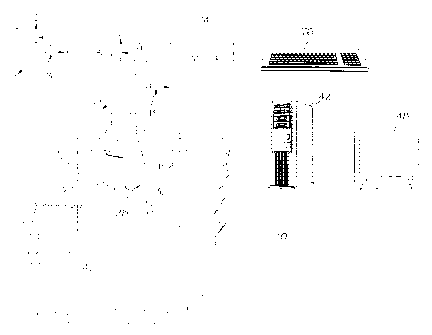
FIG. I is a diagrammatic illustration of an ultrasonic system set up for
ultrasonically scanning and producing an ultrasonic intensity image of a
portion of a
laser shock peened patch of a fan blade for use in an exemplary embodiment of
the
method of the present invention.
FIG. 2 is a perspective view illustration of a production fan blade
exemplifying a laser shock peened production workpiece used in an exemplary
enibodiment of the present invention.
FIG. 3 is a cross-sectional view illustration of the fan blade through 3-3 in
FIG. 2.
FIG. 4 is an illustration of a computer screen depicting ultrasonic intensity
data from a scan of a laser shock peened patch in FIG. 2 and virtual circles
delineating data used in some of the embodiments of the present invention.
FIG. 5 is an illustration of points in one of the virtual circles of the
intensity
data in FIG. 4 that are used to compute some of statistical functions.
4
CA 02363408 2004-08-12
13DV13161
FIG. 6 is an illustration of the computer screen in FIG. 4 with a virtual
rectangle surrounding a set ultrasonic intensity data used in with a Sobel
operator
statistical function.
FIG. 7 is an illustration of points in the virtual rectangle the intensity
data in
FIG. 6 that is used with a Sobel operator statistical function.
FIG. 8 is an illustration of a four statistical properties used to analyze the
intensity data of the points in FIG. 4.
FIG. 9 is an illustration of four exemplary statistical function used to
analyze
the intensity data of the points in FIGS. 4 and 6.
FIG. 10 is an illustration of the Sobel operator used in the Sobel statistical
function F4 in FIG. 9.
FIG. 11 is a perspective view of a test fan blade exemplifying a test piece
which is used to determine a correlation between high cycle fatigue failure
and the
exemplary statistical functions.
FIG. 12 is a schematic perspective illustration of the blade in FIGS. 1 and 2
mounted in a laser shock peening system.
DETAILED DESCRIPTION
Quality assurance is typically a go or no go, pass or fail, accept or reject
type
of analysis. The method and techniques of the present invention involves
quality
assurance of the laser shock peening process on a production workpiece such as
an
exemplary aircraft turbofan gas turbine engine production fan blade 108
illustrated in
FIGS. 1, 2, and 3. Illustrated in FIG. 1 is a diagrammatic representation of
an
ultrasonic scanning system 10 used to perform a quality assurance method for
quality
control of a laser shock peening process. The method and techniques of the
present
invention involves quality assurance of a laser shock peening process on a
production
workpiece such as an exemplary aircraft turbofan gas turbine engine fan blade
108 or
other object made of a metallic material as disclosed in U.S. Patent Nos.
5,492,447,
5,674,329, 5,674,328, and 5,591,009. The methods of the present invention are
tests
performed during or after laser shock peening of each workpiece, or after or
before a
CA 02363408 2001-11-15
1 J L Y 1 J 1 V 1
batch of workpieces are laser shock peened. During production runs, one or
more
functions of ultrasonic intensity data is compared to pre-determined pass/fail
criteria
such as a high cycle fatigue correlation for passing or failing the
workpieces.
Referring to FIGS. 2 and 3, the production fan blade 108 includes an airfoil
134 extending radially outward from a blade platform 136 to a blade tip 138
and a
root section 140 extending radially inward from the platform 136. The root
section
140 has a blade root 142 connected to the platform 136 by a blade shank 144.
The
airfoil 134 extends in a chordwise direction between a leading edge LE and a
trailing
edge TE of the airfoil. The fan blade 108 has a leading edge section 150 that
extends
to along the leading edge LE of the airfoil 134 from the blade platform 136 to
the blade
tip 138. The airfoil 134 has a pressure side 146 and a suction side 148
extending
between the leading edge and trailing edges LE and TE of the airfoil. The
leading
edge section 150 includes a pre-determined first width W such that the leading
edge
section 150 encompasses an area where nicks and tears that may occur along the
leading edge of the airfoil 134 during engine operation. The airfoil 134
subject to a
significant tensile stress field due to centrifugal forces generated by the
fan blade 108
rotating during engine operation. The airfoil 134 is also subject to
vibrations
generated during engine operation and the nicks and tears operate as high
cycle
fatigue stress risers producing additional stress concentrations around them.
To counter fatigue failure of portions of the blade along possible crack lines
that can develop and emanate from the nicks and tears, a laser shock peened
patch
145 is placed along a portion of the leading edge LE where incipient nicks and
tears
may cause a failure of the blade due to high cycle fatigue. Within the laser
shock
peened patch 145, at least one of or both, as illustrated herein, the pressure
side 146
and the suction side 148 are simultaneously laser shock peened to form
pressure side
and suction side laser shock peened surfaces 153 and 154 and corresponding
pressure
side and suction side pre-stressed regions 155 and 156, respectively, having
deep
compressive residual stresses imparted by laser shock peening (LSP) extending
into
the airfoil 134 from the laser shock peened surfaces as seen in FIG. 2. The
pre-
stressed regions are illustrated along only a portion of the leading edge
section 150
6
CA 02363408 2001-11-15
L J LJ = l J 1 V 1
but may extend along the entire leading edge LE or longer portion thereof if
so
desired.
The pre-determined criteria of the exemplary embodiment is based on a
correlation of one or more functions of ultrasonic intensity data versus high
cycle
fatigue data of test versions of the workpieces that are exemplified by laser
shock
peened and notched test fan blades 109 illustrated in FIG. 11. The production
and test
blades fan 108 and 109, respectively, are laser shock peened the same way
during
production runs and HCF testing runs for the correlation.
Illustrated in FIG. I is a schematic representation of an ultrasonic scanning
system 10 used to perform a quality assurance method for quality control of a
laser
shock peening process. The system 10 is used for production and test
workpieces
exemplified by the production fan blade 108 having a laser shock peened patch
145
illustrated in greater detail in FIG. 2. The method includes ultrasonically
scanning at
least a portion of the patch 145, measuring an ultrasonic signal, digitizing
the
ultrasonic signal and recording the digitized ultrasonic intensity data,
calculating at
least one statistical function of digitized ultrasonic intensity data derived
from the
intensity ultrasonic signal, and comparing the statistical function or
functions to a
high cycle fatigue correlation of the same type of statistical function or
functions to
decide whether the laser shocking process or laser shock peened article is
acceptable.
10 An exemplary embodiment of the invention illustrated in FIG. 1 uses
ultrasonic scanning and the ultrasonic scanning system 10 includes an
ultrasonic
transmitting transducer 30 to pass the ultrasonic beam 28 through the fan
blade 108
~vithin the bounds of the laser shock peened patch 145 to an ultrasonic
receiving
transducer 32. The fan blade 108 is mounted on a carrier 70 and a portion of
the
blade with the laser shock peened patch 145 is submerged in an ultrasonic
medium 40
such as water. The carrier 70 is operated to move the fan blade 108 such that
the
ultrasonic beam 28 from the ultrasonic transmitting transducer 30 passes
through the
laser shock peened patch 145 to an ultrasonic receiving transducer 32 while a
computer 42 or other recording device records electronic signals from the
receiving
transducer as a function of material density and morphology of the dimples
caused by
7
CA 02363408 2004-08-12
13DV13161
the laser shock peening impact on the patch. The carrier 70 has a multi axis
motive
means for translating the fan blade 108 in the X, Y and Z directions as well
as rotating
the fan blade about A and B axes as indicated to position the blade relative
to the
fixed ultrasonic beam 28, and ultrasonic transmitting transducer and
ultrasonic
receiving transducers 30 and 32. The movement of the carrier 70 may be
controlled
by a controller 74 with the use of a keyboard 76 operated by a user.
The recorded electronic signals are converted into an ultrasonic intensity
image 44 that is stored in a computer 42 and can be displayed on a screen 48
of the
computer 42 as illustrated in FIG. 4. The invention in its broader aspects can
use
different types of emissions which are processed with the computer and
recorded in a
computerized array of values or in the digitized ultrasonic intensity image 44
as a
plurality of pixels 46 illustrated in FIG. 4 which is then analyzed with
statistical
functions.
The exemplary embodiment illustrated herein uses pixel data derived from
recorded intensity data from the scanning of the patch 145 with the ultrasonic
beam
20. Illustrated in FIG. 4 is a digital image depicting ultrasonic intensity
data in pixel
format from a scan of the laser shock peened patch 145 in FIGS. 1 and 2. Eight
virtual circles 80 surrounding a portion of the plurality of pixels 46 are
chosen to
delineate the pixel data used in one embodiment of the statistical analysis of
the
present invention. Each of the virtual circles 80 corresponds to one of the
laser shock
peened circular dimples 158. If the dimples are not circular then other
virtual shapes
may be used as alternatives to the virtual circles. More or less than eight
virtual
shapes or circles may be used.
FIG. 5 is an illustration of an array 112 of points 114 in the virtual circle
80
that are used to analyze the intensity data from FIG. 4 and to compute
statistical
functions from the intensity data illustrated in FIG. 4. The results of the
computed
statistical functions from the intensity data are compared to a high cycle
fatigue
correlation of the same type of statistical function or functions to decide
whether the
laser shocking process or laser shock peened article is acceptable.
8
CA 02363408 2001-11-15
The statistical functions exemplified herein use four statistical properties
of
the digitized ultrasonic intensity images 44. Equations in FIG. 8 define these
statistical properties as follows: a Mean Matrix MM(k) for each kth dimple
(illustrated for K=8 dimples per blade); a Dimple Standard Deviation Matrix
SDM(k);
a Mean Vector MV(x) for each xth pixel in each dimple and where X is the total
number of points or pixels in each dimple (illustrated as 377 pixels); and a
Standard
Deviation Vector SDV(x).
Equations in FIG. 9 define four alternative statistical functions (F1-F4) each
of
which is suitable for use in the analysis of the present invention. Each of
the
-o statistical functions (F1-F4) is calculated for each workpiece or blade.
The first
statistical function is a Mean of Dimple Mean Matrix Fi, and is computed using
one
or more rows of the dimples up to and including all the dimples. The exemplary
embodiment used herein uses four of the dimples per row and 2 of the rows of
dimples are per blade. Thus, there are 8 dimples per blade and 377 pixel
points
within each of the dimples and, therefore, the function is summed over k=1-8
and
r=1-377. A measured variable is dk(x) is a pixel intensity within kth dimple.
First,
377 pixel intensity values dk(x) for each dimple (x) is summed and the
resulting eight
dimple sums are summed resulting in a total sum. The Mean of Dimple Mean
Matrix
F I is then computed for each blade by dividing total sum by K which is the
number of
'0 dimples (x).
The second statistical function is a Mean of Standard Deviation Matrix F2 and
is computed using one or more rows of the dimples up to and including all the
dimples. The exemplary embodiment used herein uses four of the dimples per row
and 2 of the rows of dimples are per blade. Again illustrated herein is four
dimples
per row and 2 rows are per blade and each dimple having 377 pixel points. A
Standard Deviation (SD) for 377 pixels is calculated for each of the K dimples
then
the K SDs are summed and that sum is divided by the total number of dimples K.
The third statistical function is a Mean of Standard Deviation Vector F3 and
is
computed using one or more rows of the dimples up to and including all the
dimples.
The exemplary embodiment used herein uses four of the dimples per row and 2 of
the
9
CA 02363408 2004-08-12
13DV13161
rows of dimples are per blade. It assumes that four dimples per row and 2 rows
are
per blade'which are 8 dimples. Each dimple has 377 pixel points. First, a
Standard
Deviation Vector (SDV) for the 8 dimples is calculated for each of the 377
pixels then
the 377 SDVs are summed and that sum is divided by 377 which is the total
number
of points.
Illustrated in FIG. 6 is the digital image depicting the ultrasonic intensity
data
in pixel format from a scan of the laser shock peened patch 145 in FIGS. I and
2, a
portion of the plurality of pixels 46, the virtual circles 80 bounded by a
virtual
rectangle 84. The virtual rectangle 84 is used to delineate pixel data used
with a
fourth statistical function, a Sobel function F4 illustrated in FIG. 9. The
exemplary
embodiment as illustrated herein uses a virtual rectangle 84 that encompasses
three of
the dimples per row and three of the rows of dimples are per blade. In the
equation of
the Sobel Function F4, i and j are x and y directional points within the
rectangle 84 in
FIG. 3. An exemplary area of the rectangle shown in FIG. 6 or FIG. 7 is 2
inches by
1/2 inch. The rectangle 84 is two inches long in the x direction and 1/2 inch
long in
the y direction. Pixels intensities in the rectangle were broken up into
250X50 points
such that i=1-250 and j=1-50.
The function du,v= pixel value at the nine points u,v for each point ij and
the
function wu,v= the Sobel operator at u,v which is illustrated in FIG. 10. In
the
exemplary embodiment used herein, a 3x3 Sobel operator W, the variables u,v
are
positions in an array that includes the point ij and the 8 surrounding points
in the
array of pixels in the image such that u= 1 to 3 and v = 1 to 3. A scaling
factor N
(10,000 was used in the exemplary embodiment) is used to make F4 a low number
that is easy to work with. Sobel operators are well known for use in edge
detection
and image enhancement techniques using pixel intensity data. The Sobel
operator
used herein is a 3 x 3 non-linear edge enhancement.
The Sobel operator W, as illustrated in FIG. 10, is in the form of a three by
three operator array that multiplies a specific pixel intensity D by zero
which is the
center number in the array as designated by numeral 51. It then multiplies all
surrounding pixels intensities by a-1, -2, -1, 0, 1, 2, 1, and 0 respectively
from left to
CA 02363408 2004-08-12
13DV13161
right in a clockwise fashion, as shown in FIG. 10. The summation of all of
these
multiplied values is the new replacement value for this specific pixel
intensity of
interest. If there are no spatial discontinuities from top to bottom, then the
pixels
above, the pixel of interest, will be multiplied by a negative number that is
equivalent
to the multipliers below the pixel of interest. Therefore, if the pixel
numbers are
relatively the same, the summation will be close to zero.
The high cycle fatigue (HCF) correlation of the test fan blades 109
illustrated
herein is based on fatigue testing of laser shock peened and notched test fan
blades
109 as illustrated in FIG. 11, that are full scale and notched to precipitate
a failure.
The test pieces or test fan blades 109 are made the same way as the actual
production
fan blades 108 with a notch 152 added after the test blade 109 is laser shock
peened to
form the patch 145.
The laser shock peened test fan blades 109 are ultrasonically scanned and the
digitized ultrasonic intensity data stored for statistical analysis. The HCF
testing may
be used to establish pass/fail criteria for use during production runs to be
compared to
the results of the statistical analysis from ultrasonic scanning and
statistical analysis
of the digitized ultrasonic intensity data from the scanning. The digitized
ultrasonic
intensity data is recorded and analyzed for correlation purposes. The laser
shock
peened test fan blades 109 are vibrated at its first mode frequency until it
fails. A
number of test fan blades 109 or just one test blade 109 may be notched and
subjected
to high cycle fatigue tests to establish the correlation. For high cycle
fatigue, each
laser shock peened test fan blade 109 has a notch 152, representing a failure
precipitating flaw, placed in the laser shock peened patch 145. The notch 52
is placed
at a pre-determined position of the pre-stressed regions 155 and 156 after the
blade is
laser shock peened. The notch 152 may be centered about a predetermined mode
line
such as a first mode line LM. If tested blade meets standards or test criteria
on length
of time and amplitude of the forcing function that is exiting the blade, then
it is
acceptable. These results can then be used during production runs to qualify
the laser
shock peening process. It is contemplated that one calibration can be used for
an
11
CA 02363408 2001-11-15
LJL! ~ LJLVL
entire production run as long as the production laser shock peening parameters
do not
change.
Illustrated in FIG. 12 is a laser shock peening apparatus and system 101 for
laser shock peening the fan blade 108. The fan blade 108 is mounted in the
fixture 15
which is attached to a five-axis computer numerically controlled (CNC)
manipulator
127. Five axes of motion illustrated in the exemplary embodiment are
conventional
translational axes X, Y, and Z, and converitional rotational axes A and C
which are
well known in CNC machining. The manipulator 127 moves and positions the
production and test production fan blades 108 and 109 to effect laser shock
peening
to on the fly. Laser shock peening may be done in a number of various ways
using paint
or tape as an ablative medium (see U.S. Patent No. 5,674,329 entitled
"Adhesive Tape
Covered Laser Shock Peening"). The same laser shock peening apparatus and
system
101 is used in the laser shock peening process of the leading edge section 150
of the
production fan blade 108 and the test fan blades 109 (representing the test
pieces and
workpieces).
The area to be laser shock peened and form the laser shock peened patch 145,
the pressure and suction side laser shock peened surfaces 153 and 154 are
covered
with an ablative coating such as paint or adhesive tape to form a coated
surface as
disclosed in U.S. Patent Nos. 5,674,329 and 5,674,328. The coating provides an
ablative medium over which is a clear containment medium which may be a clear
tluid curtain such as a curtain of flowing water 121.
The laser beam shock induced deep compressive residual stresses may be
produced by repetitively firing two high power laser beams 102, each of which
is
defocused a few mils with respect to the coated pressure side and suction
side laser
shock peened surfaces 153 and 154 of the pressure side 146 and the suction
side 148
of the production fan blade 108. Each of the laser beams is fired through the
curtain
of flowing water 121 supplied by a conventional water nozzle 123 at the end of
a
conventional water supply tube 119. The curtain of flowing water 121 is flowed
over
the coated surfaces. The coating is ablated generating plasma which results in
shock
waves on the surface of the material. Other ablative materials may be used to
coat the
12
CA 02363408 2001-11-15
1JL/ = 1J 1V t
surface as suitable alternatives to paint. These coating materials include
metallic foil
or adhesive plastic tape as disclosed in U.S. Patent Nos. 5,674,329 and
5,674,328.
These shock waves are re-directed towards the coated surfaces by the curtain
of
flowing water 121 to generate travelling shock waves (pressure waves) in the
material
below the coated surfaces. The amplitude and quantity of these shock waves
determine the depth and intensity of compressive stresses. The ablative
coating is
used to protect the target surface and also to generate plasma. The ablative
coating is
used to protect the target surface and also to generate plasma. The laser beam
shock
induced deep compressive residual stresses in the compressive pre-stressed
regions
are generally about 50-150 KPSI (Kilo Pounds per Square Inch) extending from
the
laser shock peened surfaces to a depth of about 20-50 mils into the pre-
stressed
regions.
The production fan blade 108 is continuously moved while the stationary high
power laser beams 102 are continuously firing through the curtain of flowing
water
121 ori the coated pressure and suction side laser shock peened surfaces 153
and 154
and forming spaced apart laser shock peened circular spots or dimples 158. The
production fan blades 108 are laser shock peened the same way during
production
runs and HCF testing runs for the correlation. A controller 124 is used to
modulate
and control the laser shock peening system 101 to fire the laser beams 102 on
the
coated surfaces in a controlled manner. Ablated coating material is washed out
by the
curtain of flowing water 121.
The embodiment of the method of the present invention illustrated herein
includes continuously moving the blade while continuously firing the laser
beam on
the taped surface and adjacent laser shock peened circular spots may be hit in
different sequences. However, the laser beam may be moved instead just so long
as
relative movement between the beam and the surface is effected.
While there have been described herein what are considered to be preferred
and exemplary embodiments of the present invention, other modifications of the
invention shall be apparent to those skilled in the art from the teachings
herein and, it
is therefore, desired to be secured in the appended claims all such
modifications as
13
CA 02363408 2001-11-15
fall within the true spirit and scope of the invention. Accordingly, what is
desired to
be secured by Letters Patent of the United States is the invention as defined
and
differentiated in the following claims:
14