Language selection

Search

Patent 2363616 Summary

Third-party information liability

Some of the information on this Web page has been provided by external sources. The Government of Canada is not responsible for the accuracy, reliability or currency of the information supplied by external sources. Users wishing to rely upon this information should consult directly with the source of the information. Content provided by external sources is not subject to official languages, privacy and accessibility requirements.

Claims and Abstract availability

Any discrepancies in the text and image of the Claims and Abstract are due to differing posting times. Text of the Claims and Abstract are posted:

  • At the time the application is open to public inspection;
  • At the time of issue of the patent (grant).
(12) Patent Application: (11) CA 2363616
(54) English Title: FLUID ACTUATOR FOR HINGED VEHICLE SAFETY DEVICES
(54) French Title: ACTIONNEUR HYDRAULIQUE POUR DISPOSITIFS DE SECURITE ARTICULES DE VEHICULES
Status: Deemed Abandoned and Beyond the Period of Reinstatement - Pending Response to Notice of Disregarded Communication
Bibliographic Data
(51) International Patent Classification (IPC):
  • F15B 15/08 (2006.01)
  • B60Q 1/50 (2006.01)
  • B60R 99/00 (2009.01)
  • F16J 1/10 (2006.01)
  • G09F 7/18 (2006.01)
  • G09F 7/22 (2006.01)
  • G09F 21/04 (2006.01)
(72) Inventors :
  • LAMPARTER, RONALD C. (United States of America)
  • HAIGH, JAMES A. (United States of America)
  • IMINSKI, RICHARD J. (United States of America)
(73) Owners :
  • TRANSPEC, INC.
(71) Applicants :
  • TRANSPEC, INC. (United States of America)
(74) Agent: SMART & BIGGAR LP
(74) Associate agent:
(45) Issued:
(22) Filed Date: 2001-11-22
(41) Open to Public Inspection: 2002-09-02
Availability of licence: N/A
Dedicated to the Public: N/A
(25) Language of filing: English

Patent Cooperation Treaty (PCT): No

(30) Application Priority Data:
Application No. Country/Territory Date
09/798,149 (United States of America) 2001-03-02

Abstracts

English Abstract


A fluid actuator attaches a hinged safety device to a vehicle and pivots the
hinged
safety device between retracted and extended positions. The housing of the
actuator has
a base and a removable cover. A sub-assembly is attached to the base. The
subassembly
includes a generally planar base member with integral right cylinder, lever
arm pivot
support and stop posts. A piston slides in the right cylinder and forms a
fluid chamber
between the piston and a closed end of the right cylinder that is fed through
a passage
through the closed end of the cylinder. A lever arm is pivotally attached to
the lever arm
pivot support at one end for pivotal movement between retracted and extended
positions,
the lever arm extending over the cylinder and having a lip at an opposite end
that is
spaced from the right cylinder. A pivot arm engages the top of the piston at
one end and
the lever arm at an opposite end to transfer motion from the piston to the
lever arm. The
lever arm transfers motion to a rotor that is rotationally mounted in the
housing for
movement between retracted and extended positions. The rotor has a spool at
each end
and an eccentric arm between the spools at the respective ends of the rotor
that engages
the lip of the lever arm. A torsion spring encircles each spool with one end
engaging the
rotor and an opposite end engaging a stop post so that the eccentric arm is
biased against
the lip of the lever arm and the rotor and the lever arm are biased to their
respective
retracted positions.


Claims

Note: Claims are shown in the official language in which they were submitted.

8
I Claim:
1. A fluid actuator for attaching a hinged safety device to a vehicle and
pivoting
the hinged safety device between retracted and extended positions comprising:
a housing having a right cylinder attached to the housing inside the housing,
the
right cylinder having a closed end and an open end,
a piston that slides in the right cylinder and forms a fluid chamber between
the
piston and the closed end of the right cylinder,
a passage that extends into the housing and opens into the fluid chamber,
a lever arm pivot support inside the housing that defines a pivot axis,
a lever arm pivotally attached to the lever arm pivot support at one end for
pivotal
movement about the pivot axis between retracted and extended positions, the
lever arm
extending over the cylinder and having a lip at an opposite end that is spaced
from the
right cylinder,
a pivot arm that engages an upper surface of the piston at one end and that
engages the lever arm at an opposite end,
a rotor that is rotationally mounted in the housing for movement between
retracted and extended positions, the rotor having a spool at one end and an
eccentric arm
engaging the lip of the lever arm, and
a torsion spring encircling the spool with one end engaging the rotor and an
opposite end engaging a stop in the housing so that the eccentric arm is
biased against
the lip of the lever arm, and the rotor and the lever arm are biased to their
respective
retracted positions.

9
2. The fluid actuator as defined in claim 1 wherein the piston has a cavity in
an
upper surface that includes a concentric ball socket, and the pivot arm has a
ball at the
one end that engages the ball socket.
3. The fluid actuator as defined in claim 2 wherein the lever arm has a seat
between the one end and the opposite end of the lever arm, and the pivot arm
has a nose
at the opposite end that engages the seat of the lever arm.

10
4. A fluid actuator for attaching a hinged safety device to a vehicle and
pivoting
the hinged safety device between retracted and extended positions comprising:
a housing having a base and a cover,
a right cylinder attached to the base, the right cylinder having a closed end
and an
open end that faces the cover,
a piston that slides in the right cylinder and forms a fluid chamber between
the
piston and the closed end of the right cylinder, the piston having a cavity in
an upper
surface that includes a concentric ball socket,
the base having a passage extending through it and opening into the fluid
chamber,
a lever arm pivot support that is attached to the base and that defines a
pivot axis,
a lever arm pivotally attached to the lever arm pivot support at one end for
pivotal
movement about the pivot axis between retracted and extended positions, the
lever arm
extending over the cylinder and having a lip at an opposite end that is spaced
from the
right cylinder, the lever arm having a seat near a centerline of the cylinder,
a pivot arm that has a ball at one end that engages the ball socket of the
piston
and a cylindrical nose at an opposite end that engages the seat of the lever
arm,
a rotor that is rotationally mounted in the housing for movement between
retracted and extended positions, the rotor having a spool at each end and an
eccentric
arm between the spools at the respective ends of the rotor, the eccentric arm
engaging
the lip of the lever arm, and
a torsion spring encircling each spool with one end engaging the rotor and an
opposite end engaging a stop that is attached to the base so that the
eccentric arm is
biased against the lip of the lever arm and the rotor and the lever arm are
biased to their
respective retracted positions.

11
5. The fluid actuator as defined in claim 4 wherein the eccentric arm of the
rotor
is spaced from the cover when the rotor is in the extended position to permit
over travel
of the rotor.

12
6. A fluid actuator for attaching a hinged safety device to a vehicle and
pivoting
the hinged safety device between retracted and extended positions comprising:
a housing having a base and a removable cover,
a generally planar base member disposed in the housing,
a right cylinder attached to the base member, the right cylinder having a
closed
end at the base member and an open end spaced from the base member,
a piston that slides in the right cylinder and forms a fluid chamber between
the
piston and the closed end of the right cylinder, the piston having a cavity in
an upper
surface that includes a concentric ball socket,
the base member having a passage extending through it and opening into the
fluid
chamber,
a lever arm pivot support that is attached to the base member and that defines
a
pivot axis substantially parallel to the generally planar base member, the
lever arm
pivot support comprising laterally spaced supports and a retainer disposed
between the
laterally spaced supports,
a lever arm pivotally attached to the lever arm pivot support at one end for
pivotal
movement between retracted and extended positions, the lever arm extending
over the
cylinder and having a lip at an opposite end that is spaced from the right
cylinder, the
lever arm having a semi-cylindrical seat near a centerline of the cylinder,
a pivot arm that has a ball at one end that engages the ball socket of the
piston
and a cylindrical nose at an opposite end that engages the seat of the lever
arm,
a rotor that is rotationally mounted in the housing for movement between
retracted and extended positions, the rotor having a spool at each end and an
eccentric
arm between the spools at the respective ends of the rotor, the eccentric arm
engaging
the lip of the lever arm, and

13
a torsion spring encircling each spool with one end engaging the rotor and an
opposite end engaging a stop post of the base member so that the eccentric arm
is biased
against the lip of the lever arm and the rotor and the lever arm are biased to
their
respective retracted positions.

14
7. The fluid actuator as defined in claim 6 wherein the supports have slots at
the
top, wherein the retainer has a hook at the top, and lever arm has a laterally
extending
end pins and a central pin, the laterally extending end pins being disposed in
the slots of
the support and the central pin being disposed under the hook of the retainer
to pivotally
attach the lever are to the lever arm pivot support.
8. The fluid actuator as defined in claim 7 wherein the lever arm and the
lever
arm pivot support are resilient enough to snap assembly the lever arm to the
lever arm
pivot support.
9. The fluid actuator as defined in claim 8 wherein the cylinder, the lever
arm
pivot support and the stop posts are an integral part of the base member.
10. The fluid actuator as defined in claim 9 wherein the base member, the
lever
arm pivot support, the stop posts, the pivot arm and the lever arm form a sub-
assembly.
11. The fluid actuator as defined in claim 6 wherein the rotor is rotationally
mounted in the housing by a hinged safety device that has upper and lower
hinge
members, the upper and lower hinge members having upper and lower legs
respectively
that protrude and extend inwardly toward the housing of the actuator, the
upper and lower
legs having upper and lower round portions respectively and upper and lower
end portions
respectively that are not round, the upper and lower round portions being
rotationally
disposed in upper and lower holes respectively, the upper and lower holes
being formed
by the base and the cover of the housing, the upper and lower end portions
projecting into
the housing and disposed in mating cavities in the ends of the respective
spools of the
rotor, and the upper hinge member having a flared skirt that covers the upper
hole formed
in the housing.

15
12. An actuator for attaching a hinged safety device to a vehicle and pivoting
the
hinged safety device between retracted and extended positions comprising:
a housing having a base and a removable cover,
a rotor that is rotationally mounted in the housing for movement between
retracted and extended positions by a hinged safety device that has upper and
lower
hinge members,
the rotor having a cavity at each end that is not round,
the upper and lower hinge members having upper and lower legs respectively
that
protrude and extend inwardly toward the housing of the actuator,
the upper and lower legs having upper and lower round portions respectively
and
upper and lower end portions respectively that are not round,
the upper and lower round portions being rotationally disposed in upper and
lower holes respectively that are formed by the base and the cover of the
housing,
the upper and lower end portions projecting into the housing and disposed in
respective cavities in the respective ends of the rotor, and
the upper hinge member having a flared skirt that covers the upper hole formed
in
the housing.

Description

Note: Descriptions are shown in the official language in which they were submitted.


CA 02363616 2001-11-22
P-3019 Transpec
FLUID ACTUATOR FOR HINGED VEHICLE SAFETY DEVICES
This invention relates hinged vehicle safety devices and more particularly to
actuators for hinged vehicle safety devices.
BACKGROUND OF THE INVENTION
U.S. Patent 5,357,239 granted to Ronald C. Lamparter October 18, 1994
discloses an actuating device for operating a safety unit, such as a crossing
arm or a stop
sign, that moves between a retracted position adjacent the vehicle and an
extended
position extending outwardly from the vehicle. A housing is mounted on the
vehicle and
a bracket is pivotally mounted on the housing for movement about a vertical
pivot axis
between a retracted position and an extended position. The actuating device
includes a
drive mechanism having a drive unit for pivoting the bracket about the pivot
axis and an
electric motor for driving the drive unit.
U.S. Patent 5,719,553 granted to Ronald C. Lamparter February 17, 1998
discloses a sealed actuator assembly for hinged vehicle safety devices, such
as a crossing
arm or a stop sign. The sealed actuator assembly is attached to the vehicle
and includes
the electrical and mechanical components that pivot the hinged safety device
from a
stored position adjacent the bus to an operative position extending outwardly
of the bus.
These components and wiring harnesses are protected in an outer sealed housing
that has
a removable cover to facilitate installation and repair. Installation and
repair is further
enhanced by a removable inner housing sub-assembly that carries a motor
control circuit
for the electric motor and provides additional protection for the electric
motor.
The actuators described above are very satisfactory for their intended
purpose.
However, both actuators use an electric motor to pivot the vehicle safety
device, which is
fme because all vehicles include an electric storage battery for a power
source. O~n the
other hand, some vehicles and school busses in particular, normally include a
fluid
power source such as an air pump for operating other systems and accessories.
The fluid

CA 02363616 2001-11-22
2
power source may be preferred over the electrical power source for one reason
or
another. However, the fluid power source cannot operate the actuators
described above.
SUMMARY OF THE INVENTION
This invention provides an actuator assembly for hinged vehicle safety
devices,
such as a stop sign or a crossing arrn, that is fluid operated, preferably by
pressurized air.
The actuator assembly has a housing with a cylinder attached inside the
housing. A
piston slides in the cylinder and forms a fluid chamber between the piston and
a closed
end of the cylinder. A passage extends into the housing and opens into the
fluid
chamber. A lever arm is pivotally supported at one end inside the housing for
pivotal
movement between retracted and extended positions, the lever arm extending
over the
cylinder and having a lip at an opposite end that is spaced from the cylinder.
A pivot
arm engages an upper surface of the piston at one end and the lever arm at an
opposite
end to transfer motion from the piston to the lever arm. A rotor is
rotationally mounted
in the housing for movement between retracted and extended positions, the
rotor having
a spool at one end and an eccentric arm next to the spool that engages the lip
of the lever
arm. A torsion spring encircles the spool with one end engaging the rotor and
an
opposite end engaging a stop in the housing so that the eccentric arm is
biased against
the lip of the lever arm and the rotor and the lever arm are biased to their
respective
retracted positions. When pressurized air is admitted to the chamber, the
piston extends
and pivots the lever arm toward the extended position. The lever arm in turn
rotates the
rotor and the safety device attached to it toward the extended position.
The rotor preferably has a spool and a torsion spring at each end for balanced
operation. In another preferred form, the piston has a deep cavity in an upper
surface that
includes a concentric ball socket, and the pivot arm has a ball at the one end
that engages
the ball socket to minimize height requirements. The housing preferably has a
base and
a removable cover while several internal parts preferably form a sub-assembly
to make
assembly easier. To this same end, the actuator preferably includes a lever
arm pivot
attachment that is an integral part of the base member of the subassembly and
that is
designed to permit snap assembly of the lever arm to the lever arm pivot
attachment.

CA 02363616 2001-11-22
3
BRIEF DESCRIPTION OF THE DRAWING
The above and objects, features and advantages of the invention will become
more apparent from the following description taken in conjunction with the
accompanying drawings wherein like references refer to like parts and wherein:
Figure I is a perspective view of a school bus equipped with a hinged stop
sign
and a hinged crossing arm and a fluid actuator of the invention for pivoting
the hinged
stop sign and an identical assembly for pivoting the hinged crossing arm;
Figure 2 is a front view of the hinged stop sign and the fluid actuator that
is
shown in figure 1;
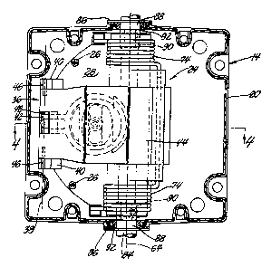
Figure 3 is an enlarged from view of the fluid actuator of figure 2 with the
cover
removed to show internal detail;
Figure 4 is a section taken substantially along the line 4-4 of figure 3
looking in
the direction of the arrows:
Figure 5 is an exploded perspective view of a sub-assembly of the fluid
actuator
that is shown in figure 2; and
Figure 6 is a sectional view of a portion of the hinged stop sign that is
shown in
figure 2.
DESCRIPTION OF THE PREFERRED EMBODIIVVIENT
Referring now to the drawing, figure 1 shows a school bus 10 equipped with a
hinged stop sign 12 and a fluid actuator 14 of the invention. Actuator 14 is
attached to
the body side panel 16 of the bus and pivots stop sign 14 between a stored or
retracted
position adjacent the body side panel 16 and an extended position where stop
sign 12 is
substantially perpendicular to the body side panel 16.
Actuator I4 comprises a housing 18 that has a base 20 and a removable cover
22.
Housing 18 is preferably sealed to protect internal components from the
environment.
The internal components are preferably formed into a subassembly 24 that is
illustrated
best in figure 5 and that is fastened to the bottom of base 20 by screws 26
when cover 22
is removed as shown in figure 3.

CA 02363616 2001-11-22
4
Subassembly 24 comprises a generally planar base member 28 that has a right
cylinder 30 attached to it so that right cylinder 30 has a closed end at the
base member
and an open end spaced from the base member. Piston 32 slides in right
cylinder 30 and
forms a fluid chamber 33 between the piston and the closed end of the right
cylinderthat
communicates with a fluid power source 98 via passage 34 that extends through
the
closed end of cylinder 30 and the bottom of base 20. Cylinder 30 is preferably
an
integral part of base member 28 for economy in which case passage 34 extends
through
base member 28.
The outer end surface of piston 32 has a concentric ball socket 35 with the
ball
socket 35 preferably located at the bottom of a deep cavity 37 in the outer
end surface of
piston 32 that converges to the ball socket 35. Cavity 37 cooperates in
minimizing
height requirements for housing 28 as explained below.
Base member 20 also has a lever arm pivot support 36 that is attached to it to
define a pivot axis 38 that is spaced outwardly of cylinder 30 and that is
substantially
parallel to the generally planar base member 28. The lever arm pivot support
36
comprises laterally spaced supports 40 and a retainer 42 disposed between the
laterally
spaced supports 40. Supports 40 and retainer 42 are preferably an integral
part of base
member 28 for economy. Retainer 42 is also preferably integrally attached to
cylinder
30 by an extension for increased strength.
A lever arm 44 is pivotally attached to the lever arm pivot support 36 at one
end
so that the lever arm swings between a retracted position shown in solid Iine
in figure 4
and an extended position shown in phantom line in figure 4. More specifically,
lever
arm 44 has laterally extending end pins 46 that nest in semi-cylindrical
grooves in the
tops of supports 40 and a concentric center pin 48 that fits under a curved
hook at the top
of retainer 42 to locate the three concentric pins on pivot axis 38. The end
of lever arm
44 and pivot support 36 are resilient enough so that end pins 46 and center
pin 48 can be
snapped into place to facilitate assembly.
The pivotally attached lever arm 44 has a generally concavo-convex body 50
that
extends over cylinder 30 and terminates in a lip 52 that is spaced from
cylinder 30. The
concave side of body 50 faces the open end of cylinder 30 to minimize height

CA 02363616 2001-11-22
requirements for housing 18. The concave side of body 50 also has a semi-
cylindrical
seat 54 that is parallel to pivot axis 38 and that is located near the center
of cylinder 30.
Subassembly 24 fiu-ther includes a pivot arm 56 that has a ball 58 at one end
that
engages ball socket 35 of piston 32 and a cylindrical nose 60 at an opposite
end that
5 engages seat 54 of lever arm 44.
Fluid actuator 14 has a rotor 62 that is rotationally mounted in housing 20 by
the
hinged stop sign 12 for rotation about an axis 64 that is parallel to axis 38
as explained
below. Rotor 62 has a spool 66 at each end and an eccentric arm 68 between the
spools
at the respective ends of the rotor. Eccentric arm 68 engages lip 52 of lever
arm 44. Thus
rotor 62 is rotated substantially 90 degrees from a retracted position shown
in solid line
to an extended position shown in phantom line irt figure 4 when lever arm 44
is moved
between these respective positions by piston 32.
A torsion spring 70 encircles each spool 66 with one end 72 anchored in a hole
in
rotor 66 and an opposite end 74 engaging a groove in the top of spring stop
posts 76 that
are attached to base member 28. Torsion springs 70 bias rotor 62 to the
retracted
position, that is, counterclockwise as shown in figure 4. This also biases
lever arrn 44
counterclockwise to the retracted position shown in solid line in figure 4
where lip 52
engages the bottom of base 20. Posts 76 are preferably an integral part of
base member
28 for economy.
Stop sign 2 mounts rotor 62 rotationally in housing 18 by means of two hollow
L-
shaped arms 80 that are shown and described in detail in U.S. Patents
5,687,500 and
5,796,331 granted to Ronald C. Lamparter November 18, 1997 and August 18, 1998
respectively. As shown in figures 2, 3 and 6, the L-shaped arms 80 are mounted
in the
hollow ends of vertically spaced hinge members 82 of stop sign 12 with a
vertical leg 84
that protrudes through a hole of the respective hinge member 82 and extends
inwardly.
Each vertical leg 84 has a flange 86, a round portion 88 outwardly of the
flange, and a
reduced end portion that is not round, such as the hexagonal end portion 90.
Each round
portion 88 rides in a flanged brass collar 92 while each hexagonal end portion
90 fits into
a correspondingly shaped, concentric recess in the end of a respective spool
66 of rotor
62.

CA 02363616 2001-11-22
6
Base 20 and cover 22 each have two semicircular recesses opposite each other
in
their respective side walls that form two round holes for supporting the
flanged brass
collars 92 when the cover 22 is attached to base 20. The brass collars 20 are
cradled and
held in the recesses of the base 20 by the recesses of the cover 22. The cover
22 thus
acts in the manner of a bearing cap so that the brass collars 92 can be seated
in the
cradles of base 20 when the cover 22 is removed for installation of sub-
assembly 24.
Brass collars 92 are then held in place when cover 22 is attached which
completes the
rotational mounting of rotor 62 in housing 18.
In order to protect the interior of sealed housing 18 against the intrusion of
water,
snow, ice and other deleterious matter into the housing 18 via the upper round
hole for
the upper brass collar 92 and L-shaped arm 80, the upper hinge member 82 of
stop sign
12 preferably has a flared annular skirt 96 that covers the hole and the
flanges of upper
brass collar 92 and arm 80 like an umbrella.
The fluid actuator 14 operates in the following manner. When bus 10 stops to
pick-up or discharge passengers fluid, preferably air, under pressure from
source 98 is
admitted into chamber 33 via a fluid control valve 100 and passage 34. Fluid
power
sources and fluid control valves are well known and thus need not be shown or
described
in detail. Thus fluid power source 98 and fluid control valve 100 are merely
shown
schematically in figure 4. As pressurized fluid is admitted into chamber 33,
chamber 33
expands pushing piston 32 outwardly. Piston 32 in turn pivots lever 44
clockwise from
the retracted position shown in solid line in figure 4 to the extended
position shown in
phantom. Lever 44 in turn pivots rotor 92 clockwise substantially 90°
from the solid
line retracted position to the phantom line extended position. Stop sign 12
being
attached to rotor 92, swing substantially 90° from a stored position
adjacent side wall 16
of bus 10 to an extended or operative position substantially perpendicular to
the side
wall. It should be noted that arm 68 is spaced from cover 22 when sign 12 is
in the
extended position. This allows sign 12 to travel past the extended
perpendicular position
without damaging actuator 14 in case sign 12 pushed past the extended
position. After
the passengers have been taken on or discharged, fluid control valve 100 is
operated to
exhaust chamber 33, and piston 32 is retracted by torsion springs 74 which
also retracts
stop sign 12, rotor 92 and lever 44 to their respective retracted positions.

CA 02363616 2001-11-22
7
While the invention has been illustrated and described in detail in connection
with a hinged stop sign 12, the fluid actuator 14 can also be used for other
hinged safety
devices such as a hinged crossing arm assembly 112 that is shown in figure 1.
Such
crossing arm assemblies are well known and are pivoted substantially
90° from a
retracted position against the front bumper of the bus 10 to an extended
position
substantially perpendicular to the bumper. Moreover, while the fluid actuator
14 is
preferably operated by pressurized air which is clean cheap and easy to
handle, the fluid
actuator 14 may be operated by any gas, by vacuum or even by liquids such as
hydraulic
fluid or oil, with the proper well known modifications.
In other words, many modifications and variations of the present invention are
possible in light of the above teachings. It is therefore, to be understood
that, within the
scope of the appended claims, the invention may be practiced otherwise than as
specifically described.

Representative Drawing
A single figure which represents the drawing illustrating the invention.
Administrative Status

2024-08-01:As part of the Next Generation Patents (NGP) transition, the Canadian Patents Database (CPD) now contains a more detailed Event History, which replicates the Event Log of our new back-office solution.

Please note that "Inactive:" events refers to events no longer in use in our new back-office solution.

For a clearer understanding of the status of the application/patent presented on this page, the site Disclaimer , as well as the definitions for Patent , Event History , Maintenance Fee  and Payment History  should be consulted.

Event History

Description Date
Inactive: IPC deactivated 2011-07-29
Inactive: IPC from MCD 2010-02-01
Inactive: IPC expired 2009-01-01
Application Not Reinstated by Deadline 2007-11-22
Time Limit for Reversal Expired 2007-11-22
Deemed Abandoned - Failure to Respond to Maintenance Fee Notice 2006-11-22
Inactive: Abandon-RFE+Late fee unpaid-Correspondence sent 2006-11-22
Inactive: IPC from MCD 2006-03-12
Inactive: Cover page published 2002-09-03
Application Published (Open to Public Inspection) 2002-09-02
Inactive: First IPC assigned 2002-01-25
Inactive: IPC assigned 2002-01-25
Letter Sent 2001-12-27
Filing Requirements Determined Compliant 2001-12-27
Application Received - Regular National 2001-12-27
Inactive: Filing certificate - No RFE (English) 2001-12-27

Abandonment History

Abandonment Date Reason Reinstatement Date
2006-11-22

Maintenance Fee

The last payment was received on 2005-11-02

Note : If the full payment has not been received on or before the date indicated, a further fee may be required which may be one of the following

  • the reinstatement fee;
  • the late payment fee; or
  • additional fee to reverse deemed expiry.

Please refer to the CIPO Patent Fees web page to see all current fee amounts.

Fee History

Fee Type Anniversary Year Due Date Paid Date
Registration of a document 2001-11-22
Application fee - standard 2001-11-22
MF (application, 2nd anniv.) - standard 02 2003-11-24 2003-11-03
MF (application, 3rd anniv.) - standard 03 2004-11-22 2004-11-03
MF (application, 4th anniv.) - standard 04 2005-11-22 2005-11-02
Owners on Record

Note: Records showing the ownership history in alphabetical order.

Current Owners on Record
TRANSPEC, INC.
Past Owners on Record
JAMES A. HAIGH
RICHARD J. IMINSKI
RONALD C. LAMPARTER
Past Owners that do not appear in the "Owners on Record" listing will appear in other documentation within the application.
Documents

To view selected files, please enter reCAPTCHA code :


To view images, click a link in the Document Description column. To download the documents, select one or more checkboxes in the first column and then click the "Download Selected in PDF format (Zip Archive)" or the "Download Selected as Single PDF" button.

List of published and non-published patent-specific documents on the CPD .

If you have any difficulty accessing content, you can call the Client Service Centre at 1-866-997-1936 or send them an e-mail at CIPO Client Service Centre.


Document
Description 
Date
(yyyy-mm-dd) 
Number of pages   Size of Image (KB) 
Representative drawing 2002-02-14 1 18
Abstract 2001-11-22 1 41
Description 2001-11-22 7 369
Claims 2001-11-22 8 235
Drawings 2001-11-22 3 132
Cover Page 2002-08-30 2 65
Courtesy - Certificate of registration (related document(s)) 2001-12-27 1 113
Filing Certificate (English) 2001-12-27 1 164
Reminder of maintenance fee due 2003-07-23 1 106
Reminder - Request for Examination 2006-07-25 1 116
Courtesy - Abandonment Letter (Request for Examination) 2007-01-31 1 166
Courtesy - Abandonment Letter (Maintenance Fee) 2007-01-17 1 175