Language selection

Search

Patent 2363739 Summary

Third-party information liability

Some of the information on this Web page has been provided by external sources. The Government of Canada is not responsible for the accuracy, reliability or currency of the information supplied by external sources. Users wishing to rely upon this information should consult directly with the source of the information. Content provided by external sources is not subject to official languages, privacy and accessibility requirements.

Claims and Abstract availability

Any discrepancies in the text and image of the Claims and Abstract are due to differing posting times. Text of the Claims and Abstract are posted:

  • At the time the application is open to public inspection;
  • At the time of issue of the patent (grant).
(12) Patent: (11) CA 2363739
(54) English Title: PORTABLE LAMP ASSEMBLY
(54) French Title: LAMPE PORTATIVE
Status: Deemed expired
Bibliographic Data
Abstracts

English Abstract

A portable lamp assembly which comprises a fuel containing container and a globe therefore, the globe having a plurality of convex reflective surfaces on an inner surface thereof to maximize light output. The globe also functions as a protective member for the fuel containing container when in a stored position for transportation.


French Abstract

Lampe portative comprenant un contenant de combustible et un globe de lampe, le globe comportant plusieurs surfaces réfléchissantes convexes sur une surface intérieure de celui-ci afin de maximiser la lumière produite. Le globe sert également d'élément protecteur pour le contenant de combustible lorsqu'il est en position de rangement aux fins de transport.

Claims

Note: Claims are shown in the official language in which they were submitted.


The embodiments of the invention in which an exclusive property or privilege
is
claimed are as follows:


1. A fuel burning assembly comprising a container designed to contain a fuel
and a
globe therefore;

said container having a container side wall and a container top wall;

said container top wall having an opening therein, an externally threaded neck

surrounding said opening;

said globe comprising a continuous globe side wall sized to fit externally of
said
container side wall, said globe side wall having an interior face and an
exterior face; and
at least one member extending inwardly from said interior face and being
arranged

such that said member will rest on an upper portion of said container when
said globe is
placed over said container whereby said globe may function as a chimney.

2. The fuel burning assembly of Claim 1 further including a wick assembly,
said
wick assembly including a wick and a wick holder, said wick holder being sized
to fit
within said opening in said container top wall and to seat on said externally
threaded
neck.

3. The fuel burning assembly of Claim 1 wherein both said container side wall
and
said globe side wall have a generally cylindrical configuration.

4. The fuel burning assembly of Claim 3 wherein said at least one member
extending
inwardly from said interior face comprises a plurality of spaced tabs
extending inwardly
from said interior face.

5. The fuel burning assembly of Claim 3 wherein said globe side wall is sized
and
configured such that when said globe is placed over said container, an air
space is
provided between said container and said globe side wall to permit air flow
therethrough.


-7-


6. The fuel burning assembly of Claim 3 wherein said globe side wall has a
slightly
tapered configuration to snugly retain said container for transportation
thereof.

7. The fuel burning assembly of Claim 3 wherein said globe side wall has a
height
substantially equal to the height of said container.

8. The fuel burning assembly of Claim 1 wherein said globe is constructed of a

transparent plastic material.

9. The fuel burning assembly of Claim 3 wherein an inner face of said globe
side wall
has a plurality of bevels to aid in light reflection.


-8-

Description

Note: Descriptions are shown in the official language in which they were submitted.


CA 02363739 2001-11-26

PORTABLE LAMP ASSEMBLY
FIELD OF THE INVENTION

The present invention relates to a lamp and more particularly, relates to a
portable
lamp utilizing a liquid fuel.

BACKGROUND OF THE INVENTION

Liquid fuel burners are known in the art and have been used for a number of
years.
They are generally considered to be a disposable item and have been used both
for
providing lighting and for warming foods in chafing dishes and the like.
Typically, the
burner includes a sealed container in which the fuel is stored and a wick that
passes
upwardly through the lid of the container. The fuel passes up through the wick
and the
wick is lit. When the fuel is exhausted, the container is typically discarded
and replaced
with a new unit.

Most disposable liquid fuel burners are relatively simple in structure and
preset in
the factory to provide for an optimum flame height by exposing a limited lamp
wick
above the top of the burner. The wick assembly, intended only for use with the
single
can, is relatively simple. One disadvantage of many of the disposable liquid
fuel burners
is the inherent danger in transporting the same. In many instances, it is
desirable to
transport the liquid fuel burner as, for example, when using the same on
camping trips or
the like. However, known liquid fuel burners generally are not designed for
such use and
particularly so when a relatively volatile fuel is utilized.

SUMMARY OF THE INVENTION

It is an object of the present invention to provide a disposable liquid fuel
burner
suitable for lighting purposes and which is compact in nature.

-1-


CA 02363739 2001-11-26

It is a further object of the present invention to provide a disposable liquid
fuel
burner for lighting purposes which is readily transportable.

In one embodiment of the present invention, there is provided a fuel burning
assembly comprising a container designed to contain a fuel and a globe
therefore, the
container having a container side wall and a container top wall, the container
top wall
having an opening therein, an externally threaded neck surrounding the
opening, the
globe comprising a continuous globe side wall sized to fit externally of the
container side
wall, the globe side wall having an interior face and an exterior face and at
least one
member extending inwardly from the interior face and being arranged such that
the
member will rest on an upper portion of the container when the globe is placed
over the
container whereby the globe may fu.nction as a chimney.

The container having the liquid fuel therein, according to the present
invention, is
formed of a metallic material and is preferably cylindrical in configuration.
Located
centrally in the upper side wall is an aperture which is designed to receive a
wick device.
Surrounding the aperture is a neck, the neck preferably having external screw
threads
formed thereon to receive a cap. The top of the neck is designed to receive
the wick
assembly which will sit thereon.

The wick assembly includes the wick, which is preferably of a woven material,
and a cover member, as previously mentioned, will include a flange which will
seat on
the top of the wall surrounding the aperture. Centrally of the cover member
there will be
a raised land portion with a lower portion surrounding the raised land
portion. In the
center of the raised land portion there will be provided an aperture for the
wick to extend
therethrough. The lower portion surrounding the raised land portion will
include a drain

-2-


CA 02363739 2001-11-26

back aperture formed therein such that any fuel thereon will drain back into
the container.
In the preferred embodiment, there is also provided an intermediate cover
member
designed to cover a portion of the wick holder. In particular, the cover
member may be
designed to fit interiorly of the upstanding wall of the wick retainer and
have a portion
thereof designed to enclose the wick per se. In so doing, leakage during
transportation is
prevented.

There is also provided a chimney, the chimney serving two functions. During
the
transport, the fuel container is designed to fit within the chimney which
provides
additional protection therefore and also allows for a compact storage of the
device.
During the use, the chimney is designed to seat on the top of the fuel
container and
extend above the flame to provide protection for the flame. At the same time,
a lower
portion extends downwardly about the upper side wall of the container while
still
permitting a supply of air to the wick. Preferably the chimney is formed of a
clear heat
resistant material and more preferably of a heat resistant plastic material
such as marketed
under the trademark Lexan . To maximize the lighting effect, the chimney is
preferably
given refractive properties and to this end, may comprise a cylindrical wall
having
beveled portions on the interior surface thereof.

BRIEF DESCRIPTION OF THE DRAWINGS

Having thus generally described the invention, reference will be made to the
accompanying drawings illustrating an embodiment thereof, in which:

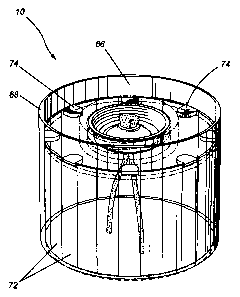
Figure 1 is a perspective view of a fuel burning assembly according to one
embodiment of the present invention;

Figure 2 is a side elevational view of the globe portion thereof;
-3-


CA 02363739 2001-11-26

Figure 3 is a cross sectional view of the fuel container portion thereof;

Figure 4 is a side elevational view of the globe and fuel container in a
storage
position;

Figure 5 is a cross sectional view thereof;

Figure 6 is a side elevational view showing the fuel container and globe in an
operative position; and

Figure 7 is a perspective view of the wick and cap component of the fuel
container.

DESCRIPTION OF THE PREFERRED EMBODIMENTS

Referring to the drawings in greater detail and by reference characters
thereto,
there is illustrated in Figure 1 a fuel burning assembly generally designated
by reference
numeral 10 and which fuel burning assembly is designed to be used for lighting
purposes.

Assembly 10 includes a fuel container generally designated by reference
numeral
12 and a globe generally designated by reference numeral 14.

Fuel container 12 comprises a can 16 having a bottom wall 18, a side wall 20
and
a top wall 22, the hole being formed in a conventional manner. Situated on top
wall 22
and formed intrically therewith is a neck 24 having external threads 26 formed
thereon.
Turning to Figure 7, there is illustrated a wick assembly which is generally

designated by reference numeral 28. Wick assembly 28 includes an insert 30
sized to fit
within neck 24. Insert 30 includes a side wall 32 having a flange 34 extending
outwardly
at the upper end thereon and designed to seat on the upper periphery of neck
24 of can
16. At the lower end of side wall 32 of insert 30, there is provided an
upwardly sloping
bottom wall 36. Located centrally of sloping bottom wall 36 is an inner side
wall 38

-4-


CA 02363739 2008-12-18

which extends to an inner top wa1140 having a wick aperture 42 formed therein.
Mounted
in wick aperture 42 is a wick 44 designed to extend into can 16 and the fuel
contained
therein.

Formed within sloping bottom wall and located proximate to its point of
joinder
with side wall 32 are one or more drainage apertures 46 to permit drainage of
any fuel
back into can 16.

A cover member 50 includes a top wall 52 and a downwardly depending skirt or
side wall 54 having internal threads 56 formed thereon and which internal
threads are
designed to meet with external threads 26 on neck 24.

Globe 14 is formed of a transparent material and may be conveniently formed of
a
transparent plastic material. Globe 14 includes a minor portion 64 having
first and second
bevel segments 66 and 68 formed therein. Thus, minor portion 64 is generally
circular in
configuration, both on the interior and exterior surface, except for bevel
segments 66

which have a convex configuration on the inner surface thereof.

A major portion 70 of globe 14 has a plurality of equally configured bevel
segments 72 formed thereon. Bevel segments 72 are formed on the interior
surface of
major portion 70 and comprise a plurality of concave configurations.

Separating minor portion 64 and major portion 70 are a plurality of inwardly
extending tabs 74.

In use, the arrangement is such that minor portion 64 of globe 14 will fit
over the
upper portion of can 16 with tabs 74 sitting on the rim of can 16. Major
portion 70
extends above can 16 and the beveled portions are designed to reflect the
maximum

-5-


CA 02363739 2001-11-26

amount of light. The arrangement is such that air may flow upwardly between
minor
portion 64 and can 16.

For transport purposes, the globe is inverted such that major portion 70 is in
the
lower position. The distance between tabs 74 and the marginal edge of major
portion 70
is substantially equal to the height of can 16. In this configuration, minor
portion 64 will
extend above the neck 24 and cover 50. Globe 14 is also arranged such that
there will be
frictional engagement between the area of major portion 70 adjacent tabs 74
and the rim
of can 16.

It will be understood that the above described embodiments are for purposes of
illustration only and that changes or modifications may be made thereto
without
departing from the spirit and scope of the invention.

-6-

Representative Drawing
A single figure which represents the drawing illustrating the invention.
Administrative Status

For a clearer understanding of the status of the application/patent presented on this page, the site Disclaimer , as well as the definitions for Patent , Administrative Status , Maintenance Fee  and Payment History  should be consulted.

Administrative Status

Title Date
Forecasted Issue Date 2009-10-06
(22) Filed 2001-11-26
(41) Open to Public Inspection 2003-05-26
Examination Requested 2006-11-27
(45) Issued 2009-10-06
Deemed Expired 2011-11-28

Abandonment History

Abandonment Date Reason Reinstatement Date
2007-11-26 FAILURE TO PAY APPLICATION MAINTENANCE FEE 2008-02-18

Payment History

Fee Type Anniversary Year Due Date Amount Paid Paid Date
Application Fee $150.00 2001-11-26
Maintenance Fee - Application - New Act 2 2003-11-26 $50.00 2003-11-18
Maintenance Fee - Application - New Act 3 2004-11-26 $50.00 2004-11-19
Maintenance Fee - Application - New Act 4 2005-11-28 $50.00 2005-11-28
Request for Examination $400.00 2006-11-27
Maintenance Fee - Application - New Act 5 2006-11-27 $100.00 2006-11-27
Reinstatement: Failure to Pay Application Maintenance Fees $200.00 2008-02-18
Maintenance Fee - Application - New Act 6 2007-11-26 $100.00 2008-02-18
Maintenance Fee - Application - New Act 7 2008-11-26 $100.00 2008-11-20
Final Fee $150.00 2009-07-08
Maintenance Fee - Patent - New Act 8 2009-11-26 $100.00 2009-11-26
Owners on Record

Note: Records showing the ownership history in alphabetical order.

Current Owners on Record
PECOSKIE, PHIL
Past Owners on Record
None
Past Owners that do not appear in the "Owners on Record" listing will appear in other documentation within the application.
Documents

To view selected files, please enter reCAPTCHA code :


To view images, click a link in the Document Description column. To download the documents, select one or more checkboxes in the first column and then click the "Download Selected in PDF format (Zip Archive)" or the "Download Selected as Single PDF" button.

List of published and non-published patent-specific documents on the CPD .

If you have any difficulty accessing content, you can call the Client Service Centre at 1-866-997-1936 or send them an e-mail at CIPO Client Service Centre.


Document
Description 
Date
(yyyy-mm-dd) 
Number of pages   Size of Image (KB) 
Representative Drawing 2002-03-21 1 8
Cover Page 2003-05-05 1 28
Abstract 2001-11-26 1 11
Description 2001-11-26 6 241
Claims 2008-12-18 2 58
Drawings 2008-12-18 3 62
Description 2008-12-18 6 236
Claims 2001-11-26 2 60
Drawings 2001-11-26 3 58
Representative Drawing 2009-03-30 1 13
Cover Page 2009-09-09 1 36
Assignment 2001-11-26 2 73
Fees 2003-11-18 1 24
Prosecution-Amendment 2008-12-18 6 137
Fees 2004-11-19 1 21
Fees 2005-11-28 1 24
Fees 2006-11-27 1 21
Prosecution-Amendment 2006-11-27 1 20
Prosecution-Amendment 2008-08-13 1 31
Correspondence 2009-07-08 1 24