Language selection

Search

Patent 2364119 Summary

Third-party information liability

Some of the information on this Web page has been provided by external sources. The Government of Canada is not responsible for the accuracy, reliability or currency of the information supplied by external sources. Users wishing to rely upon this information should consult directly with the source of the information. Content provided by external sources is not subject to official languages, privacy and accessibility requirements.

Claims and Abstract availability

Any discrepancies in the text and image of the Claims and Abstract are due to differing posting times. Text of the Claims and Abstract are posted:

  • At the time the application is open to public inspection;
  • At the time of issue of the patent (grant).
(12) Patent Application: (11) CA 2364119
(54) English Title: PROFILE PRINTING WITH ADDITIVE TECHNOLOGY
(54) French Title: IMPRESSION DE PROFIL A L'AIDE D'UNE TECHNOLOGIE ADDITIVE
Status: Deemed Abandoned and Beyond the Period of Reinstatement - Pending Response to Notice of Disregarded Communication
Bibliographic Data
(51) International Patent Classification (IPC):
  • B41M 07/00 (2006.01)
  • B41L 23/00 (2006.01)
(72) Inventors :
  • HUFFER, SCOTT W. (United States of America)
  • SCHUETZ, JEFFREY M. (United States of America)
(73) Owners :
  • SONOCO DEVELOPMENT, INC.
(71) Applicants :
  • SONOCO DEVELOPMENT, INC. (United States of America)
(74) Agent: MCCARTHY TETRAULT LLP
(74) Associate agent:
(45) Issued:
(22) Filed Date: 2001-11-27
(41) Open to Public Inspection: 2002-05-27
Examination requested: 2006-09-07
Availability of licence: N/A
Dedicated to the Public: N/A
(25) Language of filing: English

Patent Cooperation Treaty (PCT): No

(30) Application Priority Data:
Application No. Country/Territory Date
09/724,992 (United States of America) 2000-11-27

Abstracts

English Abstract


A method of printing and the resulting printed product is disclosed which
provides a
three dimensional raised look and feel without requiring expensive embossing
rollers. A
surface tension lowering additive is added to ink or clear resin or varnish,
and the ink is
printed onto a substrate in a pattern of substantially parallel lines, leaving
spaces of substrate
exposed between the lines of ink or clear resin or varnish. The clear resin or
varnish may
also be printed on a clear film and ink is then printed on the resin or
varnish. The film can
then be laminated to a metallized film, foil or other reflective surface. A
resin coating is
applied over the printed pattern. The resin collects in the areas of exposed
substrate due to
the differential surface tension. The result is a pattern of raised resin
profile ridges oriented
along the pattern of ink lines.


Claims

Note: Claims are shown in the official language in which they were submitted.

-5-
Claims
What is claimed is:
1. A printing process comprising the steps of:
providing a printing ink;
adding a surface tension lowering additive to the ink,
printing the ink onto a substrate in a pattern,
drying the ink,
applying a coating over the substrate and the ink,
allowing the coating to flow from the ink printed areas to the non- printed
areas, and
allowing the coating to dry in the form of raised profile ridges.
2. The printing process of claim 1 wherein the ink is printed in a pattern of
substantially parallel lines.
3. The printing process of claim 2 wherein the ink pattern is printed such
that
non-printed areas remain between the substantially parallel lines of printed
ink.
4. The printing process of claim 2 wherein the coating forms raised ridges
oriented along the printed ink pattern.
5. The printing process of claim 1 wherein the coating is a resin.
6. The printing process of claim 5 wherein the resin coating is clear.
7. The printing process of claim 1 wherein the coating is a varnish.
8. The printing process of claim 1 wherein the coating is a pattern of colored
inks.
9. The printing process of claim 1 wherein the coating is a pattern of
metallic
ink.
10. The printing process of claim 1 wherein the substrate is a reflective
surface.
11. The printing process of claim 10 wherein the reflective surface is a
metallized
film.

-6-
12. The printing process of claim 10 wherein the reflective surface is a foil.
13. The printing process of claim 1 wherein the substrate is a clear film.
14. The printing process of claim 13 wherein the ink and coating are reverse
printed on the clear film and further comprising the step of securing the
reverse printed film
to a second substrate.
15. The printing process of claim 14 wherein the second substrate is a
metallized
film.
16. A printing process as claimed in claim 1 wherein the additive is hydroxy-
modified polyether silane.
17. A printing process comprising the steps of:
providing a printing ink;
adding a surface tension lowering additive to an ink;
printing the ink onto a substrate in a pattern of substantially parallel lines
such
that non-printed areas remain between the substantially parallel lines of
printed ink;
drying the ink;
applying a coating over the substrate and the ink,
allowing the coating to flow from the ink printed areas to the non- printed
areas until the coating forms raised ridges oriented along the lines of the
ink pattern, and
drying the coating.
18. A printing process as claimed in claim 17 wherein the substrate is a
metallized
film.
19. A printing process as claimed in claim 17 wherein the additive is hydroxy-
modified polyether silane.
20. A printed product comprising:
an ink having a surface tension lowering additive therein printed in a pattern
onto a substrate, and
a coating applied over the ink pattern, such that the coating flows away from
the printed ink pattern and accumulates in the non-printed areas in the form
of raised profile
ridges.

-7-
21. The printed product of claim 20, wherein the ink pattern comprises
substantially parallel lines having spaces therebetween.
22. The printed product of claim 21, wherein the coating forms a pattern of
raised
ridges oriented along the lines of the printed ink pattern.
23. The printed product of claim 20 wherein the coating foams a pattern of
raised
ridges adjacent the printed ink pattern.
24. The printed product of claim 20 wherein the additive is hydroxy-modified
polyether silane.
25. The printed product of claim 20 wherein the substrate is a metallized
film.
26. The printed product of claim 25 wherein the ink additive is a hydroxy-
modified polyether silane.
27. A printing process comprising the steps of:
providing a printing ink;
providing a coating;
adding a surface tension lowering additive to the coating;
printing the coating onto a substrate in a pattern of substantially parallel
lines
such that non-printed areas remain between the substantially parallel lines of
printed coating;
drying the coating;
applying the ink over the substrate and the coating,
allowing the ink to flow from the coating printed areas to the non- printed
areas until the ink forms raised ridges oriented along the lines of the
coating pattern, and
drying the ink.
28. A printing process as claimed in claim 27 wherein the substrate is a
metallized
film.
29. A printing process as claimed in claim 27 wherein the additive is hydroxy-
modified polyether silane.

Description

Note: Descriptions are shown in the official language in which they were submitted.


CA 02364119 2001-11-27
_1-
PROFILE PRINTING WITH ADDITIVE TECHNOLOGY
Field of the Invention
The present invention relates to a method of printing and printed products.
More
specifically, the present invention relates to a method of printing profile
ridges by applying
resin to a low surface tension ink.
Background of the Application
In today's marketplace, products are often distinguished as much by the
packaging in
which they are presented as the quality of the product itself. A package which
catches the eye
of the consumer is therefore very desirable. To that end, increasingly
colorful and creative
graphics have been applied to packaging in an attempt to distinguish one
package, and hence
one product, from another.
One popular graphic with visual appeal for consumers is the hologram.
Holograms
present a three dimensional image to the consumer. Unfortunately, holograms
are expensive
to produce, requiring high precision embossing equipment and tools. The
capital expense
required to produce holograms is high enough that holograms are often used as
a security
device.
Simpler embossing methods can be used at lower cost than holograms to produce
a
graphic with a textured or raised look and feel. Embossing can produce
interesting visual
effects when a clear profile is embossed over an image. The underlying image
appears
differently from various viewing angles due to refraction of light through the
embossed
profile. However, even simple embossing equipment requires a significant
capital
expenditure.
Thus, there is a need for a simpler, less expensive technology for printing
packaging
material with a visually appealing, textured look and feel. The present
invention provides
311237

CA 02364119 2001-11-27
-2-
such a printing method, eliminating the need for embossing rollers, while
providing a profile
pattern of raised ridges over printed matter.
Summary of the Invention
The present invention provides a printing process and a printed product in
which ink
is combined with an additive that lowers the surface tension of the dried ink
film. The
enhanced ink is printed onto a substrate in a pattern of substantially
parallel lines and allowed
to dry. A clear resin or varnish is applied over or under the dried ink, and
because of the
difference in surface tension between the ink film and the substrate, the
resin flows away
from the ink film. The resin cures in a series of raised ridges oriented along
the printed profile
lines.
For reverse printed applications, the additive is formulated into the clear
resin or
varnish. The clear resin pattern is printed on a clear web. The clear pattern
is dried and the
ink is printed on top of the dried clear resin. This ink flows away from the
clear resin due to
the difference in surface tension, forming patterns of raised ink. This
reverse-printed film is
then laminated to a second film to complete the overall structure.
Brief Description of the Drawings
For the purpose of illustrating the invention, there is shown in the drawings
a form
which is presently preferred; it being understood, however, that this
invention is not limited
to the precise arrangements and instrumentalities shown.
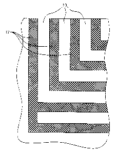
Figure 1 is a top view of a portion of printed matter according to the present
invention.
Figure 2 is a cross section showing clear resin applied to a substrate and ink
lines
according to the present invention before any flow has occurred in the resin
due to different
surface tensions.
Figure 3 is a cross section of printed matter according to the present
invention.
311237

CA 02364119 2001-11-27
-3-
Detailed Description of the Drawings
In order to more clearly illustrate the invention, Figures 1-3 show a section
of printed
matter according to the present invention. Before printing, the ink is
combined with an
additive which lowers the surface tension of the dried ink film. One such
additive is a
hydroxy-modified polyether silane manufactured and sold by BYK-Chemie. The
additive
enhanced ink 12 is printed over the substrate 10 in a pattern of substantially
parallel profile
lines, leaving spaces between adjacent lines of ink so that the substrate
remains exposed. The
substrate is preferably a non-printed metallized film, foil, or other
reflective surface.
Figure 1 shows a section of substrate 10 which has been overprinted with ink
12 in a
profile pattern. The particular printing method used to apply the ink to the
substrate is not
important, and those of ordinary skill in the art will recognize that a
variety of printing
methods are available. One example of a suitable printing method is the
rotogravure process.
Rotogravure is preferable because it produces highly accurate images, while
allowing for
high press and production speeds. Rotogravure cylinders engraved by a laser
engraver will
yield both the production volume and continuous channels necessary to produce
the desired
visual effect.
The laser engraver is capable of engraving deep continuous channel for the
ink.
Mechanical engraving with a diamond stylus will only produce large cells with
narrow
channels of a much smaller volume.
A resin 14 is applied over the printed ink pattern area 12. The resin is
preferably clear
when dried. Figure 2 shows a cross section of some printed matter immediately
after the resin
14 has been applied. The resin 14 is in contact with both the printed dried
ink film 12 and the
substrate 10 between lines of ink 12. Because the surface tension of the dried
ink film 12 is
lower than the surface tension of the substrate 10, the resin 14 flows away
from the dried ink
film 12 and toward the areas of exposed substrate 10.
Figure 3 shows a cross section of printed matter according to the invention
after the
resin 14 has completed its flow. The resin 14 has collected in the areas of
exposed substrate
311237

CA 02364119 2001-11-27
-4-
between the profile lines of ink 12. Thus, the resin 14 forms raised ridges 16
that are
oriented along the patterned lines of ink 12. Because the resin is clear or
translucent,
refraction of light through the resin will cause the printed matter to change
appearance when
viewed from different angles. The resin 14 is allowed to set to form lasting
raised profile
ridges 16 oriented along the lines of the ink pattern 12.
Without the additive in the ink the resin would normally flow out to a
continuous film
and would not yield a refraction pattern as contemplated by the raised ridges
in the present
invention. Other visual effects can be created by the use of various colored
or metallic inks
that may be substituted for the clear profile resin. For reverse printed
applications, the clear
resin is pattern applied with the additive first and then the ink is printed
to form the patterns.
It should be understood that when producing the printed structure on press,
independent registration control is possible for the individual profile
stations, resulting in
better overall registration. Further, by the use of a laser engraver, highly
accurate patterns
can be created. Also, more volume of the resin or coating can be deposited on
the surface
due to the large volume of cells produced on the laser engraver. This large
volume is
possible with the present invention substantially without the occurrence of
"flow outs".
It is contemplated that further variations of the present invention are
possible by the
use of four color printing techniques and by the addition of scuff resistant
coatings or the like.
Scuff resistance may also be achieved by reverse printing the ink and resin
coating on a clear
film and applying the film to a second substrate.
The present invention may be embodied in still further specific forms without
departing from the spirit or essential attributes thereof and, accordingly,
reference should be
made to the appended claims, rather than to the foregoing specification, as
indicating the
scope of the invention.
311237

Representative Drawing
A single figure which represents the drawing illustrating the invention.
Administrative Status

2024-08-01:As part of the Next Generation Patents (NGP) transition, the Canadian Patents Database (CPD) now contains a more detailed Event History, which replicates the Event Log of our new back-office solution.

Please note that "Inactive:" events refers to events no longer in use in our new back-office solution.

For a clearer understanding of the status of the application/patent presented on this page, the site Disclaimer , as well as the definitions for Patent , Event History , Maintenance Fee  and Payment History  should be consulted.

Event History

Description Date
Inactive: IPC expired 2014-01-01
Application Not Reinstated by Deadline 2009-11-27
Time Limit for Reversal Expired 2009-11-27
Inactive: Abandoned - No reply to s.30(2) Rules requisition 2009-02-26
Deemed Abandoned - Failure to Respond to Maintenance Fee Notice 2008-11-27
Inactive: S.30(2) Rules - Examiner requisition 2008-08-26
Amendment Received - Voluntary Amendment 2006-11-20
Letter Sent 2006-09-28
All Requirements for Examination Determined Compliant 2006-09-07
Request for Examination Requirements Determined Compliant 2006-09-07
Request for Examination Received 2006-09-07
Inactive: IPC from MCD 2006-03-12
Inactive: Correspondence - Formalities 2005-09-26
Inactive: Office letter 2005-06-09
Revocation of Agent Requirements Determined Compliant 2005-06-09
Appointment of Agent Requirements Determined Compliant 2005-06-09
Inactive: Office letter 2005-06-08
Application Published (Open to Public Inspection) 2002-05-27
Inactive: Cover page published 2002-05-26
Inactive: IPC assigned 2002-02-05
Inactive: First IPC assigned 2002-02-05
Inactive: Filing certificate - No RFE (English) 2002-01-08
Letter Sent 2002-01-08
Application Received - Regular National 2002-01-08

Abandonment History

Abandonment Date Reason Reinstatement Date
2008-11-27

Maintenance Fee

The last payment was received on 2007-10-30

Note : If the full payment has not been received on or before the date indicated, a further fee may be required which may be one of the following

  • the reinstatement fee;
  • the late payment fee; or
  • additional fee to reverse deemed expiry.

Patent fees are adjusted on the 1st of January every year. The amounts above are the current amounts if received by December 31 of the current year.
Please refer to the CIPO Patent Fees web page to see all current fee amounts.

Fee History

Fee Type Anniversary Year Due Date Paid Date
Registration of a document 2001-11-27
Application fee - standard 2001-11-27
MF (application, 2nd anniv.) - standard 02 2003-11-27 2003-09-30
MF (application, 3rd anniv.) - standard 03 2004-11-29 2004-09-23
MF (application, 4th anniv.) - standard 04 2005-11-28 2005-09-26
Request for examination - standard 2006-09-07
MF (application, 5th anniv.) - standard 05 2006-11-27 2006-11-14
MF (application, 6th anniv.) - standard 06 2007-11-27 2007-10-30
Owners on Record

Note: Records showing the ownership history in alphabetical order.

Current Owners on Record
SONOCO DEVELOPMENT, INC.
Past Owners on Record
JEFFREY M. SCHUETZ
SCOTT W. HUFFER
Past Owners that do not appear in the "Owners on Record" listing will appear in other documentation within the application.
Documents

To view selected files, please enter reCAPTCHA code :


To view images, click a link in the Document Description column. To download the documents, select one or more checkboxes in the first column and then click the "Download Selected in PDF format (Zip Archive)" or the "Download Selected as Single PDF" button.

List of published and non-published patent-specific documents on the CPD .

If you have any difficulty accessing content, you can call the Client Service Centre at 1-866-997-1936 or send them an e-mail at CIPO Client Service Centre.


Document
Description 
Date
(yyyy-mm-dd) 
Number of pages   Size of Image (KB) 
Representative drawing 2002-02-07 1 24
Abstract 2001-11-26 1 21
Description 2001-11-26 4 179
Claims 2001-11-26 3 102
Drawings 2001-11-26 2 52
Courtesy - Certificate of registration (related document(s)) 2002-01-07 1 113
Filing Certificate (English) 2002-01-07 1 164
Reminder of maintenance fee due 2003-07-28 1 106
Reminder - Request for Examination 2006-07-30 1 117
Acknowledgement of Request for Examination 2006-09-27 1 176
Courtesy - Abandonment Letter (Maintenance Fee) 2009-01-21 1 174
Courtesy - Abandonment Letter (R30(2)) 2009-06-03 1 165
Correspondence 2005-06-01 11 496
Correspondence 2005-06-07 1 14
Correspondence 2005-06-08 1 16
Fees 2005-09-25 1 24
Correspondence 2005-09-25 1 24
Fees 2006-11-13 1 23
Fees 2007-10-29 1 25