Note: Descriptions are shown in the official language in which they were submitted.
S v
CA 02364277 2001-12-05
Sabau,Ioan A.
Method and Apparatus for Decreasing Gassing and Decay of Insulating Oil in
Transformers
_ Page 1 of 6
Inventor: IOAN A. SABAU
Title: METHOD AND APPARATUS FOR DECREASING GASSING AND
DECAY OF INSULATING OIL IN TRANSFORMERS
Field of the Invention
The Invention relates to the field of power transformers. In particular, the
Invention, in
one embodiment, is a method and apparatus to decrease the gassing and decay of
mineral insulating oil used in power transformers.
The Invention has particular application, but is not thereby limited, in the
field of power
transformers, where it is useful to use a self-sufficient and environmentally
friendly
method or apparatus to prolong the service reliability and life expectancy of
medium,
high and extra high voltage power transformers.
Background of the Invention
It is commonly understood that insulating oil is used in power transformers. A
number
of methods exist for various treatments relating to transformer oil. See
Canadian Patent
No. 1,227,026 (United States Patent No. 4,498,992), which claims a process for
treating
contaminated transformer oil by heating the oil and passing it through an
absorber, then
chilling the oil, and Canadian Patent No. 2,143,580, a method for eliminating
the
oxidation of dielectric fluid using a continuous flow of inert gas and an
expansion
chamber. Also see United States Patent No. 5,942,121, which claims a method
for
filtering and removing products of aging in oil using a mechanical filter, an
adsorbent
and degassing process, and United States Patent No. 4,806,276, an additive for
transformer oils comprised of a non-ionic fluorosurfactant and a halogenated
hydrocarbon. Further, United States Patent No. 6,193,786 claims a method and
device
for portable degasification, reducing the concentration of combustible gases
in insulating
oils, by forming a combustible gas-inert mixture and venting the mixture.
It is also known to use a gas or liquid analyzer with a transformer. See
Canadian Patent
No. 2,014,619, which claims a method and apparatus for analyzing gases in
dissolved
insulating oil, involving the use of separate gas stripping zones
communicating with the
CA 02364277 2001-12-05
Sabau,Ioan A.
Method and Apparatus for Decreasing Gassing and Decay of Insulating Oil in
Transformers
Pale 2 of 6
flame ionization detector side and thermal conductivity detector side of
chromatograph.
Also see Canadian Patent No. 1,082,774, which claims an apparatus and method
for
detecting and measuring fault gases in oil insulated transformers using a cell
loop and
hollow tubes, and Canadian Patent No. 2,054,616, a method of determining the
stability
of insulating oil by ionizing and determining the concentration of free
radicals in oil, and
absorption spectra of oil before and after ionization of the oil.
Several technologies exist that attempt to prevent the deficiency of the
absorption of air
that inhibits the service reliability and shortens the life expectancy of
power
transformers. Due to the direct contact with the outside atmosphere, the
mineral
insulating oil naturally dissolves 10% air in volume. Under the impact of heat
and
electrical stress, certain vulnerable components of this complex blend of
hydrocarbons
decomposes and generates broken molecules, known as free radicals, having each
an
unpaired electron. Since the dissolved oxygen is also a free radical with two
unpaired
electrons, its inevitable contamination with the broken hydrocarbons chains
generate a
variety of decay products that irreversibly damages the solid insulation. In
one known
method, oxidation inhibitors are added to the insulating oil in order to
increase its
resistance to oxidation. These additives improve the chemical stability for a
certain
period of time. Another known system is to seal the transformer by using a
flexible
membrane or a static nitrogen membrane cushion above the oil.
Summary of the Invention
It is an object of the Invention to overcome limitations in the prior art of
power
transformers. In essence, oxidation inhibitors are ineffective in the long run
and the
effectiveness of oxidation inhibitors in general has a number of limitations.
Also, the
present analytical procedures, such as interfacial tension (IFT), are outdated
as they are
not sensitive enough to monitor the step by step oxidation process of oil. A
further
limitation in the prior art is that in sealed transformers, the dissolved
gases that arise
under the impact of electrical stress are trapped inside the tank of the
transformer. A
certain amount diffuses in the gas space while the rest accumulates in the
liquid
insulators, making the interpretation of dissolved gas analysis (DGA)
questionable.
These closed systems have also experienced many mechanical problems and are
therefore limited mainly to the United States.
CA 02364277 2001-12-05
Sabau, Ioan A.
Method and Apparatus for Decreasing Gassing and Decay of Insulating Oil in
Transformers
Page 3 of 6
The prior art inadequately addresses the need for an environmentally friendly
and
efficient power transformer with an extended life. None of the prior art
discloses a
practical invention that effectively utilizes a power transformer with a
membrane
nitrogen generator, a trace gas analyzer and an absorption tower, nor a power
transformer that does not require an oil expansion chamber or gas relay.
The Invention relates to a method and apparatus designed to decrease the
gassing and
decay of insulating mineral oil in high voltage power transformers by
implementing a
membrane nitrogen generator that produces a nitrogen blanket, a trace gas
analyzer and
an absorption tower filled with Fuller's earth (the kidney) to existing
transformer models
or to a totally new transformer design that does not require an oil expansion
chamber or
gas relay. The Invention eliminates the oxidation process currently used for
oil and any
related oxygen analysis, reclaims the oil used within the transformer, and
increases the
speed and accuracy of the detection of purity of gas and problems that may
occur within
the transformer by the increased speed of diffusion - thus ultimately
increasing the
reliability of the transformer, the detection of problems and the life of the
transformer,
and at the same time decreasing the required maintenance and oil use.
Under the new method and apparatus used by the Invention, a nitrogen generator
produces a nitrogen blanket and any change in the purity of the dynamic
nitrogen
blanket above the surface of the oil is monitored by a highly sensitive trace
gas analyzer
as a substitute for taking periodic oil samples to detect the existence of
electrical failures
by dissolved gas analysis. The dynamic nitrogen blanket prevents the oxidation
decay
of the oil and signals an imminent incipient electrical failure. Instead of
taking oil
samples twice a year for dissolved gas analysis and interpreting the results
based upon
empirical methods, this on-line detection of an incipient electrical failure
can enhance
the service reliability of power transformers. In addition, the
environmentally friendly
reclamation of oil is obtained via the absorption tower and the initial
properties of the oil
are maintained, thus both preventing the decline of the transformer service
reliability
and extending its life expectancy. By eliminating the dissolved oxygen that
deteriorates
the chemical stability of oil and selectively removing the solid suspensions
that are
harmful to the solid insulation, the purity of liquid insulation can be
maintained at its
initial level for the entire lifetime of the power transform. The oxidation
process is
CA 02364277 2001-12-05
Sabau, Ioan A.
Method and Apparatus for Decreasing Gassing and Decay of Insulating Oil in
Transformers
Page 4 of 6
eliminated and the oxygen decreases until it disappears, thus also eliminating
the need
to analyze the oxygen.
In order to arrest the oxidation decay process of the mineral insulating oil
in the tank
and expansion chamber of free breathing high voltage transformers, a flow of
99.8%
purity nitrogen is supplied by a gas compressor and a membrane nitrogen
generator,
and it is continuously injected at one end of the expansion chamber into its
gas space
and released at the other end into the atmosphere through several trace gas
analyzers for
oxygen, hydrogen, carbon monoxide, carbon dioxide and hydrocarbons. The fault
gases
generated by a potential incipient electrical failure diffuse faster into the
flow of pure
nitrogen, reducing the delay between the occurrence of the gas evolvement and
its
detection by the gas analyzer.
According to Henry's law, the content of gases dissolved in oil of a power
transformer is
proportional with the partial pressure of gases above its surface. Therefore,
when gases
are generated inside a transformer tank due to the decomposition of oil under
the
impact of an incipient electrical failure (hot spot or partial discharge), the
arising gases
that dissolve in the oil will partially diffuse into the dynamic nitrogen
blanket,
modifying the base line recorded by each gas analyzer that continuously
monitor the
purity of emerging gas. As a result, while the dynamic nitrogen blanket
transforms an
existing free breathing transformer into an essentially closed one, arresting
the access of
atmospheric oxygen to the surface of the oil without modifying the original
design, it
also signals with a relatively short delay any material change in the chemical
composition of emitted gas, any fault gas evolvement caused by an incipient
electrical
failure. Since the breakdown of a hydrocarbon chain generates both gases and
chemically reactive large free radicals, the combination with each other
produces
insoluble decay products (x-wares) capable of clogging the pores of paper
insulation. To
prevent the accumulation of these solid suspensions that reduce the ability of
oil to
dissipate heat and favour the formation of hot spots, a pump continuously re-
circulates
the oil through an adsorption tower filled with Fuller's Earth.
Essentially, the method utilized in the Invention provides a system whereby
the initial
purity of the oil is maintained for the entire lifetime of the transformer and
the liquid
insulation provides a decay product that may damage the solid insulation by
forming
CA 02364277 2001-12-05
Sabau,Ioan A.
Method and Apparatus for Decreasing Gassing and Decay of Insulating Oil in
Transformers
Page 5 of 6
hot spots or by encouraging the occurrence of partial discharge. This lessens
the decay
of mineral insulating oil while. in service and eliminates the current
practice of the
selective removal of decay products which arise in service conditions when the
deterioration of oil properties exceeds certain limits. The Invention also
enables the
frequent on-line monitoring of fault gases generated under the impact of
incipient
electrical failures. A further economic advantage of the Invention is that
desiccators are
no longer necessary.
According to conventional transformer design, the role of an expansion chamber
is to
minimize the surface of oil in contact with the gas space connected to the
outside
atmosphere by a back and forfh circulation pipe, and to introduce the gas
relay between
the tank and the conservator. The application of the new transformer apparatus
consisting of a one way dynamic nitrogen blanket system free of both oxygen
and
moisture renders the expansion chamber redundant.
These and other objects and advantages of the Invention are apparent in the
following
description of embodiments of the Invention, which is not intended to limit in
any way
the scope or the claims of the Invention.
Description of the Invention
The following described embodiments of the Invention display preferred
compositions
but are not intended to limit the scope of the Invention. It will be obvious
to those
skilled in the art that variations and modifications may be made without
departing from
the scope and essential elements of the Invention.
A known embodiment of the Invention is a method comprised of a transformer,
gas
compressor, nitrogen membrane generator, oil, gases, oil expansion chamber,
trace gas
analyzer, gas relay, transformer tank, oil pump, reactivable adsorption tower
and
Fuller's Earth.
Another known embodiment of the Invention is a transformer apparatus comprised
of
gas compressor, nitrogen membrane generator, oil, gases, trace gas analyzer,
gas relay,
transformer tank, oil pump, reactivable adsorption tower and Fuller's Earth.
CA 02364277 2001-12-05
Sabau,Ioan A.
Method and Apparatus for Decreasing Gassing and Decay of Insulating Oil in
Transformers
Page 6 of 6
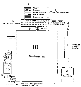
Brief Description of Drawings
Figure One (1) illustrates an embodiment of the Invention as a method
comprised of
transformer 1, gas compressor 2, nitrogen membrane generator 3, nitrogen 4,
oil
expansion chamber 5, oil 6, trace gases 7, trace gas analyzer 8, gas relay 9,
transformer
tank 10, oil pump 11, reactivable adsorption tower 12 and Fuller's Earth 13.
Figure Two (2) illustrates an embodiment of the Invention as an apparatus
comprised of
a transformer 1, with gas compressor 2, nitrogen membrane generator 3,
nitrogen 4, oil
6, trace gases 7, trace gas analyzer 8, transformer tank 10, oil pump 11,
reactivable
adsorption tower 12 and Fuller's Earth 13.
In the foregoing descriptions, the Invention has been described in known
embodiments.
However, it will be evident that various modifications and changes may be made
without departing from the broader scope and spirit of the Invention.
Accordingly, the
present specifications and embodiments are to be regarded as illustrative
rather than
restrictive.
The descriptions here are meant to be exemplary and not limiting. It is to be
understood
that a reader skilled in the art will derive from this descriptive material
the concepts of
this Invention, and that there are a variety of other possible
implementations; all
components used in the Invention may be comprised of any suitable material or
materials and substitution of different specific components for those
mentioned here
will not be sufficient to differ from the Invention described where the
substituted
components are functionally equivalent.