Language selection

Search

Patent 2364313 Summary

Third-party information liability

Some of the information on this Web page has been provided by external sources. The Government of Canada is not responsible for the accuracy, reliability or currency of the information supplied by external sources. Users wishing to rely upon this information should consult directly with the source of the information. Content provided by external sources is not subject to official languages, privacy and accessibility requirements.

Claims and Abstract availability

Any discrepancies in the text and image of the Claims and Abstract are due to differing posting times. Text of the Claims and Abstract are posted:

  • At the time the application is open to public inspection;
  • At the time of issue of the patent (grant).
(12) Patent Application: (11) CA 2364313
(54) English Title: COLLAPSIBLE STRUCTURE FOR PATIOS AND DRIVEWAYS
(54) French Title: STRUCTURE RABATTABLE POUR TERRASSES ET VOIES D'ACCES A LA PROPRIETE
Status: Deemed Abandoned and Beyond the Period of Reinstatement - Pending Response to Notice of Disregarded Communication
Bibliographic Data
(51) International Patent Classification (IPC):
  • E04B 1/343 (2006.01)
  • E04H 1/12 (2006.01)
  • E04H 6/04 (2006.01)
  • E04H 12/22 (2006.01)
(72) Inventors :
  • GU, HAO RAN (Canada)
(73) Owners :
  • HAO RAN GU
(71) Applicants :
  • HAO RAN GU (Canada)
(74) Agent: NELLIGAN O'BRIEN PAYNE LLP
(74) Associate agent:
(45) Issued:
(22) Filed Date: 2001-12-11
(41) Open to Public Inspection: 2002-03-14
Examination requested: 2001-12-11
Availability of licence: N/A
Dedicated to the Public: N/A
(25) Language of filing: English

Patent Cooperation Treaty (PCT): No

(30) Application Priority Data: None

Abstracts

English Abstract


A collapsible and removable roof-like structure or enclosure is provided. The
collapsible
structure includes a plurality of collapsible sections, each section having
two vertical support
members having lower end portions and two longitudinal side panel members with
a side panel
member being attached to an associated vertical support member. Each side
panel member has
a top edge and side edges. The collapsible structure includes a longitudinal
top panel member
having opposed edges with the top panel member being hingedly attached at one
of the opposed
edges to the top edge of one of the side panel members and hingedly attached
at the other of the
opposed edges to the top edge of the other side panel member. The top panel
member includes
two longitudinal panel members being hinged together at adjacent end edges and
each of the
plurality of collapsible sections is of a steadily varying size so that the
side edges of each panel
of each collapsible section snugly overlaps with the side edges of each panel
of an adjacent
collapsible section. The collapsible structure includes tube members which can
be embedded
in the ground for receiving the lower end portion of the vertical support
members.
10


Claims

Note: Claims are shown in the official language in which they were submitted.

THE EMBODIMENTS OF THE INVENTION IN WHICH AN EXCLUSIVE PROPERTY
OR PRIVILEGE IS CLAIMED ARE DEFINED AS FOLLOWS:
1. A collapsible, portable structure, comprising:
(a) a plurality of collapsible sections, each section including two vertical
support
members having lower end portions, two longitudinal side panel members, a side
panel member being attached to an associated vertical support member, each
side
panel member having a top edge and side edges; and
(b) a longitudinal top panel member having opposed edges, said top panel
member being
hingedly attached at one of the said opposed edges to the top edge of one of
said side
panel members and hingedly attached at the other of said opposed edges to the
top
edge of the other side panel member.
2. A collapsible, portable structure, comprising:
(a) a plurality of collapsible sections, each section including two vertical
support
members having lower end portions, two longitudinal side panel members, a side
panel member being attached to an associated vertical support member, each
side
panel member having a top edge and side edges;
(b) a longitudinal top panel member having opposed edges, said top panel
member being
hingedly attached at one of the said opposed edges to the top edge of one of
said side
panel members and hingedly attached at the other of said opposed edges to the
top
edge of the other side panel member; and
(c) means for supporting said vertical support members substantially
vertically in spaced
apart relation when assembled, whereby each of said collapsible sections can
be
7

positioned in side-edge to side-edge relation with an adjacent collapsible
section to
form an extended longitudinal structure.
3. The collapsible structure according to claim 1 or 2, wherein said top panel
member is two
longitudinal panel members being hinged together at adjacent end edges.
4. The collapsible structure according to claim 1, 2 or 3, wherein each of
said plurality of
collapsible sections is of a steadily varying size so that the side edges of
each panel of each
collapsible section snugly overlaps with the side edges of each panel of an
adjacent
collapsible section.
5. The collapsible structure according to claim 2, 3 or 4 including tube
members which can be
embedded in the ground for receiving said lower end portion of said vertical
support
members.
6. The collapsible structure according to claim 5, wherein said tube members
including locking
means for locking said vertical support member within said tube member.
7. The collapsible structure according to claim 6, wherein said vertical
support member includes
a slot located in said lower portion thereof, said locking means includes said
tube member
provided with a retractable boss member engagable into said slot.
8

8. The collapsible structure according to any one of claims 1 to 7, wherein
one of said side panel
members of each collapsible section includes clips for locking said side panel
members and
said top panel members together when the collapsible section is collapsed.
9. The collapsible structure according to any one of claims 1 to 8, wherein
the top panels of the
collapsible section forming the ends of said collapsible structure are
provided with
upstanding rims along the edges of the panels to prevent water dripping from
the top panels
over the side edges thereof.
10. The collapsible structure according to any one of claims 1, 2, 3, 5, 6, 7,
8 and 9, wherein said
side-edge to side-edge relation comprises the side edges of panel members in
adjacent
collapsible sections abutting each other.
9

Description

Note: Descriptions are shown in the official language in which they were submitted.


CA 02364313 2001-12-11
COLLAPSIBLE STRUCTURE FOR PATIOS AND DRIVEWAYS
FIELD OF THE INVENTION
The present invention relates to collapsible, portable structures or
enclosures for patios
and driveways.
BACKGROUND OF THE INVENTION
In northern climates where winter is accompanied by considerable snowfall, it
is
advantageous to provide temporary shelter for driveways or patios during the
winter months.
Portable structures such as tents, ice fishing huts or prefabricated homes are
well known in the
art. Many of these structures are large, bulky and difficult for one person to
assemble and
1 S disassemble. In addition, most of these collapsible structures come in a
fixed size and cannot
readily be expanded to suit the particular size or dimensions of a driveway or
patio.
For these reasons, there is a need for new and improved means to provide
temporary,
expandable and collapsible covers or shelters for driveways and patios during
winter months
which can be easily assembled and disassembled and stored when not required.
SUMMARY AND OBJECTS OF THE INVENTION
An object of the present invention is to provide a collapsible and removable
structure
which can be installed on a driveway or patio in winter to protect the
driveway or patio from
snow. In spring, they can be collapsed, folded and stored in a garage or
basement.
1

CA 02364313 2001-12-11
The present invention provides a plurality of collapsible sections. Each
section includes
two vertical support members having lower end portions and two longitudinal
side panel
members with a side panel member being attached to an associated vertical
support member.
Each side panel member has a top edge and side edges. The collapsible
structure includes a
longitudinal top panel member having opposed edges with the top panel member
being hingedly
attached at one of the opposed edges to the top edge of one of the side panel
members and
hingedly attached at the other of the opposed edges to the top edge of the
other side panel
member. The collapsible structure includes means for supporting the vertical
support members
substantially vertically in spaced apart relation when assembled. Each of the
collapsible sections
can be positioned in side-edge to side-edge relation with an adj acent
collapsible section to form
an extended longitudinal structure.
Preferably the top panel member is two longitudinal panel members being hinged
together at adjacent end edges and each of the plurality of collapsible
sections is of a steadily
varying size so that the side edges of each panel of each collapsible section
snugly overlaps with
the side edges of each panel of an adjacent collapsible section. The
collapsible structure includes
tube members which can be embedded in the ground for receiving the lower end
portion of the
vertical support members.
In another aspect of the invention the tube members include locking means for
locking
the vertical support member within the tube member. Specifically, the vertical
support member
includes a slot located in the lower portion thereof and locking means
includes the tube member
being provided with a retractable boss member engagable into the slot.
While used specifically for sheltering from snow, this invention can also
expand the
space of a garage, providing a simple, lightweight and economical
construction.
2

CA 02364313 2001-12-11
BRIEF DESCRIPTION OF THE DRAWINGS
The collapsible roof forming the present invention will now be described, by
example
only, reference being the accompanying drawings, in which:
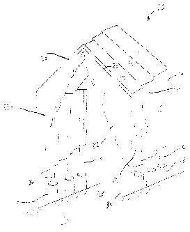
Figure 1 is a perspective view of the collapsible roof of the present
invention showing a series
of collapsible enclosure panels joined together;
Figure 2 is a perspective view of one of the collapsible enclosure panels of
Figure 1;
Figure 3 is a perspective view of the roof enclosure panel as shown in Figure
2 but in the
collapsed position; and
Figure 4 is an enlarged detailed view, broken away, of the circled portion 4
in Figure 2 of the
roof enclosure support column and ground supporting member.
DETAILS DESCRIPTION OF THE INVENTION
In the following description of the collapsible roof, in reference to the
drawings, like
numerals refer to like parts. Referring to Figures 1 to 3, a collapsible patio
or driveway roof is
shown generally at 10. Collapsible structure 10 comprises of plurality of
collapsible sections,
with three such units 12, 14 and 16 being shown in Figure 1. Collapsible
section 12 forms the
front enclosure unit and includes a vertical extending rim 20 to prevent water
dripping from
running down over the opening of the unit. A flexible tarp or canvas 22
attached to the edge of
section 12 forms a closure member for the collapsible roof. Similarly, the
collapsible section
forming the other end of the enclosure is also provided with a rim around the
edge and a flexible
tarp or canvas to form a closure. Each collapsible section is supported by
vertical uprights 30
which when the collapsible structure 10 is assembled are inserted into tubes
28 partially buried
3

CA 02364313 2001-12-11
in the ground along the sides of the driveway or patio 26. Alternatively, the
bottom portions of
uprights 30 could be driven directly into the ground instead of using tubes.
Figure 2 shows a perspective view of collapsible section 14 comprising
vertical upright
supports 30 which support the section when it is erected. Side panels 32 and
34 are attached to
upright supports 30 and form vertical side panels when the section is erected.
The roof of
collapsible unit 14 includes two roof panels 38 and 40 connected together by a
hinge 42 at the
apex of the corresponding roof section. Side panel 32 and roof panel 38 are
hinged together by
a hinge 46 and roof panel 40 and side panel 34 are hinged together by a hinge
44. Side panel 34
includes clips 50 and 52 located at the ends of panel 34 which are used to
lock the collapsed
enclosure unit 14 together, best seen in Figure 3. Alternatively, the top or
roof panel may be a
single longitudinal panel extending horizontally between the side panels when
the collapsible
unit is assembled.
With reference to the embodiment of the invention shown in Figure 1, each of
the
collapsible sections making up a complete collapsible structure is a slightly
different size so that
a plurality of the units fit together with the edges of each panel of the
section tightly or snugly
overlapping with the associated panels of the adjacent collapsible sections on
either side thereof.
In this embodiment, each collapsible section would have a number clearly
inscribed on one of
the panels clearly indicative of the size of the section. For example, a
structure constructed from
ten collapsible sections would have the sections consecutively numbered with
increasing
numbers from one to ten corresponding to increasing size of the sections.
It will be understood however by those skilled in the art that all the
collapsible sections
could be made the same size and other means for locking the collapsible
sections together could
be used. For example, hook and eye units could be installed on the interior of
the collapsible
units to hold adjacent collapsible sections together with the edges of the
panels of adjacent
4

CA 02364313 2001-12-11
sections abutting each other. Weather stripping, foam or other types of sealer
may be affixed
along the edges of the panels to provide a seal when adjacent collapsible
sections are assembled
together.
Referring to Figure 4, an enlarged detail view of the tube 28 is shown. Tube
28 includes
a pair of spring-loaded locking mechanisms 60 mounted in opposing relationship
in the wall of
tube 28 having projections 64 which engage cut-out sections 62 of columns 30
to lock collapsible
panel 10 (Figure 1) in place in the tubes. When the collapsible structure is
assembled, the user
inserts the column 30 into tube 28 whereby the column engages the arcuate
surface 66 of locking
mechanism 60 pushing it outwards so the column drops into tube 28. The column
30 is locked
in place when the spring loaded projections 64 pop into cut-out portions 62 of
columns 30. Thus,
to erect structure 10, the user can plug column 30 into tube 28, then column
30 is automatically
locked when cut-out section 62 reaches the position of the arcuate surface 66.
To collapse roof
structure 10, the user can simply push button 60 to disengage projections 64.
Each collapsible
panel unit is then folded as shown in Figure 3 and clips 50 and 52 engage the
folded panels to
lock them together. The folded units may then be stored or conveniently
transported. The
detailed blowup of Figure 4, shows projection or boss 64 having a spring 80
having a
longitudinal arm 82 wrapped around a pivot rod 84 and engaged against an arm
86 attached to
button 60. Pushing button 60 causes spring portion 82 to pivot about pivot
point 84 thereby
retracting boss 64 from the slot in vertical upright 30.
The different parts of each collapsible section may be made of plastic or
alternatively a
light metal such as aluminium may be used. As previously discussed, each
collapsible section
is preferably of a slightly smaller size than the preceding unit in the
serially assembled collapsible
units and the greater the number of collapsible units the larger the
enclosure. This design
advantageously prevents water from falling down to the driveway. While used
specifically for
5

CA 02364313 2001-12-11
sheltering from snow, this invention can also expand the space of a garage,
providing a simple,
lightweight and economical construction.
While the collapsible and portable structure constructed in accordance with
the present
invention has been described and illustrated with respect to the preferred
embodiments, those
skilled in the art will appreciate that numerous variations may be made
without departing from
the scope of the invention disclosed herein.
6

Representative Drawing
A single figure which represents the drawing illustrating the invention.
Administrative Status

2024-08-01:As part of the Next Generation Patents (NGP) transition, the Canadian Patents Database (CPD) now contains a more detailed Event History, which replicates the Event Log of our new back-office solution.

Please note that "Inactive:" events refers to events no longer in use in our new back-office solution.

For a clearer understanding of the status of the application/patent presented on this page, the site Disclaimer , as well as the definitions for Patent , Event History , Maintenance Fee  and Payment History  should be consulted.

Event History

Description Date
Inactive: IPC from MCD 2006-03-12
Inactive: Dead - No reply to s.30(2) Rules requisition 2004-06-03
Application Not Reinstated by Deadline 2004-06-03
Deemed Abandoned - Failure to Respond to Maintenance Fee Notice 2003-12-11
Inactive: Abandoned - No reply to s.30(2) Rules requisition 2003-06-03
Inactive: S.30(2) Rules - Examiner requisition 2002-12-03
Amendment Received - Voluntary Amendment 2002-10-18
Inactive: S.30(2) Rules - Examiner requisition 2002-09-26
Application Published (Open to Public Inspection) 2002-03-14
Inactive: Cover page published 2002-03-13
Letter sent 2002-01-18
Advanced Examination Determined Compliant - paragraph 84(1)(a) of the Patent Rules 2002-01-18
Inactive: First IPC assigned 2002-01-17
Inactive: IPC assigned 2002-01-17
Inactive: Filing certificate - RFE (English) 2002-01-14
Filing Requirements Determined Compliant 2002-01-14
Application Received - Regular National 2002-01-09
Early Laid Open Requested 2002-01-09
Letter Sent 2002-01-09
Inactive: Advanced examination (SO) fee processed 2002-01-03
Request for Examination Requirements Determined Compliant 2001-12-11
All Requirements for Examination Determined Compliant 2001-12-11

Abandonment History

Abandonment Date Reason Reinstatement Date
2003-12-11

Fee History

Fee Type Anniversary Year Due Date Paid Date
Application fee - small 2001-12-11
Request for examination - small 2001-12-11
Advanced Examination 2002-01-03
Owners on Record

Note: Records showing the ownership history in alphabetical order.

Current Owners on Record
HAO RAN GU
Past Owners on Record
None
Past Owners that do not appear in the "Owners on Record" listing will appear in other documentation within the application.
Documents

To view selected files, please enter reCAPTCHA code :


To view images, click a link in the Document Description column. To download the documents, select one or more checkboxes in the first column and then click the "Download Selected in PDF format (Zip Archive)" or the "Download Selected as Single PDF" button.

List of published and non-published patent-specific documents on the CPD .

If you have any difficulty accessing content, you can call the Client Service Centre at 1-866-997-1936 or send them an e-mail at CIPO Client Service Centre.


Document
Description 
Date
(yyyy-mm-dd) 
Number of pages   Size of Image (KB) 
Representative drawing 2002-03-11 1 10
Description 2002-10-18 6 244
Claims 2002-10-18 2 80
Description 2001-12-11 6 243
Abstract 2001-12-11 1 31
Drawings 2001-12-11 4 76
Description 2001-12-11 3 92
Cover Page 2002-03-11 2 49
Acknowledgement of Request for Examination 2002-01-09 1 178
Filing Certificate (English) 2002-01-14 1 164
Reminder of maintenance fee due 2003-08-12 1 106
Courtesy - Abandonment Letter (R30(2)) 2003-08-12 1 167
Courtesy - Abandonment Letter (Maintenance Fee) 2004-02-05 1 176
Correspondence 2002-01-09 1 34