Language selection

Search

Patent 2364481 Summary

Third-party information liability

Some of the information on this Web page has been provided by external sources. The Government of Canada is not responsible for the accuracy, reliability or currency of the information supplied by external sources. Users wishing to rely upon this information should consult directly with the source of the information. Content provided by external sources is not subject to official languages, privacy and accessibility requirements.

Claims and Abstract availability

Any discrepancies in the text and image of the Claims and Abstract are due to differing posting times. Text of the Claims and Abstract are posted:

  • At the time the application is open to public inspection;
  • At the time of issue of the patent (grant).
(12) Patent Application: (11) CA 2364481
(54) English Title: PORTABLE HEATER
(54) French Title: APPAREIL DE CHAUFFAGE PORTATIF
Status: Deemed Abandoned and Beyond the Period of Reinstatement - Pending Response to Notice of Disregarded Communication
Bibliographic Data
(51) International Patent Classification (IPC):
  • F24H 3/06 (2006.01)
(72) Inventors :
  • PELONIS, KOSTA L. (United States of America)
(73) Owners :
  • KOSTA L. PELONIS
(71) Applicants :
  • KOSTA L. PELONIS (United States of America)
(74) Agent: KIRBY EADES GALE BAKER
(74) Associate agent:
(45) Issued:
(22) Filed Date: 2001-11-30
(41) Open to Public Inspection: 2002-05-30
Examination requested: 2006-11-30
Availability of licence: N/A
Dedicated to the Public: N/A
(25) Language of filing: English

Patent Cooperation Treaty (PCT): No

(30) Application Priority Data:
Application No. Country/Territory Date
60/250,249 (United States of America) 2000-11-30

Abstracts

English Abstract


A portable heater includes a radiator having multiple tubular units and an
electric heating element in the radiator for heating the diathermal fluid. A
fan
positioned above the seated radiator directs air on the upper portions of the
tubular
units to enhance convection of the fluid.


Claims

Note: Claims are shown in the official language in which they were submitted.

-5-
I claim:
1. A portable heater comprising:
(a) a sealed radiator containing a diathermal fluid, the radiator including
a plurality of tubular radiator units, the tubular radiator units having
respective
upper portions and respective lower portions;
(b) at least one electric heating element positioned within the sealed
radiator;
(c) a fan positioned above the sealed radiator for directing air on the
upper portions of the tubular radiator units the fan being effective to cool
the upper
portions of the tubular units to enhance thermal convection of the diathermal
fluid
within the tubular radiator units.
2. A portable heater according to claim 1 wherein the fan comprises a
centrifugal fan.
3. A portable heater according to claim 2 further comprising an electric motor
for driving the centrifugal fan.
4. A portable heater according to claim 3 wherein the electric motor operates
at low rpm.
5. A portable heater according to claim 4 wherein the electric motor operates
at less than 2500 rpm.
6. A portable heater according to claim 5 wherein the electric motor operates
at less than 1000 rpm.
7. A portable heater according to claim 1 further comprising a cover enclosing
the fan.

Description

Note: Descriptions are shown in the official language in which they were submitted.


CA 02364481 2001-11-30
PORYABL-E HEATER
BACKGROUND OP THE INVENTION
f=ield of the Invention
Th~ present invention relates to portable heating devices.
2. Brief Description of th~a Prior Art
As home hating oil and natural gas prices fluctuate upward, there is an
increasing need for efficient, inexpensive portable heaters. Portable heaters
provide flexibility to enhance the comfort of specific rooms within a
centrally-heated
horns, without incurring the cost of employing the central furnace to heat the
entire
home, fr~Giuding unoccupied rooms.
Portabfsr heaters are wail known in the art. One well-known type of
portable heater is the portable radiator-type heater. F~eamplss of portable
radiator-
type heaters are disGosed in U.S, Patents 4,483,974, 4,870,253, 5,9t~B,498,
and D ,
341,ti'S~4,
2b Portable radiator heaters typically include a set of flattened, tubular
radiator
units filled with a diathermal fluid such as mineral oil. The radiator units
are joined
proximate their tops by arr~~upper header and proximate their bottoms by a
lawer
headers. The headers permit the thermal fluid to how between radiator units.
An
electric heating element is provided in the lower header, The heating element
serves to warm the diathermal fluid ~o that the fluid circulates through the
radiator
unii~ by thermal convection, to warm the air adjacent to the exterior surfaces
of the
tubular radiator units.
U.~, Patent 4,879,253 disdvses a portable radiator type heater equipped
with an air-cdrculating fan under the radiator units. The fan optionally
includes
resistive heating elements far preheating air expelled by the fan. The
orientation of
the exhaust of the fan can be varied from a generally vertical position in
which the
fan exhaust Is directed upward through the radiator units, to a generally
horizontal
position in which the exhaust is directed outward away from the radiator
units.
The greater the number of radiator units, the greater their collective surface
area, the greater the rate of heat transs'er from the radiator unit to the
surrounding
air. Thus, it is desirable to employ as many radiator units as practical, On
the
other hand. .each additional radiator unit adds to the cost of manufacturing
the

CA 02364481 2001-11-30
-2.
portable heater. Thus, there is a need for a portable radiator type heater
that
employs a reduced number of radiator units, yet provides effective heat
transfer
from the radiator units to the room air.
SUMMARY QF THE INVENTION
The present invention provides a portable heater comprising a sealed
radiator containing a diathermal fluid. The radiator inGudes a plurality of
tubular
radiator units. Each of the tubular radiator units has respective upper
portions and
respective lower portions. The portable heater further includes at least one
electric
heating elemerd positioned within the sealed radiator, as well as a fan
positioned
above the sealed radiator for directing air on the upper portions of the
tubular
radiator units, The fan is effective to cool the upper portions of the tubular
units.
This enhances thermal convection of the diathermal fluid within the tubular
radiator
units.
The present invention thus advantageously reduces the surtace area
required for transferring heat from the electric heating element via the
diathermal
fluid to the room air. Thus, at least one fewer tubular radiator unit is
required, with
a ronc~amitant reduction in the cost of manufacturing the portable heater. In
addition, the radiator can be maintained at a cooler temperature, It has been
calculated that for every 10 degrees Celsius that the operating temperature
can be
reduced, the power consumption per tubular radiator unit can be concomitantly
reduced by 250 watts. Thus, the power consumption of the portable heater can
be
advantageously reduced. Further, the present invention provides more rapid
heat
~5 distribcrtion from the portable heater to the room.
preferably, the heater includes a centrifugal fan driven by an electric motor,
It is also preferred that a quiet fan be employed. To that end, it is
preferred that
the electric motor operates at low rpm, preferably at less than 250Q rpm, and
more
preferably at less than 1000 rpm. Preferably, the portable heater inGudes a
cover
enclosing the fan.
DRIEF DESCRIPTION OF THE DRAWING
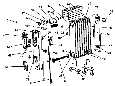
Figure 1 is an exploded perspective view of a portable heater according to
the present invention, showing assembly of the heater and the major components
thereof.

CA 02364481 2001-11-30
-3-
DETAIt_ED DESCRIPTIpN
referring now to the figure in which like reference numerals represent like
ale~m~nt in each of the several views, there is shown in Fig. 1 a portable
heater 10
of the present invenkion. The portable heater 10 includes a central radiator
20
formed from a plurality of generally flat, tubular radiator units 22 fanned
from a
suitable material such as sheet metal.
Proximate the top of each of the radiator units 22 and symmetrically
extending outwardly of each side thereof there are fomned a pair of upper
header
elements 23, each in this farm of a truncated cone. Similarly, proximate the
bottom
of each of the radiator units 10 and symmetrically extending outwardly from
each
side thereof there are formed a pair of lower header elements 25, each in the
form
of a truncated cone.
When the radiator 20 is assembled, each of the upper header elements 23
are collinear, thus forming an upper header section 24, and providing a flaw
path
for fluid in between the interiors of the tubular radiator units 22, the
exteryor faang
upper leader elements of the first and last radiator units 22 being sealed.
Similarly, when the radiator 20 is assembled, each of the lower header
elements
are collinear, thus forming a lower header section 28, and providing a flow
path
20 for fluid in between the interiors of the tubular radiator units 22, The
portion of the
radiator 20 proximate the top of the radiator 20 can be referred to as the
upper
portion 28 and the portion of the radiator 20 proximate the bottom of the
radiator 20
can be referred to as the lower portion 30.
An electrical resistanrx-heating element 40 is positioned inside the radiator
25 20 wifihin the lower header section 26, The radiator 20 is filled with a
diathermal
fluid such as an inert oil, for example, mineral ail, for transferring heat
from the
electrical resistance heating element 40 to the exterior surfaces of the
radi~rtor
units 22. The interior of the radiator 20 is sealed against leakage of the
diathermal
fluid.
A wiring harness 32 connects the heating element 40 with a source of
external electrical power via a power cord 34 and with various electric
control
devices. A thermostat 4z controls operation of the electrical resistance-
heating
element 40. A thermal fuse 44 is also provided positioned proximate the
radiator
20 as a safety device against overheating of the radiator 20. In addition, a
tip-over
switch 4s is provided to cut off current to the heating element 40 should the
Portable heater 10 be accidentally tipped over. A temperature limiter 48 is
also

CA 02364481 2001-11-30
-4-
provided as a safety measure. A power switch 50 is provided to control overall
operation of the portable heater 10.
A fan 52 is provided proximate the top of the radiator 20. The fan 52
includes a generally cylindrical housing S6 with a downwardly directly outlet
for
blowing air over the upper portion 28 of the radiator 20, The fan also
includes a
generalhy cylindrical "squircel cage"-type fan blade assembly 54, supported at
one
end by a suitable bearing 62. The fan 52 includes a motor 62 tfiat drives the
fan
blade assembly 54 through a suitable drive 58. A baffle plate 64 is provided
in
between the fan housing 58 and the fan motor 62. The fan motor 62 is mounted
above an insulation plate fib for thermally insulating the tan motor 62 from
the
radiator 20. Preferably, the fan molar 62 is of a low rpm type, preferably
having an
operating speed of less than 2500 rpm and more preferably less than 1500 rpm,
so
that the fan 52 operates quietly.
The portable heater 10 also includes a front cover 68 and a rear cover 74
each formed from a suitable material, such as by molding a suitable heat-
resistant
therma~plastic material. The front cover 68 is adapted to receive a control
pane! 70
proximate the top of the front cover 68, the control panel 70 having a
plurality of
apertures formed therein for receiving knobs 92 for controlling the power
switch 50
and tt~e thermostat 42, as well a pilot lamp 94 for indicating operation of
the
portable heater 10. The control panel 70 also include$ a molded-in handle 72,
and
the rear cover 74 includes an aperture for receiving a corresponding handle
76, to
permit the portable heater 10 to be moved. The front panel 88 is also adapted
to
recoive a cord wrap plate 98 proximate the bottom of the front panel for
wrapping
the electrical power cord 34. A pair of wheel units 96 fitted with suitable
wheels or
castors is provided under the radiator 20 to facilitate moving the portable
heater
10. In addition, a generally "U"-shaped top cover 80 is provided for covering
the
upper portion 28 of the radiator 28 and enGosing the fan 52, The top cover 80
is
provided with a plurality of louvers 82 adapted to cool the top cover 80 and
to
permit air to drawn into the fan enGosure. The front cover 68 and the rear
cover
3U 74 are also provided with a plurality of louvers 78 to permit air
cir4ulation and
cooling.
It will be recognized by those skilled in the art that charges may be made in
the above described embodiment of the invention without departing from the
broad
inventive concepts thereof. It is understood, therefore, that this invention
is hot
limited to the particular embodiments disclosed, but is intended to cover ail
modifications, which are within the scope and spirit of the invention.

Representative Drawing
A single figure which represents the drawing illustrating the invention.
Administrative Status

2024-08-01:As part of the Next Generation Patents (NGP) transition, the Canadian Patents Database (CPD) now contains a more detailed Event History, which replicates the Event Log of our new back-office solution.

Please note that "Inactive:" events refers to events no longer in use in our new back-office solution.

For a clearer understanding of the status of the application/patent presented on this page, the site Disclaimer , as well as the definitions for Patent , Event History , Maintenance Fee  and Payment History  should be consulted.

Event History

Description Date
Inactive: Dead - No reply to s.30(2) Rules requisition 2012-07-10
Application Not Reinstated by Deadline 2012-07-10
Deemed Abandoned - Failure to Respond to Maintenance Fee Notice 2011-11-30
Inactive: Abandoned - No reply to s.30(2) Rules requisition 2011-07-11
Inactive: S.30(2) Rules - Examiner requisition 2011-01-10
Amendment Received - Voluntary Amendment 2010-09-10
Inactive: S.30(2) Rules - Examiner requisition 2010-03-12
Amendment Received - Voluntary Amendment 2009-09-23
Inactive: S.30(2) Rules - Examiner requisition 2009-03-23
Letter Sent 2007-01-15
All Requirements for Examination Determined Compliant 2006-11-30
Request for Examination Requirements Determined Compliant 2006-11-30
Request for Examination Received 2006-11-30
Inactive: Office letter 2005-12-13
Appointment of Agent Requirements Determined Compliant 2005-12-13
Revocation of Agent Requirements Determined Compliant 2005-12-13
Letter Sent 2005-12-13
Inactive: Office letter 2005-12-13
Appointment of Agent Request 2005-11-02
Reinstatement Requirements Deemed Compliant for All Abandonment Reasons 2005-11-02
Revocation of Agent Request 2005-11-02
Deemed Abandoned - Failure to Respond to Maintenance Fee Notice 2004-11-30
Application Published (Open to Public Inspection) 2002-05-30
Inactive: Cover page published 2002-05-29
Inactive: First IPC assigned 2002-02-06
Inactive: Correspondence - Formalities 2002-01-25
Amendment Received - Voluntary Amendment 2002-01-25
Inactive: Filing certificate - No RFE (English) 2002-01-10
Filing Requirements Determined Compliant 2002-01-10
Application Received - Regular National 2002-01-10

Abandonment History

Abandonment Date Reason Reinstatement Date
2011-11-30
2004-11-30

Maintenance Fee

The last payment was received on 2010-11-29

Note : If the full payment has not been received on or before the date indicated, a further fee may be required which may be one of the following

  • the reinstatement fee;
  • the late payment fee; or
  • additional fee to reverse deemed expiry.

Please refer to the CIPO Patent Fees web page to see all current fee amounts.

Fee History

Fee Type Anniversary Year Due Date Paid Date
Application fee - small 2001-11-30
MF (application, 2nd anniv.) - small 02 2003-12-01 2003-11-17
MF (application, 3rd anniv.) - small 03 2004-11-30 2005-11-02
MF (application, 4th anniv.) - small 04 2005-11-30 2005-11-02
Reinstatement 2005-11-02
2005-11-02
2006-11-17
MF (application, 5th anniv.) - small 05 2006-11-30 2006-11-17
Request for examination - small 2006-11-30
MF (application, 6th anniv.) - standard 06 2007-11-30 2007-11-14
MF (application, 7th anniv.) - standard 07 2008-12-01 2008-11-21
MF (application, 8th anniv.) - standard 08 2009-11-30 2009-11-03
MF (application, 9th anniv.) - standard 09 2010-11-30 2010-11-29
Owners on Record

Note: Records showing the ownership history in alphabetical order.

Current Owners on Record
KOSTA L. PELONIS
Past Owners on Record
None
Past Owners that do not appear in the "Owners on Record" listing will appear in other documentation within the application.
Documents

To view selected files, please enter reCAPTCHA code :


To view images, click a link in the Document Description column. To download the documents, select one or more checkboxes in the first column and then click the "Download Selected in PDF format (Zip Archive)" or the "Download Selected as Single PDF" button.

List of published and non-published patent-specific documents on the CPD .

If you have any difficulty accessing content, you can call the Client Service Centre at 1-866-997-1936 or send them an e-mail at CIPO Client Service Centre.


Document
Description 
Date
(yyyy-mm-dd) 
Number of pages   Size of Image (KB) 
Representative drawing 2002-02-11 1 26
Cover Page 2002-05-27 1 47
Abstract 2002-01-25 1 8
Claims 2002-01-25 1 27
Description 2002-01-25 4 221
Abstract 2001-11-30 1 8
Description 2001-11-30 4 228
Claims 2001-11-30 1 29
Drawings 2001-11-30 1 58
Drawings 2002-01-25 1 69
Description 2009-09-23 4 218
Filing Certificate (English) 2002-01-10 1 164
Reminder of maintenance fee due 2003-07-31 1 106
Courtesy - Abandonment Letter (Maintenance Fee) 2005-01-25 1 175
Notice of Reinstatement 2005-12-13 1 165
Reminder - Request for Examination 2006-08-01 1 116
Acknowledgement of Request for Examination 2007-01-15 1 189
Courtesy - Abandonment Letter (R30(2)) 2011-10-03 1 164
Courtesy - Abandonment Letter (Maintenance Fee) 2012-01-25 1 176
Correspondence 2002-01-10 1 17
Correspondence 2002-01-25 7 283
Fees 2003-11-17 1 34
Correspondence 2005-11-02 3 361
Fees 2005-11-02 2 54
Correspondence 2005-12-13 1 14
Fees 2010-11-29 1 28