Note: Descriptions are shown in the official language in which they were submitted.
CA 02364641 2001-12-06
1
TITLE OF THE INVENTION:
Method And Apparatus For Installing Tongue And Groove
Flooring
FIELD OF THE INVENTION
The present invention relates to a method and an apparatus
for installing tongue and groove flooring
BACKGROUND OF THE INVENTION
Tongue and groove flooring comes in standard lengths and
widths. A tongue extends for a length of each board along a
first side and a groove extends for the length of each board
along a second side. A tongue projects from a first end of
each board and a groove is positioned at a second end of each
board. As each board is installed the tongue on the first side
of one board is inserted into the groove on the second side of
an adjacent board; and a tongue at the first end of the first
board is inserted into the groove at the second end of an
abutting board.
Problems arise whenever one must patch an existing floor
or when there is a change in direction in a new floor. A
change in direction occurs when there is a border around a room
or when a floor in one room has to be tied into to a floor in
an adjoining room that runs in a different direction. In such
cases it is difficult to maintain tongue and groove
engagements. As boards are cut to fit, either the tongue must
be cut from the first end or the groove must be cut from the
second end. If the workman does not maintain tongue and groove
engagements, one of the ends of the boards is not interlocked
with the remainder of the floor and may lift. This problem is
particularly acute with "floating" floors that are not directly
secured to a subfloor.
SUMMARY OF THE INVENTION
What is required is a method and an apparatus for
installing tongue and groove flooring that addresses this
CA 02364641 2001-12-06
2
problem.
According to one aspect of the present invention there is
provided an apparatus for installing tongue and groove
flooring, which includes a handle having a gripping end and an
attachment end. A drive motor is disposed within the handle.
An output shaft extends perpendicular to the handle at the
attachment end. a cutting guide overlies the output shaft.
The cutting guide has a planar first step, a planar second step
and a riser that extends perpendicularly between the first step
and the second step. A cutting blade is rotatably mounted on
the output shaft and projects from the riser parallel to and
in an intermediate position between the first step and the
second step. The blade is adapted to cut a groove of a
selected depth and width in a board.
As will hereinafter be further described, this apparatus
is suited for placing a groove in a side or end of any board
that is resting upon a stable surface such as a floor. It is
also capable of placing a groove in a board that has already
been secured down to form part of a floor. It is also capable
of putting a groove in a board that has been cut at an angle
to fit unusual installation configurations.
According to another aspect of the invention there is
provided a method for installing tongue and groove flooring.
A first step involves providing an apparatus as described
above. A second step involves positioning the first step of
the cutting guide against a floor and a board between the floor
and the second step of the cutting guide. A third step
involves moving the cutting guide along the board to cause the
cutting blade to cut a groove in the board.
This enables grooves to be placed in boards during
installation or when effecting repairs. Of course, in tongue
and groove flooring there are two mating components tongues and
grooves. To this point the absence of a groove has been
CA 02364641 2001-12-06
3
addressed, but not the absence of a tongue. In the absence of
a tongue a first groove is cut into a first board and a second
groove is cut into a second board. The first board and the
second board are then joined by inserting a spline into the
first groove and the second groove.
BRIEF DESCRIPTION OF THE DRAWINGS
These and other features of the invention will become more
apparent from the following description in which reference is
made to the appended drawings, the drawings are for the purpose
of illustration only and are not intended to in any way limit
the scope of the invention to the particular embodiment or
embodiments shown, wherein:
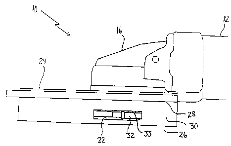
FIGURE 1 is a side elevation view of an apparatus for
installing tongue and groove flooring constructed in accordance
with the teachings of the present invention.
FIGURE 2 is a top plan view of the apparatus for
installing tongue and groove flooring illustrated in FIGURE 1.
FIGURE 3 is a bottom plan view of the apparatus for
installing tongue and groove flooring illustrated in FIGURE 1.
FIGURE 4 is a bottom perspective view of the apparatus for
installing tongue and groove flooring illustrated in FIGURE 1.
FIGURE 5 is a detailed top plan view of a cutting blade
from the apparatus for installing tongue and groove flooring
illustrated in FIGURE 1.
FIGURE 6 is a side elevation view of the apparatus for
installing tongue and groove flooring illustrated in FIGURE 1.
FIGURE 7 is a side elevation view of two boards joined
together by a spline in accordance with the teaching of the
method.
DETAILED DESCRIPTION OF THE PREFERRED EMBODIMENT
The preferred embodiment, an apparatus for installing
tongue and groove flooring generally identified by reference
numeral 10, will now be described with reference to FIGURES 1
through 7.
'. CA 02364641 2001-12-06
4
Structure and Relationship of Parts:
Referring to FIGURE 1, there is provided an apparatus 10
for installing tongue and groove flooring which includes a
handle 12 with a gripping end 14 and an attachment end 16. A
drive motor 18 disposed within handle 12. A switch 20 is
provided on handle 12 for activating drive motor 18. Referring
to FIGURES 1 and 3, an output shaft 22 extends perpendicular
to handle 12 at attachment end 16. A cutting guide 24 overlies
output shaft 22. Referring to FIGURE 1, cutting guide 24 has
a planar first step 26, a planar second step 28 and a riser 30
that extends perpendicularly between first step 26 and second
step 28.
A cutting blade 32 is rotatably mounted on output shaft
22 and projects from riser 30 parallel to and in an
intermediate position between first step 26 and second step 28.
It is sometimes necessary to adjust of the positioning of
cutting blade 32 between first step 26 and second step 28 in
order to accommodate di f f erences in boards 3 6 originat ing f rom
different manufacturers. Referring to FIGURE 6, such
adjustments are accomplished by the addition of shim washers
33 to adjust the positioning of cutting blade 32. Referring
to FIGURE 4, cutting blade 32 is adapted to cut a groove 34 of
a selected depth and width in a board 36. Referring to FIGURE
5, in the illustrated embodiment, cutting blade 32 has a
central aperture 38 for receiving output shaft 22, and a
plurality of cutting edges 40. Referring to FIGURE 4, an
opening 42 is provided in first step 26 to allow access to
cutting blade 32 in order to clear out accumulated debris.
Referring to FIGURE 6, it is preferred that the length of riser
30 be sufficient to provide an aligning edge which assists in
feeding board 36 into cutting blade 32. The shorter the length
of riser 30 leading into cutting blade 32, the more difficult
it becomes to feed board 36 as cutting blade 32 will tend to
"kick back" board 36.
Operation:
'. CA 02364641 2001-12-06
The use and operation of apparatus 10 in accordance with
the preferred method for installing tongue and groove flooring
will now be described with reference to FIGURES 1 through 7.
Referring to FIGURE 1, apparatus 10 as described above, is
5 provided during installation or when effecting repairs for
placing grooves 34 in boards 36 that are resting on a stable
surface such as a floor 44 or boards 36 which have already been
secured down to form part of a floor 44. To do so, first step
26 of cutting guide 24 is positioned against floor 44 with
board 36 positioned between floor 44 and second step 28 of
cutting guide 24. Referring to FIGURES 4 and 6 switch 20 is
used to activate apparatus 10 and cutting guide 24 is then
moved along board 36 to cause cutting blade 32 to cut groove
34 in board 36. The operation is performed with one hand
holding board 36 in position and the other hand controlling
apparatus 10. Referring to FIGURE 4, apparatus 10 is also
capable of putting groove 34 in board 36 where board 36 has
been cut at an angle to fit unusual installation
conf igurations .
Referring to FIGURE 7, for the purpose of this
description, two boards 36 are provided which are labelled as
first board 36a and second board 36b. Most boards have a
mating components which include a tongue 46 and groove 34.
Using apparatus 10 boards can be joined which have neither a
tongue or a groove. A, first groove 34a is cut into first board
36a and a second groove 34b is cut into second board 36b. First
board 36a and second board 36b are then joined by inserting a
spline 48 into first groove 34a and second groove 34b.
Referring to FIGURE 4, during cutting of grooves 34,
accumulated debris may interfere with operation of cutting
blade 32. Opening 42 in first step 26 allows for the removal
of accumulated debris.
Through the use of the method and apparatus described
above practically every board in a tongue and groove floor can
be effectively interlocked against vertical movement.
' CA 02364641 2001-12-06
6
In this patent document, the word "comprising" is used in
its non-limiting sense to mean that items following the word
are included, but items not specifically mentioned are not
excluded. A reference to an element by the indefinite article
"a" does not exclude the possibility that more than one of the
element is present, unless the context clearly requires that
there be one and only one of the elements.
It will be apparent to one skilled in the art that
modifications may be made to the illustrated embodiment without
departing from the spirit and scope of the invention as
hereinafter defined in the Claims.