Note: Descriptions are shown in the official language in which they were submitted.
CA 02364799 2008-02-11
76452-26
CELESTIAL OBJECT LOCATION DEVICE
BACKGROUND - Field of Invention
This invention relates to astronomy, specifically to an electronic device
capable of
locating and identifying celestial objects.
BACKGROUND - Description of Prior Art
People have always been fascinated with the heavens. They have been cited for
the
origins of the universe and life. Stars and constellations are the basis of
fables, myths, and stories
in almost every culture on the earth. The stars are used as indicators of
peoples' future by some.
Sailors and other travelers rely on certain stars and constellations as
indicators of position and
direction. Further, there is an enormous amount of professional and hobbyist
interest in the stars.
Both professionals and hobbyists use celestial object identifying devices to
locate a star,
constellation, planet, comet, asteroid, artificial satellite, deep sky object
or other heavenly
objects, which shallbe referred to collectively as celestial objects. Some
existing celestial object
identifying devices' function by using a combination of inechanical electrical
or pre-tabulated
charts or tables.
U.S. Patent 3,863,365 to Moliard discloses a method which uses a flat spinning
disc that
contains a pictorial representation of a celestial hemisphere containing
constellations and stars.
The user must rotate the disc to the current time and date, and then orient
themselves with the
proper compass direction. Identification of a celestial object is attempted by
the user comparing
the sky with the celestial hemisphere pictorial representation. This method
proves rather difficult
to locate a celestial object, in that the sky and the pictorial representation
of the celestial
hemisphere are two different scales. Additionally, the disc contains a
flattened perspective of the
celestial hemisphere making it difficult to judge at what angle of declination
one would locate
1
CA 02364799 2001-08-27
WO 00/51886 PCT/US00/05330
the desired celestial object. Fprther, the sky contains many more celestial
objects than the
pictorial representation can possibly contain, making it difficult to
determine which pattern of
stars on the pictorial representation corresponds to a particular region of
the sky.
U.S. Patent 5,704,653 to Lee discloses a pictoria; represeniatiorY of the
celestial
hemisphere in which is incorporated an electronic compass. The electronic
compass identifies
which region ofthe sky the operator of the Lee device is facing. The compass
assists in pointing
to the approximate azimuth of the celestial object. However, the task of
determining the proper
declination, and perfornung a mental translation from a set of maps, to the
particular region of
the sky one is observing, is still handled unaided by the operator. This
leaves most of the work
in locating a celestial object to the operator.
U.S. Patent 4,938,697 to Mayer contains a somewhat clumsy and complicated
mechanical method of directly observing a region of the sky without a map. It
requires a good
deal ofunderstanding ofthe devices workings to obtain any success, in addition
it can only locate
a star-group or constellation.
U.S. Patent 4,970,793 to Atamian contains a method for location of stars and
constellations, yet it requires manual alignment of a sphere oriented with the
sky to worle
properly. It also has the same scale difference problem mentioned above that
Patent 3,863,365
that leaves much ambiguity in observing heavenly bodies.
Thus, there is a need for a more user friendly device to locate celestial
objects.
SUMMARY OF THE INVENTION
An improved celestial object locating device has been discovered. In an aspect
of the
invention, a device allows a user to point the device at a celestial object
and the device
announces to the user of the celestial object's identity. In another aspect of
the invention, the
user directs the device to find a desired celestial object. This is done
through a view port and
the instrument detects the geographical location of the user, the time, and
the azimuth and nadir
of the direction of the view port automatically, resulting in a simple to use
celestial object
location device. Other embodiments of the invention comprise combinations of
the above
aspects. These aspects of the invention eliminate the disadvantages of the
prior art concerning
scale and translation from a celestial map. Further, in an aspect of the
invention, the device is
2
CA 02364799 2001-08-27
WO 00/51886 PCTIUSOO/05330
hand-held or attached to a computational device such that the device is
portable.
In an aspect of the invention, a celestial object location (COL) device for
viewing from
a location at a time and a date comprises a viewing means, a processor, a 3-
axis magnetic sensor,
a 3-axis gravitational sensor, a locaticnt ;cans, a- time means, and a
database. The viewing
means assists a user of the COL device in observing along a viewing axis
defined by an azimuth
angle and a nadir angle. The 3-axis magnetic sensor is adapted to provide the
processor witlr
azimuth data representing the azimuth angle. The 3-axis gravitational sensor
is adapted to
provide the processor with nadir data representing the nadir angle. The
locations means provides
location data representing the location to the processor. The time means
provides time and date
data representing the time and date to the processor. The database is adapted
to be accessed by
the processor and provide data such that the processor determines celestial
coordinates of right
ascension and declination corresponding to the viewing axis based on the
azimuth data, the nadir
data, the location data, and the time and date data.
In a further aspect of the invention, the viewing means comprises a viewing
channel
adapted to enable a user to observe through the device along the viewing axis.
In a further aspect of the invention, there is a direction indicator adapted
to announce
directions to change the angular orientation viewing axis, wherein the
direction indicator is
further adapted to be controlled by the processor and comprises a visual
indicator, an auditory
indicator, or a tactile indicator.
In a still further aspect ofthe invention, the direction indicator is adapted
to be controlled
by the processor, comprises an illuminate-able visual display that is viewable
by the user when
the user is observing through the viewing channel, and is adapted to
illuminate at least a portion
of the visual display such that a user changes the viewing axis based on the
illuminated visual
display. The visual display may be a circularly arranged series of illuminate-
able arrows, wherein
the processor and the arrows are adapted such that the processor directs a
least a portion of the
arrows to be illuminated.
In an aspect of the invention, a reticule is present and adapted to be
viewable by the user
when the user is observing through the viewing channel.
In an aspect of the invention, the viewing means comprises a display screen
adapted to
display an image observed along the viewing axis. Further, there may be a
direction indicator
adapted to announce directions to change the angular orientation viewing axis,
wherein the
3
CA 02364799 2001-08-27
WO 00/51886 PCT/US00/05330
direction indicator is further adapted to be controlled by the processor and
comprises a visual
indicator, an auditory indicator, or a tactile indicator.
In an aspect of the invention, the device comprises a housing and wherein the
viewing
mea.ris `omprisc:;;..a.Y-lewing channel extending through-the housing and
adapted to permit a user
to observe through the viewing channel along the viewing axis. In a further
aspect of the
invention, the processor is spaced apart from the housing. In an additional
aspect of the
invention, the housing is adapted to be held by the user while the user is
observing through the
viewing channel.
In a further aspect of the invention, the COL device comprises a direction
indicator
adapted to announce directions to change the angular orientation of the
viewing axis, wherein
the direction indication is further adapted to be controlled by the processor
and comprises a
visual indicator, an auditory indicator, or a tactile indicator. This COL
device may further
comprise a user interface adapted for the user to input an identification of a
celestial object or
celestial coordinates to the processor. Additionally, the processor and the
database is adapted
such that the processor directs the user via the direction indicator to change
the angular
orientation of the viewing axis such that the viewing axis is aligned with the
celestial object or.
the celestial coordinates, wherein the database comprises data associating the
identification of
the celestial object with the celestial object's celestial coordinates.
In still further aspects of the invention, the processor is adapted to
announce to the user
via the direction indicator that the viewing axis is aligned with the
celestial object or the celestial
coordinates. Additionally, the user interface may be adapted for the user to
input an
identification of a celestial object comprising multiple celestial
coordinates. In this case, the
processor and the database is adapted such that the processor directs the user
via the direction
indicator to change the angular orientation of the viewing axis such that the
viewing axis is
serially aligned with the multiple celestial coordinates of the celestial
object, thereby the user is
provided with a tour of the celestial object. In a still further aspect of the
invention, the user
interface is adapted for the user to input a signal to the processor to direct
the user via the
direction indicator to change the angular orientation of the viewing axis from
a current celestial
coordinate to a next multiple celestial coordinate.
In a further aspect of the invention, there is a user interface adapted for
the user to signal
to the processor to identify a celestial object or celestial coordinates
aligned with the viewing
4
CA 02364799 2001-08-27
WO 00/51886 PCTIUSOO/05330
axis, wherein the database is adapted for the processor to access the database
for data related
to the celestial object or the celestial coordinates. The user interface is
further adapted to
announce to the user the celestial object or the celestial coordinates. In a
still further aspect of
the invention, the user interface is adapted for the user to signc,l to the
proccssor through
activating a manual switch or through an auditory command, and for the
processor to announce
to the user through a visual display or a speaker.
In a further aspect of the invention, the database is adapted to be changed by
the user
editing the database through a user interface of the device in functional
communication with the
processor, a plug-in module adapted to be in functional communication with the
processor, or
an information transfer system adapted to be in functional communication with
the processor.
In an aspect of the invention, the location means comprises a user interface
adapted for
the user to input location information to the processor, wherein the database
is adapted to
provide the processor with the location data based on the inputted location
inforrnation.
In an aspect of the invention, the time means comprises a time keeping device
adapted
to provide the time and date data to the processor.
In an aspect of the invention, the location means and the time means comprises
a global
positioning device adapted to provide the location data and the time and date
data to the
processor.
In an aspect of the invention, there is an output device for announcing the
elevation angle
of the viewing axis, wherein the elevation angle is nadir angle minus 90
degrees.
In an aspect of the invention, there is an output device for announcing a
compass heading
as a function of the azimuth angle and the nadir angle.
In an aspect of the invention, there are compensation instructions readable by
the
processor and/or compensation data in the data base such that the processor
compensates for
procession, earth elongation, magnetic variation, parallax, nutation, or a
combination thereof.
In an aspect of the invention, there is a temperature sensor adapted to
interface with and
enable the processor to make thermal error compensations of the magnetic and
gravitational
sensors.
In an aspect of the invention, the database contains additional data
representing when a
celestial object is visible to a naked eye at the location, the device further
comprises an
announcement device functionally connected to the processor, and the processor
is adapted to
5
CA 02364799 2001-08-27
WO 00/51886 PCTIUSOO/05330
announce through the announcement device the additional data representing when
the celestial
object is visible to a user at the location.
In an aspect of the invention, there is a celestial object location device for
use from a
location at a time and a date comprisi::g:
a. a housing comprising a viewing channel adapted for a user to observe
through
the viewing channel and along a viewing axis to a position in the sky aligned
with the
viewing axis, wherein the housing is adapted to be held by the user while the
user is
observing through the viewing channel;
b. a processor;
c. a 3-axis magnetic sensor adapted to provide the processor with azimuth data
representing an azimuth angle of the viewing axis;
d. a 3-axis gravitational sensor adapted to provide the processor with nadir
data
representing a nadir angle of the viewing axis;
e. a location data input device adapted to provide the processor with location
data
representing the location of the celestial object location device;
f. a time data input device adapted to provide the processor with time and
date data
representing the time and date of a use of the device;
g. a user interface for inputting user data to the processor and announcing
information to the user;
h. a direction indicator adapted for the processor to announce through the
direction
indicator to the user directions for changing the angular orientation of the
viewing axis;
and
i. a database adapted to be accessed by the processor such that the processor,
based
on the azimuth data, the nadir angle, the location data, the time and date
data, the user
data, and the database, announces to the user:
i) through the user interface an identification of a celestial object aligned
with the viewing axis;
ii) through the user interface celestial coordinates aligned with the viewing
axis; or
iii) through the direction indicator directions for the user to change the
viewing axis based on user data comprising identification of a celestial
object or
6
CA 02364799 2001-08-27
WO 00/51886 PCT/US00/05330
a celestial coordinate.
In an further aspect of the invention, the processor is spaced apart from the
housing.
In a further aspect ofthe invention, the direction indicator comprises a
circularly arranged
series of il:;:munat; : able arrows that are in functional communication with
the processor, the
arrows being adapted such that illuminated arrows are visible by the user
observing through the
viewing channel, and the direction indicator and the processor are adapted to
illuminate at least
a portion ofthe arrows such that a user changes the angular orientation ofthe
viewing axis based
on the illuminated portion of the arrows.
In a further aspect of the invention, the database is adapted to be changed by
the user
editing the database through the user interface, a plug-in module adapted to
be in functional
communication with the processor, or an information transfer system adapted to
be in functional
communication with the processor.
In an aspect ofthe invention, thereis a process for observing celestial
objects comprising
the steps of:
a. providing a user with a device for observing the celestial objects along a
viewing
axis;
b. identifying an azimuth angle of the viewing axis via a 3-axis magnetic
sensor
adapted to determine the azimuth angle;
c. identifying a nadir angle of the viewing axis via a 3-axis gravitational
sensor
adapted to determine the nadir angle; and
d. determining celestial coordinates of right ascension and declination based
on the
azimuth angle, the nadir angle, a location of the device, and a current time
and
date.
In a further aspect ofthe invention, the providing step further comprises a
step of holding
the device, the 3-axis magnetic sensor, and the 3-axis gravitational sensor in
a hand of the user.
In a still further aspect of the invention, the 3-axis magnetic sensor and the
3-axis gravitational
sensor are integral to the device.
In a further aspect of the invention, there is a step of directing a processor
to receive data
representing the azimuth angle, the nadir angle, the device location, and the
current time and
date, consult a database, and announce the celestial coordinates via an
announcement device.
In a further aspect of the invention, there is the step of inputting to a
processor an
7
CA 02364799 2001-08-27
WO 00/51886 PCTIUSOO/05330
identification of a desired celestial object wherein the processor is also
directed to perform the
determining the celestial coordinates step. Further, there is a step of
directing the processor to
announce, via a direction indicator, instructions understandable to the user
concerning how to
change the angular orientation of the viewing axis until the desired celestial
object is aligned with
the viewing axis. In a still further aspect of the invention, there is the
step of repeating the
directing the processor to announce step such that the user is instructed to
tour through portions
of the desired celestial object.
In a further aspect of the invention, there is the step of inputting to a
processor a desired
celestial coordinate wherein the processor is also directed to perform the
deternuning the
celestial coordinates step. There is also the step of directing the processor
to announce via a
direction indicator instructions concerning how to change the angular
orientation of the viewing
axis until the desired celestial coordinate is aligned with the viewing axis.
In an aspect of the invention, a process of observing a celestial object
comprises the step
of providing an embodiment of the invention described in this disclosure and
the step of updating
the database with additional data concerning the celestial object such that a
user of the devicc
directs the processor to announce the directions to change the angular
orientation of the viewing
axis such that the viewing axis is aligned with the celestial object via the
direction indicator. In
a further aspect of the invention, the updating step comprises the step of
functionally connecting
a plug-in module comprising the additional data to the device or the step of
downloading the
additional data to the database via an information transfer system. The
downloading step may
comprise the step of accessing the Internet to retrieve the additional data.
Further, accessing
step comprises the step of purchasing the additional data.
Further objects and advantages will become apparent from a consideration of
the
drawings and ensuing description.
BRIEF DESCRIPTION OF THE DRAWINGS
Figure 1 is a schematic perspective view of a user identifying a celestial
object with a
device according to an embodiment of the invention.
Figure 2 is a detail perspective view of the device shown in Figure 1.
Figure 3 is a view through the device shown in Figure 1 while observing a
celestial
8
CA 02364799 2001-08-27
WO 00/51886 PCTIUSOO/05330
object.
Figure 4 is a schematic representation of the components of the device shown
in Figure
1.
Figure 5 is a schematic view of an embodiment of the invention incorporating a
digital
personal assistant.
DESCRIPTION OF THE PREFERRED EMBODIlAENTS
Referring now to the figures, wherein like reference numerals refer to like
elements
throughout the figures, and specifically to Figure 1, a celestial object
location device (COL
device) 10 is being used by a user 12 to locate a celestial object 14. The COL
device 10
according to the shown and a preferred embodiment of the invention, has a
generally cylindrical
housing 16 adapted to be hand-held. Other embodiments of the invention may
have housings
of other shapes and may or may not be hand-held.
The housing 16 of the COL device 10 has a first view port 18 that is held
proximate to
the user 12 and a second view port 20 proximate to the celestial object 14.
During use, the view
ports 18 and 20 are aligned between the user 12 and the celestial object 14
and the COL device
10 is adapted such that the user views the celestial object through the COL
device along a
viewing axis 34.
Other embodiments of the invention may have an optical sensor that is
positioned to view
the celestial object 14 and transmit an image from the optical sensor to a
view screen such that
the user observes the image on the screen (not shown). In further embodiments
of the invention,
the COL device 10 is mounted to a support or a frame and is adapted to be
positioned
mechanically, electronically, pneumatically, or by some other suitable means
other than by direct
manual manipulation (not shown). The positioning of the mounted COL device 10
may be
directed by the user through switches, by a functionally integrated
computational device, or a
combination of both. Still further embodiments of the invention may have the
COL device 10
mounted to a support or a frame and may be positioned through direct manual
manipulation,
thereby providing stability to the device (not shown).
Referring now to Figure 2 as well, the COL device 10 comprises the housing 16,
the view
ports 18 and 20, and a data input/output interface (101) 30, and a viewing
button or switch 32:
9
CA 02364799 2001-08-27
WO 00/51886 PCTIUSOO/05330
A viewing axis 34 is shown extending axially through the cylindrical housing
16. The 10130
is comprised of a display screen 36 for displaying data, such as in the form
of menus and results,
as explained further below. The 10130 also comprises a plurality of buttons or
switches 38 for
inputting data and commands, such as moving through menus on the display
screen 36 and
inputting queries. The viewing switch 32 is positioned and adapted to be
easily activated by the
user's thumb or finger when the user is observing through the COL device 10.
Referring now to Figure 3, the COL device 10 is shown displaying the view the
user has
when the celestial object 14 is aligned with the viewing axis 34 of the device
10. The user 12
is observing the object 14 through a viewing channel 46 that extends through
the COL device
10. The viewing channel 46 is defined by an interior surface 48 of the housing
16 in the shown
embodiment. Further, the viewing channel 46 is bounded by the view ports 18
and 20.
Shown extending from the left side of the housing 16 is the 10130 and shown
extending
from the bottom of the housing is switch 32. Other embodiments of the
invention may have
other configurations of the 10130 and the switch 32.
Referring now to a viewing portion 40 of the COL device 10, a circularly
arranged seriey
of illuminating directional arrows 42 are positioned adjacent to the interior
surface 48 of the
housing 16. The arrows 42 are illuminated as required to direct the
positioning of the COL
device 10 during use. Eight arrows 42 are shown but other embodiments of the
invention may
have more or less arrows. The size, shape, and number of the illuminating
arrows 42 is not
paramount to the function performed. What is paramount is that there is a way
for the COL
device 10 to inform the user 12 of a required change in viewing axis to align
the device with a
particular location in the sky and, therefore, the arrows 42 are direction
indicators. There are
many variations on color and shape of the direction indicators as well. Other
embodiments of the
invention may have other suitable ways for visually informing the user how to
direct the COL
device 10, such as illuminating dots or borders. The illumination of the
arrows 42 may be
accomplished by any suitable means, such as LED or fiber optics. In a
preferred embodiment
of the invention, the arrows are not an overlayed image.
Embodiments of the invention have many variations on the operation of the
arrows 42
or other suitable direction indicators. In embodiments of the invention, the
arrows 42 blink at
different rates, change color, or intensity depending on how far the user 12
has to angularly
change the viewing axis 34. For example, if the user 12 is very close to the
desired viewing axis
CA 02364799 2001-08-27
WO 00/51886 PCT/CJS00/05330
position, the arrow or arrows 42 blink quickly and if the user were further
away the arrow or
arrows 42 may blink slowly. Other embodiments of the invention may use
tactile, such as
vibrational, or auditory means for announcing direction.
In another embodiment of the invention, once the viewing axis 14 is aligned
with thg,
desired celestial object 14, the arrows 42 may all light up or blink. Still
other embodiments of
the invention may have devices that announce visually, tactilely, or
auditorily when the desired
angular position of the COL device 10 is achieved, such as sounding a beep or
syntlhesized voice.
A reticule 44 is centrally positioned in the viewing portion 40. The reticule
44 is helpful
in centering the COL device 10 on the celestial object 14. Other embodiments
of the invention
may have other reticule or cross-hair designs or not have any means for
centering the celestial
object 14. In still other embodiments of the invention, the reticule 44 may be
used to announce
achievement of a desired angular position either by illuminating with more
intensity, ceasing
illumination, or flashing.
Referring now to Figure 4, incorporated into the COL device 10 are a number of
other
components to operate the device as shown in schematic representation 50. In
the shown
embodiment, a processor 52 integrates the components which comprise a 3-axis
magnetic field
sensor 54, a 3-axis gravitational field sensor 56, a time keeping device 58,
input devices 60, a
celestial object database 62, illuminating arrows 64, and a display 66, which
are arranged in a
counterclockwise fashion starting at the top left corner of Figure 4. In a
preferred embodiment
of the invention, the components are incorporated into the housing 16 of the
COL device 10.
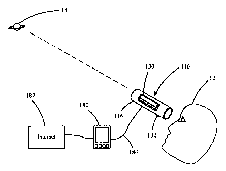
Referring now to Figure 5 as well, in other embodiments of the invention, a
COL device
110 may comprise a portion external to the housing 116 comprising one or more
of the
components, such as the processor 52 and/or the database 62 residing in an
auxiliary device 180
that is in functional communication with the remainder of the components.
Examples of suitable
auxiliary devices include a personal digital assistant, a desk top computer,
or a lap top computer,
however, embodiments of the invention are not limited to these examples.
Therefore, in
embodiments of the invention, the processor is spaced apart from the housing.
Other
embodiments of the invention incorporate the time keeping device 58, the input
devices 60,
and/or the display 66 into the auxiliary device 180. Still other embodiments
of the invention have
multiple auxiliary devices. It is understood that the term "auxiliary device"
in the below claims
is to be interpreted as encompassing one or more auxiliary devices.
11
CA 02364799 2001-08-27
WO 00/51886 PCT/US00/05330
In another embodiment ofthe invention, the configuration ofthe COL device 10
may not
require the 101130 or the switch 132 and the input and output of data may be
accomplished by'
the auxiliary device 180. In another embodiment of the invention, the database
62 may be
communicated to through an information tra:.sfer system, such as a network
system, connection
to another database, or via the Internet 182. The components in the housing 16
and the auxiliary
device 180 may be in functional communication through a physical conduit 184
capable of data
transfer, such as electrical or optical signal transfer media, or via a
process not requiring a
physical conduit, such as processes utilizing infrared or RF technology, for
example.
Referring back to Figure 4, input devices 60 enable the user to input data
into the
processor 52. In the embodiment of the invention shown in Figure 1, the input
devices 60
correspond to the 101 switches 38 and the switch 32. Other embodiments of the
invention may
have data input devices of any suitable type, such as auditory for example, or
the data input
devices may be incorporated into the auxiliary device 180.
The processor 52 is in communication with the celestial object database 62 in
order to
retrieve information about celestial objects therefrom. The information in the
databases of the
embodiments of the invention may differ, but those skilled in the art
understand the variety ot
information that may be in the database. The database 62 may also contain
retrievable data for
any other suitable purpose, such as linking a geographical location with a
latitude and a longitude
coordinate.
The processor 52 analyzes the input from the sensors 54 and 56, the
timekeeping device
58, the input device 60, communicates with the database 62 as required, and
outputs information
through the arrows 64 and the display 66, which corresponds to the 101 display
36 of the
embodiment shown in Figure 1.
The processor 52 receives information from the magnetic field sensor 54 and
the
gravitational field sensor 56 in order to calculate the direction or vector
that the COL device 10
is pointing. The vector is a three dimensional vector relative to the azimuth
angle and the nadir
angle of the COL device 10. The azimuth angle is the angle between magnetic
north and the
device pointing direction. The nadir angle is the angle between straight down
into the earth and
the device pointing direction. The azimuth vector is determined using the
magnetic field sensof
54 and the nadir angle is determined using the gravitational field sensor 56.
The information from
the sensors is processed by the processor 52 using means commonly known by
those skilled in
12
CA 02364799 2008-02-11
76452-26
the art.
The use of a 3-axis gravitational sensor 56 is required to determine the
position of the
nadir angle. The nadir angle is the three dimensional angle between two
particular vectors. The
first vector is.in thP.dirPc#_ion which the viewing axis 34 is pointed. The
second vector is pointing
straight into the ground, towards the center of mass of the earth. In a
preferred embodirrient of
the invention, the 3-axis gravitational sensor will employ a minimum of three
individual
accelerometers to determine the 3-axis gravitational field vector, although
other embodiments
of the invention may use devices other accelerometers. The accelerometers used
must be capable
of sensing a static force, in this case the earth's gravitational force of 1
g. These types of
accelerometers are readily available devices offering ample precision to
perform this function.
In an embodiment of the invention, the three individual accelerometers are
oriented orthogonally,
90 degrees from each other in the X, Y, and Z.planes. Through common geometric
calculations
the individual readings from the three accelerometers can be combined to yield
the nadir angle.
Without at least three accelerometers in the 3-axis. gravitational sensor 56,
in
contradistinction to U.S. Patent No. 5,311,203 to Norton which discloses the
use of only one inclinometer, there can be
large errors in the accuracy of the COL device 10. These errors would be
dependant on what
angle the user 12 held the COL device 10 and how they,oriented the `roll' axis
of the device.
In a device which only uses the earth's magnetic field, and the earth's
gravitational field is use&
to sense orientation, the only way to avoid these errors is by using 3-axis
sensors for measuring
the magnetic field and the gravitational field. These errors cannot be ignored
as they may easily
be larger than one field of view which would render the COL device 10 useless.
Once theodirection vector of the COL device 10 is determined, the processor 52
uses
longitude, latitude, local'time and date data of the COL device 10 to perform
a translation of the
device direction vector into celestial coordinates. In an embodiment of the
invention, the
longitude and latitude. data is manually input by the user via the input
devices 60. The longitude
and latitude may be in the form of coordinates, but may also may be indirectly
input by the user
12 entering another geographical indicator into the COL device 10, such as a
town, county, zip
code, portion of a state, state, or region of the county, in which case the
database 62 or another
database contains the information to assist in determining the longitude and
latitude of the device
10. The local time and date may be inputted manually as well, but in a
preferred embodiment
of the invention, the time keeping device 58 inputs this information to the
processor 52.
13
CA 02364799 2001-08-27
WO 00/51886 PCTIUSOO/05330
In another embodiment ofthe invention, the COL device 10 includes a global
positioning
system receiver (not shown) or any other suitable device for automatically
inputting the
longitude, latitude, time and date information, or portions thereof, to the
processor 52.
The processor takes the direction vector information received fr^rr~ the
sensprs, 54 and
56, the time and date information from the time keeping device 58, and the
information from the
user via the input devices 60. This information is used by the processor 52 to
perform a search
against the database to determine the celestial coordinates of right ascension
and declination to
which the viewing axis 34 is pointing. Embodiments of the invention have one
or numerous
functions to perform at this point, as discussed below.
Identification of a Celestial Object.
Referring now to all the figures, the user 12 points the COL device 10 to a
celestial
object 14 whose identification is desired. More specifically, the user aligns
the center of the
viewing portion 40 with the celestial object 14, such that the viewing axis 34
is aligned with the
object 14. The user activates the switch 32 to input to the processor 52 that
the object 14 has
been located. The processor 52 then receives the data from the sensors 54 and
56, the time and
location data, consults the database 62, and displays on the screen 36 the
information about the
celestial object 14.
Location of a Celestial Object
Another common mode of operation that the COL device 10 supports is to help
the user
12 locate the celestial object 14 in the sky. For example, if the user 12
wants to know where
Saturn is currently located they would use the "locate" mode. To locate the
desired celestial
object, the operator selects Saturn from a list of available objects via the
10130. Then, the user
12 views through the COL device 10. The processor 52 directs the user to
change the
orientation of the COL device via the illumination of the arrows 42. For
example, if the viewing,
axis 34 needs to be oriented more vertically and to the left, the arrows 42 in
the upper left
quadrant of the view portion 40 will light up. Once the desired celestial
object, Saturn, is aligned
with the viewing axis 34, all of the arrows 42 will not be illuminated, may
blink, or the device
14
CA 02364799 2001-08-27
WO 00/51886 PCT/US00/05330
may utilize another suitable device for announcing to the user 12 that
alignment has occurred.
In an embodiment of the invention, the COL device 10 may track the ecliptic
for the user.
An example of an ecliptic is the plane of the earth's orbit as it forms an
imaginary arc across the
sky during rotation about the sun. This arc can be tr aced using the
illuminated arrows 42 as a
guide. Further embodiments of the invention may track paths of other celestial
objects, such as
comets and satellites.
Tours of Constellations and Sky Tours
Since many constellations cover large areas of the sky and include multiple
stars, an
embodiment of the COL device 10 gives a tour of the constellation. In an
embodiment of the
invention, the constellation is chosen and input through the 1013 0. The COL
device 10, through
the arrows 42 directs the user 12 to align the viewing axis 34 with the
brightest star in the
constellation. Once the alignment is achieved and the COL device 10 indicates
it, the user
activates the switch 32, and COL device directs the user to the next brightest
star in the
constellation. This process continues until the stars of the constellation
have all been aligned
with the viewing axis 34 in a serial fashion, from a cunent celestial
coordinate associated with
a current celestial object to a next celestial coordinate associated with a
next celestial object.
Similarly, sky tours of celestial objects may also be included in an
embodiment of the invention,
such as a sky tour of the Zodiac constellations.
Other Modes of Operation
Embodiments of the invention may have several other modes of operation which
are
possible based on the instrumentation in the COL device 10. The COL device 10
may function
as a digital compass and display the compass heading. In an embodiment of the
invention, the
COL device 10 uses both the azimuth and nadir data to compensate for when the
COL device
is not held parallel to the ground.
The COL device 10 may function as an elevation angle instrument, and display
the
elevation angle. The COL device 10 may display the celestial coordinates to
which it is pointed.
This last mode of operation is useful for an astronomer who has the celestial
coordinates of ar,
CA 02364799 2001-08-27
WO 00/51886 PCTIUSOO/05330
object (from a table or chart) which is not already in the device's database.
The COL device 10
may display the date and time in various time standards including local, UT or
GMT times.
In other embodiments of the invention, the COL device 10 may perform a series
of
compensations to improve the accuracy of the instrument. These include but are
not limited to:
procession (earth axis wobble), earth elongation (earth not completely
circular), magnetic
variation (difference between true north pole and magnetic north pole),
parallax (error in celestial
coordinates due to earth orbit), and nutation (earth axis "nodding" on
processional circle).
Embodiments of the invention may include a temperature sensor for thermal
error compensation
of the magnetic and gravitational sensor arrays. The processor may compensate
for unstable
shaky hands of the operator in some embodiments of the invention.
An embodiment of the device may enable the database 62 to be updated with new
information concerning celestial objects and the current magnetic pole
location. This would be
particularly useful for tracking artificial satellites where orbital elements
can change based on
mission requirements, for example, the Mir space station, the International
Space Station, and
the Hubble Space Telescope. This would also be useful for newly launched
artificial satellites
placed in orbit after the unit is in the field. For example, the Space
Shuttle. This would also be
useful for newly discovered celestial objects like comets and asteroids.
Adding information
about these celestial objects to the database may be accomplished by user
entry, through an
expansion chip or another type of plug-in module, or electronically, for
example downloading
from another computer through direct connection, over a telephone line, or via
another type of
information transfer system, such as a network or the Internet. For example, a
modem port
would allow the device to plug into the phone system, call a number, and
update the database
and magnetic north pole position online after the device was fielded.
Other embodiments of the invention, the COL device 10 would either come with
astronomy tutorials in the database 62, in another database (not shown), in a
plug-in module,
downloadable from another computer either directly, over the telephone lines,
or via another type
of information transfer system, such as a network or the Internet. In a
similar fashion,
downloadable constellation tours and sky tours may also be available in some
embodiments of
the invention.
In another embodiment of the invention, the COL device 10 could include
calculations
well known to those skilled in the art for notifying the operator of the next
naked eye viewing
16
CA 02364799 2001-08-27
WO 00/51886 PCTIUSOO/05330
opportunity for artificial satellites. For example the user could choose the
International Space
Station, then the COL device 10 could inform them of the next time the
International Space
Station would be visible with the naked eye.
In another embodiment of the invention, the COL device 10 may :r_c_!:;de a
reflPx viPwer
which would superimpose an illuminated reticule and direction indicators in
the viewing area,
allowing for the user 12 to hold the device further out from the eye. This
would also prevent the
user from observing through the viewing channel 46 too far off parallel to the
viewing axis 34.
The COL device 10 is not limited to being of a hand-held size and there are
many
possible interpretations of hand-held size. In addition the COL device 10 may
function on a
much larger or smaller scale so the scope of the embodiments of the invention
should not be
limited to that of a hand-held size.
In alternative embodiments of the invention, the COL device 10 may have other
inputJoutput devices, other switches, other locations thereof, and many
variations thereof, for
example in number, arrangement, size, and type, including options wherein
there are no
input/output devices or switches on the housing 16.
In another embodiment of the invention, a viewer or reflex viewer could be
located
outside the housing 16 in such a manner so as the user 12 may still sight
parallel to the viewing
axis.
While the above description contains many specifics, these should not be
construed as
limitations on the scope of the device, but rather as an exemplification of
one preferred
embodiment thereof. Many other variations are possible.
17