Note: Descriptions are shown in the official language in which they were submitted.
CA 02364986 2001-12-13
Adaptive Generalized Matched Filter Rake Receiver System And Method
BACKGROUND
1. FIELD OF THE INVENTION
This invention relates generally to the field of spread spectrum rake
receivers. More
particularly, an Adaptive Generalized Matched Filter rake receiver system and
method is
provided that is especially well suited for use in a mobile communication
device.
2. DESCRIPTION OF THE RELATED ART
Mobile communication devices operate in a multi-path propagation environment,
i.e.,
there is typically more than one propagation path from the transmitter to the
receiver. In
addition, the velocity of the mobile device may vary from 0 km/h (standing
still) to 500 km/h
(traveling in a high speed train). Therefore, the multi-path propagation
environment will
typically range from direct line of sight to multi-clustered, multi-path
propagation with no
direct line of sight spread over several microseconds. Consequently, typical
mobile
communication devices employ a multi-fingered rake receiver that uses simple
Maximal
Ratio Combining and standard pilot tracking processing in order to track the
centroids of the
multi-path clusters in a spread spectrum signal, such as a Code Division
Multiple Access
(CDMA) signal.
A typical Maximal Ratio Combining (MRC) rake receiver includes a plurality of
fingers, each of which correlates to a different delay of an input signal. The
correlator
outputs from each finger are then typically weighted by a vector of complex
weighting
coefficients, and combined to form a decision variable. In typical MRC rake
receivers, the
values of the coefficients in the weighting vector are chosen without regard
to the statistical
correlation properties of the noise impairment in the received signal, for
instance by setting
each weighting coefficient as the complex conjugate of the channel impulse
response. As a
1
CA 02364986 2006-03-23
result, typical MRC rake receivers perform optimally when the noice corruption
to the
input signal is limited to Independent Additive Noise (IAN), such as Additive
White
Gaussian Noise (AWGN), which is independent of the signal transmitted to the
mobile
device from a base station. In typical mobile communication systems, however,
multiple
spread spectrum signals are transmitted at a single bandwidth, resulting in
dependent
noise, such as Multi-User Interface (MUI). Because typical MRC rake receivers
are
optimized to compensate for IAN, they are often sub-optimal when dependent
noise is
present.
The use of a Generalized Matched Filter (GMF) to compensate for dependent
noise
in a spread spectrum signal is known. For instance, a generic description of a
GMF is
found in Kay, "Fundamentals of statistical signal processing - detection
theory, "Prentice
Hall, 1998. In addition, the user of a GMF in a CDMA receiver is disclosed in
G.
Bottomly et al, "A generalized Rake receiver for interference suppression,"
IEEE Journal
on selected areas in communications, Vol. 18, No. 8, Aug. 2000. Known
Generalized
Matched Filters, however, require an excessive amount of processing, and are
therefore
not typically implemented in mobile communication devices.
SUMMARY
An adaptive Generalized Matched Filter (AGMF) rake receiver system includes a
rake receiver and an ADMF weight determination module. The rake receiver is
coupled to
a spread spectrum input signal and applies a vector or weight signals to the
spread
spectrum input signal to compensate for dependent noise and to generate a
decision
variable. The AGMF weigh determination module monitors the decision variable
and
generates the vector of weight signals, wherein optimal values for the vector
of weight
signals are calculated by the AGMF weight determination module by varying the
vector of
weight signals until the signal to noise ratio of the decision variable
reaches a peak value.
In one aspect of the invention, there is provided an Adaptive Generalized
Matched
Filter (AGMF) rake receiver system, comprising a rake receiver coupled to a
spread
spectrum input signal that applies a vector of weight signals (*) to the
spread spectrum
input signal to compensate for dependant noise and generates a decision
variable; and an
AGMF weight determination module that monitors the decision variable and
generates the
2
CA 02364986 2006-03-23
vector of weight signals (w) , wherein optimal values for the vector of weight
signals (w)
are calculated by the AGMF weight determination module by varying the vector
of weight
signals (w) until a signal-to-noise ratio of the decision variable reaches a
peak value;
wherein the AGMF weight determination module monitors two consecutive states
of the
decision variable in order to determine when the signal-to-noise ratio of the
decision
variable is at the peak value; wherein the AGMF weight determination module
simultaneously generates a first (w(q)) and a second (w(q')) vector of weight
signals, each
vector of weight signals corresponding respectively to one of the two
consecutive states of
the decision variable, and wherein the rake receiver comprises a plurality of
correlator
fingers that receive the spread spectrum input signal and apply a despreading
signal to
generate a plurality of correlation output signals; a first output stage that
applies the first
vector of weight signals to the plurality of correlation output signals and
generates a first
consecutive state of the decision variable; and a second output stage that
applies the
second vector of weight signals to the plurality of correlation output signals
and generates
a second consecutive state of the decision variable.
In another aspect, there is provided a method of optimizing a signal-to-noise
ratio
in a decision variable output of an Adaptive Generalized Matched Filter (AGMF)
rake
receiver system, comprising the steps of providing a rake receiver that
applies a vector of
weight signals (w) to a spread spectrum input signal to compensate for multi.-
user
interference and generates a decision variable output; providing a Code
Division Multiple
Access (CDMA) processing module that monitors the decision variable output and
generates the vector of weight signals as a function of a scalar parameter
(ro); setting the
scalar parameter to a first value; generating a first vector of weight signals
(w(q)) using
the first scalar parameter value; generating a first decision variable output
using the
CDMA processing module according to the first vector of weight signals (w(q))
;
calculating a first signal-to-noise ratio of the first decision variable
output; setting the
scalar parameter to a second value; generating a second vector of weight
signals
(tiv(q')) using the second scalar parameter value; generating a second
decision variable
output using the CDMA processing module according to the second vector of
weight
signals (w(q' )) ; calculating a second signal-to-noise ratio of the second
decision variable
2a
CA 02364986 2006-03-23
output; and if the second signal-to-noise ratio is greater than the first
signal-to-noise ratio,
then setting the first scalar parameter value to the second scalar parameter
value.
In yet a further aspect, there is provided a method of determining a vector of
weight signals (w) for optimizing a spread spectrum signal rake receiver in a
mobile
communication device, comprising the steps of receiving a spread spectrum
signal;
detenmining a vector of channel impulse response signals (h) from the spread
spectrum
signal; providing an independent noise covariance matrix (R'a") stored in a
memory
location on the mobile communication device; monitoring the vector of channel
impulse
response signals (h) to determine a dependent noise covariance matrix (Rmu-) ;
determining a total noise covariance matrix (Ru) as a function of the
independent noise
covariance matrix 'R'A"), the dependent noise covariance matrix (R"u') and a
scalar
parameter (ro); and determining the vector of weight signals (w) from the
total noise
covariance matrix (R ) and the vector of channel impulse response signals (h)
.
2b
CA 02364986 2001-12-13
BRIEF DESCRIPTION OF THE DRAWINGS
Fig. 1 is a block diagram of an exemplary rake receiver for use in an Adaptive
Generalized Matched Filter (AGMF) rake receiver system;
Fig. 2 is a block diagram of an exemplary AGMF rake receiver system;
Fig. 3 is a graph plotting exemplary multi-path components { hl, h2, ..., hJ }
of the
channel impulse response h as a function of time;
Fig. 4 is a more detailed block diagram of the AGMF Weight Determination
module
shown in Fig. 2;
Fig. 5 is a graph plotting the SNR of the decision variable output z from the
rake
receiver as a function of the scalar parameter ro;
Fig. 6 is a block diagram of an exemplary Dual Decision Statistic Pilot Rake
Receiver; and
Fig. 7 is a flow diagram illustrating an exemplary method for calculating the
optimal
weight signal vector *opt.
DETAILED DESCRIPTION
Referring now to the drawing figures, Fig. 1 is a block diagram of an
exemplary rake
receiver 10 for use in an Adaptive Generalized Matched Filter (AGMF) rake
receiver system.
The rake receiver 10 includes a plurality of correlator fingers 12, a
plurality of weight
multipliers 14, and an adder 16. Each correlator finger 12 includes a delay
element 18, a
multiplier 20 and an integrator 22. Also shown is a receiver chain impulse
response block 24,
a pulse shaping filter 26 and a coded sequence co(n) block 28.
A multi-path, spread spectrum signal x(t), such as a CDMA signal, is received
by the
mobile communication device, and is filtered by the receiver chain impulse
response block
3
CA 02364986 2001-12-13
h,,(t) 24 to generate a demodulated base-band input signal r(t) to the rake
receiver 10. The
receiver chain impulse response block h,.(t) 24 represents the combined filter
responses in the
receiver chain prior to the rake receiver 10, such as the responses from an RF
filter, band
limiting components, an IF filter, and DSP filtering blocks. The input signal
r(t) to the rake
receiver 10 is coupled to one input of the multiplier 20 in each correlator
finger 12.
Each correlator finger 12 also receives a despreading signal c(t), which is
formed by
convolving the coded sequence co(n) 28 for the desired traffic channel (n is
the chip index)
with the impulse response hP(t) of the pulse shaping filter 26. The impulse
response hp(t)
may be a single impulse or a rectangular pulse, depending upon how the
correlation function
is implemented. Each correlator finger 12 is represented with an index number
1,2,,...11.
Operationally, each correlator finger 12 is substantially the same as the
first, which will be
described next in greater detail. A delay element (dl) 18 is then applied to
the despreading
signal c(t) within each correlation finger 12 in order to generate a shifted
despreading signal
c(t-dl) that is aligned with one channel of the multi-path input signal r(t).
The shifted
despreading signal c(t-di) is coupled to a second input of the multiplier 20.
The multiplier 20
performs a complex operation on the input signal r(t) and the shifted
despreading signal c(t-
dl), forming the product c(t-dl)*r(t), where '*' denotes the complex conjugate
operation. The
output of the multiplier 20 is then coupled to the integrator 22 in order to
correlate the signals
over some period of time and to generate a correlation output y(dl). The other
correlator
fingers 12 operate in substantially the same way as described above, except
that delay dl is
substituted with delay d2,...,dJ for each of the other correlator fingers 12.
If the propagation channel of the input signal r(t) were ideal, i.e. a single-
path
environment with no noise, then the rake receiver 10 would only require one
correlation
finger 12 and a single delay element dl. In this ideal case, the delay element
dl would be
4
CA 02364986 2001-12-13
calculated such that the shifted despread signal c(t-di) would align exactly
with a pilot signal
within r(t), satisfying the equation:
hlc(t-dl) = r(t),
where hl, in this ideal case, is a single complex constant. Then, assuming
that the conelation
epoch is appropriately chosen, the correlation output y(dl) reasonably
approximates hl. Thus,
the correlation output y(dl) is an estimate of the channel impulse response of
the complete
link from the transmitter to the receiver.
In a true multi-path environment, however, the channel impulse response from
the
transmitter to the receiver is represented by a series of impulses of
amplitudes {hl, h2, ..., hJ},
designated hereinafter by the vector h. Thus, a series of delays { dl, d2,
..., dJ }, represented
hereinafter by the delay vector d, should be calculated for the array of
correlation fingers 12,
resulting in an array of correlator outputs {y(dl), y(d2), ..., y(dJ)}. When
the delay vector d
is applied to a traffic-carrying input signal r(t), the array of correlator
outputs may be
approximated as follows:
y(dl) = Sh1
y(d2) = Sh2
y(dJ) = ShJ,
where S is an unknown complex amplitude coefficient that reflects the data
content of the
input signal r(t).
In order to estimate the value of the coefficient S, the correlator outputs
are weighted
by a vector * of complex weight signals { wl, w2, ..., wJ } in the weight
multipliers 14. The
outputs from the weight multipliers 14 are combined in the adder 16 to
generate a decision
variable z which is proportional to the complex amplitude coefficient S by a
real constant of
5
CA 02364986 2001-12-13
proportionality. A system and method for deriving optimal values for the
weight signals { wi,
W2, ..., wJ } is discussed in detail below with reference to Figs. 2-6.
Fig. 2 is a block diagram of an exemplary AGMF rake receiver system 30. The
system 30 includes the rake receiver 10, a CDMA processing module 32, an AGMF
weight
determination module 34, and a decoder 36. The CDMA processing module 32 and
the
AGMF weight determination module 34 respectively calculate the delay d and
weight signal
w vectors used by the rake receiver 10. The CDMA processing module 32 and the
AGMF
weight determination module 34 are preferably software modules executing on a
processing
unit, such as a microprocessor, a field programmable gate array (FPGA), a
digital signal
processor, or a software interpreter module. It should be understood, however,
that the
exemplary AGMF rake receiver system 30 is not limited to an embodiment having
independent software modules for the CDMA processing module 32 and the AGIVIF
weight
determination module 34. Rather, the functions of the CDMA processing module
32 and the
AGMF weight determination module 34 may be performed by a plurality of
separate
software modules, by the same software module, or by some other processing
means.
The CDMA processing module 32 receives the demodulated base-band input signal
r(t) as an input, and calculates the channel impulse response h and the delay
vector d. The
CDMA processing module 32 tracks the CDMA forward-link pilot channel and
measures the
impulse response h of the propagation channel. Contained in this impulse
response h are
the resolvable multi-path clusters or components { hl, h2, ..., hJ } that are
tracked in order to
calculate the delay vector d, which is applied to the traffic-carrying input
signal r(t) in the
rake receiver 10. It should be understood, however, that alternative
processing modules may
be utilized in place of the CDMA processing module 32 that are configured for
standards
other than the CDMA standard.
6
CA 02364986 2001-12-13
Fig. 3 is a graph 38 plotting exemplary multi-path components {hl, h2, ...,
hJ} of the
channel impulse response h as a function of time. This graph 38 illustrates
that by tracking
the multi-path components (hi, h2, ..., hJ} of the channel impulse response h,
the CDMA
processor module 32 may calculate the delays { dl, d2, ..., dJ } between the
multi-path clusters
of the input signal r(t).
Referring again to Fig. 2, the AGMF weight determination module 34 receives
the
channel impulse response h and the delay vector d from the CDMA processing
module 32
and a feed-back decision variable z from the rake receiver 10, and generates
the vector of
weight signals *. A detailed description of the AGMF weight determination
module 34 is
provided below with reference to Figs. 4 and 5.
An embodiment of the rake receiver 10 is described above with reference to
Fig. 1. It
should be understood, however, that the rake receiver 10 described above with
reference to
Fig. 1 is just one possible embodiment, and may be replaced with the Dual
Decision Statistic
Pilot Rake Receiver 70 described below with reference to Fig 6, or with other
rake receiver
designs.
The decision variable output z from the rake receiver 10 is also coupled as an
input to
the decoder 36, which converts the decision variable z into a binary receiver
output Baõt. The
decoder 36 is preferably chosen based on the type of modulation scheme
expected in the
input signal r(t). For instance, the CDMA, DS-CDMA and IPTMS standards
typically
employ quadrature amplitude modulation (QAM) schemes, while other standards,
such as
the GSM and GPRS standards, typically employ GMSK modulation.
Fig. 4 is a more detailed block diagram of the AGMF Weight Determination
module
34 shown in Fig. 2. The AGMF Weight Determination module 34 preferably
includes
various sub-modules, including a total noise covariance matrix R. module 40, a
dependent
noise covariance matrix RDEP module 42, an independent noise covariance matrix
R.
7
CA 02364986 2001-12-13
module 44, an optimizer module 46, a signal-to-noise ratio (SNR) module 48 and
a weight
determination module 50. These sub-modules may be independent software modules
or sub-
routines within the CDMA processing module 32, or may be realized by some
alternative
programming structure or processing device. The various sub-modules 40-50 are
used by the
AGMF Weight Determination module 34 to calculate the optimal weight signals
wow.
With reference to Fig. 1, the vector Y of rake correlator outputs {y(dl),
y(d2), ...
y(dJ) } may be modeled by the linear relation:
Y=h+U
where U is a noise vector. In order to achieve an optimal SNR for the decision
variable z,
the weight signals * should be calculated according to the following equation:
wopt = Ru-'h
where R. is the total noise covariance matrix for the noise vector U.
The noise vector U includes two relative components for the purposes of the
AGMF
Weight Determination module 34: an independent noise component, Um, and a
dependent
noise or multi-user interference (MUI) component, UDEP. Thus, the noise vector
U may be
expressed as:
U = Unvn + UnEr.
The covariance matrix of U can be expressed by the superposition of the
covariance
matrices of its two components. The covariance matrix of UmD is R., and the
covariance
matrix of UDEP is RnEr, therefore the covariance matrix of U can be expressed:
R, = roRnEr +(1- ro)Rn,,D , where ro is a scalar in the range 0<~,<1.
The optimal value for ra may then be found using a single scalar feedback
loop, as described
below.
8
CA 02364986 2001-12-13
Referring again to Fig. 4, the independent noise covariance matrix RmD and the
dependent noise covariance matrix RnEr are established by the independent
noise covariance
matrix sub-module 44 and the dependent noise covariance matrix sub-module 42,
respectively. The independent noise covariance matrix RnõD is preferably
calculated during
the manufacture of the mobile device receiver and stored within a memory
device accessible
by the AGMF Weight Determination module 34. For instance, if the independent
noise of
concern is limited to Additive White Gaussian Noise, then the impulse response
of the
receiver during manufacture will yield the independent noise covariance matrix
RII,,D . The
dependent noise covariance matrix RnEr is preferably calculated during
operation of the
mobile device by monitoring the channel impulse response h and the delay
vector d.
Various methods for calculating the independent and dependant noise covariance
matrices are
known, and should be apparent to those skilled in the art.
The independent noise covariance matrix R. and the dependant noise covariance
matrix RnEr are provided as inputs to the total noise covariance matrix sub-
module 40 to
establish two components of Rõ . The scalar parameter ro is established by the
optimizer
module 46, and is provided as a third input to the total noise covariance
matrix sub-module
40. In a preferred embodiment, the optimizer module 46 determines the optimal
value for ro
by first choosing an arbitrary or estimated value for ro, and then
incrementing or
decrementing ro until a feedback signal, such as the SNR of the decision
variable z, reaches
its peak or optimal value. An exemplary method for calculating the optimal
value for ro using
the SNR of the decision variable z is described below with reference to Figs.
5-7. It should
be understood, however, that the scalar parameter ro could alternatively be
calculated by
monitoring some other feedback parameter, such as the bit error rate of the
decision variable
z, that indicates when the weight signals * are optimal.
9
CA 02364986 2001-12-13
The weight determination sub-module 50 receives the total noise covariance
matrix
Ru and the channel impulse response h, and calculates the weight signal vector
*
according to the equation described above. The weight signal vector * is then
coupled as an
input to the rake receiver 10, and settles to its optimal value, *opt, as the
scalar parameter ro
is incremented or decremented by the optimizer module 46.
Fig. 5 is a graph 60 plotting the SNR of the decision variable output z from
the rake
receiver 10, SNRz, as a function of the scalar parameter ra. SNRz is
represented along the y-
axis of the graph 60, and the incremental values of ra, between zero (0) and
one (1), are
shown along the x-axis. The peak SNRz 62 corresponding to the optimal weight
signal
vector woo appears at the apex of the plotted curve 64 and corresponds to the
optimal value
for ro. In this embodiment, the range of ro is divided into eleven (11)
discrete values, {0, 0.1,
0.2, 0.3,..., 1.0}, which are identified on the x-axis of the graph 60 by
eleven points or states
q that are labeled 11, 2, 3, ..., 11 }. The eleven (11) discrete values of ro
are therefore referred
to hereinafter as states one (1) through eleven (11). In alternative
embodiments, the precision
of the optimizer module 46 could be increased or decreased by varying the
number of states.
Cross-referencing Figs. 4 and 5, the SNR module 48 calculates SNRz for the
current
state q, which the optimizer module 46 preferably stores at a memory location
on the device.
The optimizer module 46 then increments or decrements the current state q, and
compares the
new SNRz with the stored value. In one alternative embodiment, two consecutive
states of
the SNRz may be calculated simultaneously by using a Dual Decision Statistic
Pilot Rake
Receiver 70 as described below with reference to Fig. 6. In either case, if
the SNRz of the
new state is greater than the SNRz of the current state, then the optimizer
module 46 sets the
new state as the current state. This process may be repeated until the SNRz
reaches its peak
value 62 in order to achieve the optimal value for ro. This method for
determining the
optimal value for ro is described below in more detail with reference to Fig.
7.
CA 02364986 2001-12-13
Fig. 6 is a block diagram of an exemplary Dual Decision Statistic Pilot Rake
Receiver
70. This rake receiver 70 could be used, for example, to simultaneously
provide two states of
the decision variable output, z(q) and z(q'). This rake receiver 70 is similar
to the rake
receiver 10 described above with reference to Fig. 1, except the array of
correlator outputs
{y(dl), y(d2), ..., y(dJ)} are coupled to two output stages 72, 74. Each
output stage 72, 74
includes a plurality of weight multipliers 76, 78 and an adder 80, 82. The
weight multipliers
76 in one output stage 72 are coupled to a first vector of weight signals w(q)
corresponding
to a first state q, and the weight multipliers 78 in the second output stage
74 are coupled to a
second vector of weight signals *(q') corresponding to a second state q'. The
outputs from
the weight multipliers 76, 78 are coupled to the adders 80, 82 in their
respective output stages
72, 74, thus generating the two states of the decision variable output, z(q)
and z(q').
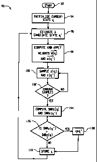
Fig. 7 is a flow diagram illustrating an exemplary method for calculating the
optimal
weight signal vector *opt. The method begins at step 92. In step 94, a current
state value q
is initialized. The initial value for q may, for example, be set zero, to some
pre-selected
estimate, or to any other value within the range of state values. Then, in
step 96, a candidate
state q' is estimated based on the current state q. The estimation for q' may,
for example, be
achieved by alternately selecting the state below and above the current state
q each time the
method 90 is repeated. For instance, in one pass through the method 90, the
candidate state q'
may be set to q+1, and then in the next pass the candidate state q' may be set
to q-1. In
another embodiment, the current state q could be initialized at either the
highest or lowest
state value, and then incremented or decremented each time each time the
method 90 is
repeated.
In step 98, two weight signal vectors *(q) and *(q') are calculated, as
described
above, with *(q) corresponding to the current state and *(q') corresponding to
the
candidate state. In an embodiment utilizing the Dual Decision Statistic Pilot
Rake Receiver
11
CA 02364986 2001-12-13
70 or a similar rake receiver, the two weight vectors *(q) and w(q' ) may be
calculated
simultaneously. In other embodiments, however, the weight vectors *(q) and
*(q') may
be calculated in succession using a rake receiver with a single output stage,
such as the rake
receiver described above with reference to Fig. 1.
Once the weight vectors *(q) and *(q') have been calculated and applied to a
rake
receiver, the current and candidate decision statistics z(q) and z(q') are
sampled from the
output of the rake receiver. Similar to the weight vector calculation
described in step 98, the
decision statistics z(q) and z(q') may be sampled simultaneously or
successively, depending
upon the type of rake receiver. Once a sufficient number of samples have been
calculated
such that the SNRz may be calculated with statistical significance (step 102),
the current and
candidate SNRz(q) and SNRz(q') are calculated in step 104.
If the current SNRz(q) is greater than the candidate SNRz(q') (step 106), then
the
current state q is set to the candidate state q' (step 108). Then, in step
110, the current state q
is stored, and the method repeats at step 96.
This written description uses examples to disclose the invention, including
the best
mode, and also to enable any person skilled in the art to make and use the
invention. The
patentable scope of the invention is defined by the claims, and may include
other examples
that occur to those skilled in the art.
12