Language selection

Search

Patent 2365005 Summary

Third-party information liability

Some of the information on this Web page has been provided by external sources. The Government of Canada is not responsible for the accuracy, reliability or currency of the information supplied by external sources. Users wishing to rely upon this information should consult directly with the source of the information. Content provided by external sources is not subject to official languages, privacy and accessibility requirements.

Claims and Abstract availability

Any discrepancies in the text and image of the Claims and Abstract are due to differing posting times. Text of the Claims and Abstract are posted:

  • At the time the application is open to public inspection;
  • At the time of issue of the patent (grant).
(12) Patent Application: (11) CA 2365005
(54) English Title: DRILL FOR MAKING WIDE DIAMETER AND HIGH DEPTH HOLES AND METHOD FOR CARRYING OUT SAID HOLES
(54) French Title: TREPAN PERMETTANT DE PRATIQUER DES TROUS PLUS LARGES ET PLUS PROFONDS ET PROCEDE AFFERENT
Status: Deemed Abandoned and Beyond the Period of Reinstatement - Pending Response to Notice of Disregarded Communication
Bibliographic Data
(51) International Patent Classification (IPC):
  • E21B 7/00 (2006.01)
  • E21B 27/00 (2006.01)
(72) Inventors :
  • ACCORRONI, GIULIO (Italy)
(73) Owners :
  • I.M.T. S.P.A.
(71) Applicants :
  • I.M.T. S.P.A. (Italy)
(74) Agent: BORDEN LADNER GERVAIS LLP
(74) Associate agent:
(45) Issued:
(86) PCT Filing Date: 2000-03-11
(87) Open to Public Inspection: 2000-09-14
Availability of licence: N/A
Dedicated to the Public: N/A
(25) Language of filing: English

Patent Cooperation Treaty (PCT): Yes
(86) PCT Filing Number: PCT/IB2000/000261
(87) International Publication Number: WO 2000053882
(85) National Entry: 2001-09-10

(30) Application Priority Data:
Application No. Country/Territory Date
PS99A000007 (Italy) 1999-03-11

Abstracts

English Abstract


A drill for drilling wide diameter and high depth holes in the soil including
a base machine (1) having a rotary (2) that is equipped with a clamp (9) and,
by means of translation cylinders (8), rotates and axially moves a series of
drill stem (7) having a tool (6) at the free end thereof, includes: a
hydraulic joint (3) linked to the rotary (2); at leat a winch (4) linked to
the hydraulic joint (3) and provided with at least a wire rope (18); a carrier
canister (5) slidely connected with the stem (7) between the rotary (2) and
the tool (6) by means of at least the wire rope (18); at least a winch (4), a
wire rope (18), a carrier canister (5) are rotated together with the stem (7)
of the rotary (2) in correspondence of an operating condition of the drill.


French Abstract

L'invention concerne un trépan permettant de pratiquer des trous plus larges et plus profonds dans le sol, le trépan comprenant une machine (1) de base dotée d'un élément rotatif (2) équipé d'une bride de serrage (9) et qui, grâce à des cylindres (8) de translation, effectue une rotation et déplace dans l'axe une série de trains de tiges (7) de forage comportant un outil (6) à leur extrémité libre, la machine de base comprenant : - un joint (3) hydraulique relié à l'élément rotatif (2) ; - au moins un treuil (4) relié au joint (3) hydraulique et comprenant au moins un câble métallique (18) ; - un contenant (5) de transport relié coulissant au train de tiges (7),entre l'élément rotatif (2) et l'outil (6), au moyen du câble métallique (18) ; le treuil (4), le câble métallique (18) et le contenant de transport (5) effectuant un mouvement de rotation en même temps que le train de tiges (7) de l'élément rotatif (2) pendant le fonctionnement du trépan.

Claims

Note: Claims are shown in the official language in which they were submitted.

7
CLAIMS
1) Drill for drilling wide diameter and high depth holes in the soil including
a base
machine (1) having a rotary (2) that is equipped with a clamp (9) and, by
means of
translation cylinders (8), rotates and axially moves a series of drill stem
(7) having a
tool (6) at the free end thereof, with said drill characterized in that
includes:
- an hydraulic joint (3) linked to the rotary (2);
- at least a winch (4) linked to the hydraulic joint (3) and provided with at
least a
wire rope (18);
- a carrier canister (5) slidely connected with the stem (7) between the
rotary (2)
and the tool (6) by means of at least the wire rope (18);
- at least a winch (4), a wire rope (18), a carrier canister (5) are rotated
together
with the stem (7) of the rotary (2) in correspondence of an operating
condition of
the drill.
2) Drill according to the claim 1 characterized in that the stems (7) have at
least a
longitudinally projecting guide (19) having the lower free end at a predefined
distance from the tool (6); the canister (5) has an axial inner sleeve (5')
having at
least an internal grove (21) into which the related guide (19) slides in
correspondence of the axial movement of the canister (5) along the stems (7),
each
of said grove (21) having a transversal shoulder (20) fit for stopping the
related free
end of the guide (19) in correspondence of a hooking condition (A)of the
canister
(5) to the series of stems (7).
3) Drill according to the claim 1 characterized in that the canister (5) is
provided of
drilling teeth (22) on the bottom.

8
4) Drill according to the claim 1 characterized in that the canister (5) is
provided with
opening lines (17) fit for carrying out the opening of the same canister (5).
5) Drill according to the claim 1 characterized in that it further includes a
conveyor
(13) placed near the base machine (1) for transporting the material carried
out by the
canister (5).
6) Drill according to the claim 1 characterized in that it further includes an
auxiliary
clamp (10) laying under the winch (4) fit for disassembling the stems (7).
7) Drill according to the claim 1 characterized in that it further includes a
loader (11)
of the stems (7) feeding these latter to a stem connection device (12).
8) Drill according to the claim 1 characterized in that the canister (5)
contains a inner
piston (14) linked to the wire ropes (18) fit for facilitating the loading of
material
into the same canister(5).
9) Drill according to the claim 1 characterized in that the tool (6) in
constituted by a
down hole-hammer trough which an air jet flows coming from a compressor (15)
trough a joint (16).
10) Method for drilling wide diameter and high depth holes in the soil
characterized in
that includes:
- the slidly descending along stems (7) a canister (5) till reaching the
drilled
material on the hole bottom;
- the rotation of the canister (5) pressing it on the hole bottom for
transferring the
material into the canister (5);

9
- the lifting of the canister (5) till the sole surface;
- the unloading of the canister (5).
11) Method according to the claim 10 characterized in that it further includes
the
activation of the tool (6) and stems (7) in correspondence of the desending,
loading
and unloading conditions.
12) Method according to the claim 11 characterized in that it further includes
the
activation of the tools (6) and stems (6) in correspondence of the lifting.
13) Method according to the claim 10 characterized in that in correspondence
of the
rotation of the canister (5), this latter drills.
14) Method according to the claim 10 characterized in that it includes, after
the
descending of the canister (5) onto the hole bottom, the rotation deactivation
of the
stems (7), the lifting of the stems (7) up to the contact of the tool (6) with
the
canister bottom, the reactivation of the stem rotation with the consequent
hooking of
these latter with the canister (5).
15) Method according to the claim 10 characterized in that it includes, before
the lifting,
the deactivation of the stem rotation, the counter-rotation of the stems (7)
causing
the axial release of the canister (5) from the stems (7).

Description

Note: Descriptions are shown in the official language in which they were submitted.


CA 02365005 2001-09-10
WO 00/53882 PCT/IB00/00261
DRILL FOR MAKING WIDE DIAMETER AND HIGH DEPTH HOLES AND
METHOD FOR CARRYING OUT SAID HOLES
TECHNICAL FIELD
The invention relates to a drill fit for carrying out wide diameter and high
depth holes,
especially for pilings and wells, and method for carrying out thereof.
BACKGROUND ART
to
The piles for the soil consolidation are commonly realized during the drilling
phase, the
reinforcement bar installation and concrete casting. The drillings are carried
out by
means of soil cutting or crumbling and carrying away the removed material.
Currently the material removing is done by means of either intermittent
transport, using
hammer grabs or a telescopic Kelly driven by a rotary, that must be lifted
each time, or
continuous transport by means of a cochlea or by fluid circulation.
The hammer grab utilization is limited to the scarce cohesion grounds,
particularly to
transport material trough the casing pipes.
Using the rotary with telescopic Kelly system is possible to make holes for
wide
diameter piles (up to 2-3 meters) but for limited depth, typically 50-60 m.
The depth
limit is due to the fact that the cutting and material transport tool is
linked to the inferior
end of series of telescopic stem fit to transmit the cutting torque. With the
hole depth
increasing, the stem IenUth or the number of the used elements must increase
with
difficulties imposing the cited limits.
CONF1RMATlON COPY

CA 02365005 2001-09-10
WO 00/53882 PCT/IB00/00261
Increasing the diameter, the resistance of said elements must be also
increased. So the
wide diameter and high depth holes can be obtained only with very high, heavy
and
expensive machines that sometimes don't have the required space to operate.
With the cochlea system, it is used an helix with the sharp tools in the
inferior part,
linked in the upper part to a rotary that drive the rotating movement and to
extraction
wire ropes. Said method requires high extraction forces and very high
machines, whose
height is comparable to the hole depth. Practically holes with 1,2-1,5 m as
maximum
diameter and 25-30 m as maximum depth are possible.
The circulating fluid systems require water pumps, or air compressors with
flows
growing with the diameter and depth increasing. Said systems allow to reach
very high
depth only if the working diameters are small (200-300 mm). Wider diameter
holes
(800-1400 mm) would be done using great flow rates required to the crumbled
material
lifting.
The reverse circulation system allows to drill deep and large diameter holes
lifting the
cut or crumbled material in a stream of water moved upward inside the stem by
compressed air. This system can be used only in waterproof soil or on the sea
or lakes
or making the hole waterproof thanks to expensive casings.
DISCLOSURE OF THE INVENTION
An object of the present invention is to allow the carrying out of great
diameter and
~5 high depth holes, for pilings or wells with an equipment limited in height,
weight and
cost, usable also under bridges, tunnels, buildings near electric cables, in
lakes and in
the sea.

CA 02365005 2001-09-10
WO 00/53882 PCT/IB00/00261
3
Another object is to hardly increase the hole execution speed.
According to the method and the machine of the present invention, the drilled
material
is carried to the surface by a carrier canister or similar that slides along
the drill stems
rotated by a rotary, being linked to ropes moved by winches rotating integral
with the
stems. So the material can be quickly and continuously removed, without
lifting and
moving the stems and without necessarily stopping the drilling operations.
The above described objects are obtained in accordance with the content of the
claims.
BRIEF DESCRIPTION OF THE DRAWINGS
The invention is now described, refernng to the enclosed drawings that show as
sample
some possible embodiments, in which:
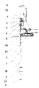
- figure 1 shows a schematic side view of the operating drill, with the
carrier canister
during the lifting phase;
- figures 2 and 3 show respectively a side and a cross sectional view of a
device for
hooking the Garner canister the stems, in the releasing condition, with the
free
sliding of the carrier canister;
- figure 4 and 5 show the same particulars of figures 2 and 3, in the hooking
condition;
- figure 6 and 7 show two schematic side views of the drill equipped with a
piston
carrier canister, during two different working phases;
- figure 8 shows a schematic side view of the working drill, equipped with a
down
hole-hammer and linked to a compressor;
- figure 9 shows a variant of the drill of figure 1 used for making high depth
and wide
diameter holes.

CA 02365005 2001-09-10
WO 00/53882 PCT/IB00/00261
4
BEST MODE OF CARRYING OUT THE INVENTION
In figure l, numeral 1 shows a basic machine that supplies hydraulic power to
the rotary
2, and, by means of an hydraulic joint 3, to the winches 4, that rotate
integral with the
drill stems 7 having a plurality of longitudinal projecting guides 19. The
numeral 5
show the carrier canister that is driven in the vertical movements by wire
ropes 18 of the
winches 4.
The numeral 6 indicates the drill tool, linked to the stem 7 inferior end. The
penetration
to and extraction force is driven from the translation cylinders 8 of the
rotary to the drill
tool 6 by means of the stems 7 with a stem clamp 9.
The numeral 10 shows an auxiliary clamp that allows the stem holding during
the
extraction phase to facilitate the disassembling of this latter. The drill
stems 7 are loaded
by a loader 11 and connected by a device 12. The numeral 13 shows a conveyor
for
moving the removed material.
In figures 2, 3, 4 and 5, the numeral 5' refers to an inner sleeve of the
canister 5,
provided with longitudinal grooves 21 of different width forming a shoulder
20.
The drilling material can be continuously carned to the surface, without
stopping the
drill and without lifting the stems, by means of the Garner canister 5 sliding
on the drill
stem 7, pulled by the wire ropes 18 linked to the winches 4 rotating integral
with the
stems.
To keep the carrier canister 5 down during the loading phase and to release it
during the
unloading phase, the automatic hooking device comprises the inner sleeve 5'.
The

CA 02365005 2001-09-10
WO 00/53882 PCT/IB00/00261
inferior ends of the longitudinal projecting guides 19 can engage the shoulder
20
obtained by the longitudinal grooves 21.
At the end of the descendant run, the Garner canister 5 reaches the soil
removed by the
5 drill tool 6 during the ascendant, unload and descendant phases of the
canister 5. To
carry out the connection between the canister 5 and the stem inferior end, the
stem
clamp 9 clamps the stems 7 to the rotary 2 that is lifted by means of the
translation
cylinder 8, until the wire ropes 18 are loosed showing that the canister 5 is
properly
lifted by the drill tool 6. The rotary 2 rotates the drill stem 7 in the
drilling rotation sense
causing the overlay of the lower end of the longitudinal guides 19 on the
shoulder 20
causing the automatic linkage between the stem 7 and the inner sleeve 5' of
the canister
5. The above mentioned rotation in combination with a downward translation
causes the
opening of axial or radial valves, known and not illustrated, of the canister
bottom that,
consequently, can collect the removed soil.
In the hooking condition A of the canister 5 to the stem 7 by means of the
inner sleeve
5', the canister 5 rotates integral with the steams 7. The canister 5 can be
equipped with
bottom drill tools that, because of rotation, digs the soil together with the
drill toll 6,
consequently the diameter of the hole can be wider than the diameter of the
drill toll 6
and equal to the diameter of the canister 5.
In the variant according to figures 6 and 7, the Garner canister 5 has an
inner piston 14
sliding inside the canister 5 and connected to the wire ropes 18 that
facilitates the
loading.
The piston 14, when is pulled by the wire ropes 18, intakes the removed soil
inside the
canister 5.

CA 02365005 2001-09-10
WO 00/53882 PCT/IB00/00261
6
In this variant the drill tool 6 has the same diameter of the canister 5 that,
consequently,
is not equipped with bottom drill tools.
In the variant of the drill according to figure 8 the numeral 16 indicates a
joint
connecting the stem bore to the outlet pipeline of an air compressor 15 and
the drill tool
6 consists of a down hole-hammer or similar destruction tool.
In such case the compressed air coming from the compressor removes the
material from
the tool teeth or roller bit avoiding the obstruction of the drill tool 6. The
flow supplied
l0 by the compressor is low because the material must be moved and not lifted
to the
surface.
Whatever variant used, the method and the drill of the present invention can
quickly
drill wide diameter and high depth holes and can also working near bridges,
buildings,
electric power line or other obstacles, in lakes and sea.
A variant of the Garner canister of the drill has a structure that can be
opened, for
example, along the opening line 17 of figure 9 so allowing the easy
discharging of the
carned material into the surface.

Representative Drawing
A single figure which represents the drawing illustrating the invention.
Administrative Status

2024-08-01:As part of the Next Generation Patents (NGP) transition, the Canadian Patents Database (CPD) now contains a more detailed Event History, which replicates the Event Log of our new back-office solution.

Please note that "Inactive:" events refers to events no longer in use in our new back-office solution.

For a clearer understanding of the status of the application/patent presented on this page, the site Disclaimer , as well as the definitions for Patent , Event History , Maintenance Fee  and Payment History  should be consulted.

Event History

Description Date
Time Limit for Reversal Expired 2005-03-11
Application Not Reinstated by Deadline 2005-03-11
Deemed Abandoned - Failure to Respond to Maintenance Fee Notice 2004-03-11
Letter Sent 2002-11-04
Inactive: Single transfer 2002-09-05
Inactive: Entity size changed 2002-03-20
Inactive: Cover page published 2002-02-05
Inactive: Courtesy letter - Evidence 2002-02-05
Inactive: Notice - National entry - No RFE 2002-01-31
Inactive: First IPC assigned 2002-01-31
Application Received - PCT 2002-01-16
Amendment Received - Voluntary Amendment 2001-09-11
Application Published (Open to Public Inspection) 2000-09-14

Abandonment History

Abandonment Date Reason Reinstatement Date
2004-03-11

Maintenance Fee

The last payment was received on 2003-03-11

Note : If the full payment has not been received on or before the date indicated, a further fee may be required which may be one of the following

  • the reinstatement fee;
  • the late payment fee; or
  • additional fee to reverse deemed expiry.

Please refer to the CIPO Patent Fees web page to see all current fee amounts.

Fee History

Fee Type Anniversary Year Due Date Paid Date
Basic national fee - small 2001-09-10
MF (application, 2nd anniv.) - standard 02 2002-03-11 2002-03-11
Registration of a document 2002-09-05
MF (application, 3rd anniv.) - standard 03 2003-03-11 2003-03-11
Owners on Record

Note: Records showing the ownership history in alphabetical order.

Current Owners on Record
I.M.T. S.P.A.
Past Owners on Record
GIULIO ACCORRONI
Past Owners that do not appear in the "Owners on Record" listing will appear in other documentation within the application.
Documents

To view selected files, please enter reCAPTCHA code :


To view images, click a link in the Document Description column. To download the documents, select one or more checkboxes in the first column and then click the "Download Selected in PDF format (Zip Archive)" or the "Download Selected as Single PDF" button.

List of published and non-published patent-specific documents on the CPD .

If you have any difficulty accessing content, you can call the Client Service Centre at 1-866-997-1936 or send them an e-mail at CIPO Client Service Centre.


Document
Description 
Date
(yyyy-mm-dd) 
Number of pages   Size of Image (KB) 
Representative drawing 2002-02-04 1 7
Cover Page 2002-02-05 2 43
Abstract 2001-09-10 1 56
Drawings 2001-09-10 5 94
Claims 2001-09-10 3 91
Description 2001-09-10 6 197
Reminder of maintenance fee due 2002-01-31 1 111
Notice of National Entry 2002-01-31 1 193
Request for evidence or missing transfer 2002-09-11 1 108
Courtesy - Certificate of registration (related document(s)) 2002-11-04 1 109
Courtesy - Abandonment Letter (Maintenance Fee) 2004-05-06 1 175
Reminder - Request for Examination 2004-11-15 1 116
PCT 2001-09-10 3 94
Correspondence 2002-01-31 1 25
PCT 2001-09-11 5 188