Note: Descriptions are shown in the official language in which they were submitted.
CA 02365044 2006-04-28
1 BACKGROUND OF THE INVENTION
2
3
4
6 This invention relates generally to
7 electrical logging of formations surrounding a
8 borehole; more particularly, it relates to measuring
9 formation resistivity by processing signals induced in
receiving antennae by electromagnetic waves that are
11 caused to propagate through the formation by
12 transmitting antennae.
13 The prior art shows certain methods and
14 apparatus for such logging of formation resistivity.
Examples are known both for independent logging
16 operations and for logging during measure while
17 drilling (MWD) operations. Typical examples are shown
18 by U.S. Patents 3,891,916, 4,107,598 and 4,513,693. In
19 these examples a number of antennae, some transmitting
and some receiving, are disposed on the outside of, or
21 embedded in the outer surfaces of, a drill collar or
22 other elongated tubular member. Electronic equipment
23 located interior to the drill collar or elongated
24 tubular member provides power excitation to
transmitting antennae, typically in the frequency range
1
CA 02365044 2006-04-28
1 of a few hundred kilohertz to a few megahertz.
2 Electromagnetic energy transmitted through the borehole
3 formation--exterior to the collar or tubular-membe-r is
4 sensed by receiving antennae. Signals from such
receiving antennae are processed by electronic
6 equipment interior to the collar or tubular member to
7 provide data that is indicative of the formation
8 resistivity of the material surrounding the borehole.
9 Generally, such signal processing measures the phase
velocity (phase difference) and the attenuation
11 (amplitude ratio) of the electromagnetic wave energy as
12 it propagates past the receiving antennae.
13 The external placement of the antennae leads
14 to various problems with mechanical damage to such
antennae in use. Several outer shielding or covering
16 approaches are known to provide some protection to the
17 antenna structures. Recently, U.S. Patent 5,530,358
18 describes and claims an improved antenna system for
19 resistivity tools, in which antenna elements are
embedded within the drill collar or elongated tubular
21 member. The antenna elements are exposed to the
22 exterior region by a plurality of discrete
23 communication regions. These discrete communication
24 regions are elements of a contoured portion of the
outer peripheral surface of the collar or tubular
26 member, and that have a reduced radial dimension. The
2
CA 02365044 2006-04-28
1 antenna coils are disposed circularly around the
2 elongated tubular member at a radius between that of
3 the outer- surface and the----inside radius--of the siot-s.
4 The objective of this configuration is to provide
protection to the antenna elements. Further, means are
6 known to provide for directional variation of the
7 antenna pattern.
8 U.S. patent 5,682,099 describes, but does not
9 claim, a drill collar or measurement tubular for a
resistivity tool having slots completely through the
11 collar from the exterior to the interior in the region
12 of the antennae but does not show or suggest that such
13 a configuration permits a retrievable sonde or tool.
14 U.S. patent 5,939,885 describes and claims a tubular
body member having apertures therein and a mounting
16 member comprising two portions to permit the antenna to
17 be mounted or removed from the mounting member. Again,
18 there is no indication that such a configuration can be
19 used to provide a retrievable resistivity sonde or
tool.
21 One significant problem all such prior art
22 approaches is that the antenna elements are fixed, in
23 one way or another, within or exterior to the collar or
24 tubular element. Thus, they can only be removed from
the borehole by completely withdrawing the entire drill
26 string from the borehole. With this approach, it is
3
CA 02365044 2006-04-28
1 impossible to withdraw an antenna structure to correct
2 a failure or to remove the complete logging apparatus
3 or to change the antenna structure to a-different
4 configuration without the added cost and time required
for pulling the entire drill string from the borehole.
6 The shortcomings of existing technologies are
7 well known and there is a need for improvements to such
8 resistivity tools to overcome them. It is the
9 objective of this invention to provide an improved
resistivity tool that overcomes some of the
11 difficulties and expense associated with the prior art
12 tools.
13
14 SUMMARY OF THE INVENTION
16 This invention provides a resistivity
17 measurement tool that is entirely contained within the
18 interior of the drill collar or elongated tubular
19 member. As such, the complete resistivity tool can be
retrieved as a unit, antennae as well as electronic
21 elements.
22 Careful electromagnetic and structural
23 analyses have shown that suitable resistivity logging
24 and suitable mechanical strength can be obtained in a
structure similar to that shown at Fig. 3AA in U.S.
4
CA 02365044 2006-04-28
1 patent 5,682,099 that has slots, of several possible
2 configurations, extending completely through the collar
3 or elongated tubular member from the exterior surface.
4 Antenna elements located completely internal to the
collar and in the region of the slots provide suitable
6 coupling of energy into the formation, and detection of
7 such signals resulting from such transmission through
8 the formation, to obtain the desired measurement of
9 formation resistivity.
In one embodiment, a number of slots are cut
11 through the entire thickness of the collar or elongated
12 tubular member symmetrically over each of the antenna
13 elements. Such slots may, for example, be axial in
14 direction and generally of much greater length along
the borehole axis than the width of such slots. The
16 effectiveness of the antenna elements interior to the
17 collar depends on the number of slots, the length of
18 the slots, the width of the slots and the axial
19 location of the antenna elements with respect to the
slotted region. The mechanical strength of the collar
21 or elongated tubular member depends on the number of
22 slots, the length of the slots and the width of the
23 slots. Detailed finite element analysis of both the
24 electromagnetic effectiveness and the mechanical
strength for various combinations enables selection of
26 those combinations that are suitable for the intended
5
CA 02365044 2006-04-28
1 purpose of formation resistivity measurement wile
2 maintaining adequate mechanical strength of the string.
3 The slots may be filled with epoxy, ceramic
4 or other insulating material to provide a seal to
prevent formation fluids from flowing into the internal
6 apparatus. Slots may be tapered so as to be wider on
7 the interior side than on the exterior side so that the
8 normally higher internal pressure will force the slot
9 filler into the slot. Although axial slots represent
the preferred embodiment, other configurations are
11 possible. Slots may be diagonal, crosswise or zigzag
12 with respect to the borehole axis. Slots may generally
13 be in the range of .05 to .5 inches in width and on the
14 order of 4 inches long. The number of slots may range
from a low of one to as many as twenty to thirty or
16 more for each antenna region location.
17 The general electronic structure for this
18 invention is known. Electronic components and
19 functions include circuits for power conditioning, for
generation of the desired high frequency power to be
21 applied to the transmitting antennae, for the detection
22 of the desired signals from the receiving antennae, for
23 processing such received signals to determine measures
24 of formation resistivity and for conditioning such
formation resistivity data to a form suitable for
26 transmission to the surface or for storing in other
6
, CA 02365044 2006-04-28
1 downhole apparatus. One or more frequencies in the
2 range from about 100 KHZ to about 4 MHZ may be
3 generated and transmitted into the-formation. Data
4 output from the formation resistivity tool may be
transmitted to the surface by well known means such as
6 mud pulse telemetry, electromagnetic telemetry or
7 conventional wireline.
8 The use of a slotted collar or elongated
9 tubular member permits provision of an integrated and
separate antenna tool or sonde having all of the
11 elements in a single unit which is one important
12 objective of the invention. Such an integrated tool
13 reduces cost of manufacture, while maintaining
14 retrievability from the interior of the drill string,
without pulling the entire drill string resulting in
16 substantial cost savings in use. The integrated tool
17 can be used inside different other structures, and
18 since it is complete including its antennae, it can be
19 used for formation resistivity logging in an open hole.
Accordingly, a major object is to provide
21 apparatus for the measurement in a borehole of
22 resistivity of the formation external to the borehole,
23 comprising:
24 a) longitudinally elongated tubular
structure adapted to be located in the borehole, and
26 having exterior and interior surfaces and a selected
7
- CA 02365044 2006-04-28
1 configuration of a slot or slots extending completely
2 through the structure between its exterior surface and
~3 its interior surface,
4 b) a sonde or tool completely contained
within the interior of the tubular structure to be
6 relatively movable lengthwise therein, and having:
7 1. one or more electromagnetic energy
8 transmitting antennae positioned
9 proximate a certain slot or certain
of said slots,
11 2. one or more electromagnetic energy
12 receiving antennae positioned
13 proximate another slot or other
14 selected slots,
3. and electronic elements to provide
16 radio frequency power to the
17 transmitting antennae to cause
18 transmission of electromagnetic
19 energy into the sub-surface
formation via said certain slot or
21 certain of the slots, receiving
22 means to receive radio frequency
23 signals arriving at the receiving
24 antennae from the sub-surface
formation via said other slot or
26 other selected slots.
8
CA 02365044 2006-04-28
1 In addition, processing means are typically
2 operatively connected to output from the receiving
3 means to provide data indicative of formation
4 resistivity at the exterior of the collar or tubular
structure, and means is provided to communicate such
6 data to other equipment, or to store the data.
7 Also provided is structure to support
8 elements of the sonde or tool, and attachment means for
9 moving the sonde with respect to the collar.
These and other objects and advantages of the
11 invention, as well as the details of an illustrative
12 embodiment, will be more fully understood from the
13 following specification and drawings, in which:
14
DRAWING DESCRIPTION
16
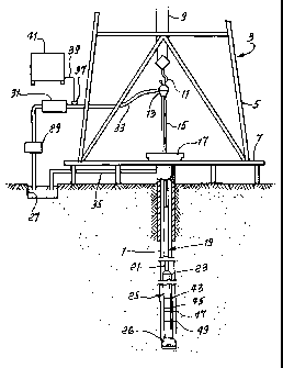
17 Fig. 1 is a schematic view of a drill string
18 in a borehole for simultaneously drilling and logging a
19 well, in which a logging collar includes a formation-
resistivity measurement system;
21 Fig. 2 is a schematic view of a formation-
22 resistivity measurement system of the prior art showing
23 transmitting and receiving antennae on the exterior of
24 the logging collar carried by a drill string;
9
CA 02365044 2006-04-28
1 Fig. 3 is a view of another example of the
2 prior art having an antenna embedded within the drill
3 collar, with the antenna elements exposed-to the
4 exterior region of the collar through a plurality of
recesses sunk in the exterior surface of the collar,
6 such recesses not extending to the interior of the
7 collar;
8 Fig. 4 is a cross section through a region of
9 Fig. 3 showing the radial extent of the recesses in the
collar;
11 Fig. 4a is an elevation showing another
12 example of prior tubular apparatus;
13 Figs. 5a, 5b, 5c, and 5d are cross sections
14 of one preferred collar or collars of the present
invention, taken perpendicular to the borehole axis and
16 showing slots extending completely through the collar,
17 to be aligned with transmitting and receiving antennae.
18 Four different configurations of slots are shown in the
19 four figures;
Fig. 6 is a cross section of a collar
21 according to the present invention, taken along the
22 borehole axis and showing typical widths and lengths of
23 the slots;
24 Fig. 7a shows a view of a collar of the
present invention having slots for one transmitting
26 antenna and three receiving antennae;
CA 02365044 2006-04-28
1 Fig. 7b shows a view of a collar of the
2 present invention having slots for two transmitting
3 antennae and three receivi-ng antennae;
4 Fig. 8a is an enlarged cross section from
Fig. 7a taken along the borehole axis to intersect the
6 slots, and showing the collar and the transmitting and
7 receiving antennae on a carrier movable within the pipe
8 string;
9 Fig. 8b is a cross section from Fig. 7b taken
along the borehole axis to intersect the slots, and
11 showing the collar and the transmitting and receiving
12 antennae on an axially removable carrier;
13 Fig. 9 shows a view of an alternative
14 configuration for slots in the collar that provides the
electromagnetic energy passing equivalent of long slots
16 through provision of a plurality of shorter slots;
17 Fig. 10 presents results of mechanical stress
18 computation, showing the torsional stress on the
19 slotted collar, as a function of the number of slots
for a given set of material and slot dimensions;
21 Fig. 11 is a schematic drawing showing
22 antennae on a carrier in a pipe string, with associated
23 circuitry;
24 Fig. 12 shows a fishing neck on the upper end
of the sonde for retrieval from the borehole;
11
CA 02365044 2006-04-28
1 Fig. 13 is an elevation taken in section,
2 showing elements of a transmitter assembly on a sonde;
3 Fig.-14 -i-s an exploded view-- of -the- Fig. 13
4 elements;
Fig. 15 is an elevation taken in section,
6 showing elements of a receiver assembly, on a sonde;
7 Fig. 16 is an exploded view of the Fig. 15
8 elements;
9 Fig. 17 is an elevation, in section, showing
a field joint connector;
11 Fig. 18 is an exploded view of the Fig. 17
12 connector;
13 Fig. 19 is a fragmentary section taken at a
14 coil location; and
Figs. 20 and 21 are circuit diagrams.
16
17 DETAILED DESCRIPTION
18
19 With reference to Fig. 1 and to the
disclosure in U.S. Patent 5,081,419, to Meador, there
21 will now be described an overall simultaneous drilling
22 and logging system that incorporates an electromagnetic
23 wave propagation (EWP) resistivity measurement system.
24 A well 1 is being drilled into the earth
under control of surface equipment including a rotary
12
CA 02365044 2006-04-28
1 drilling rig 3. In accord with a conventional
2 arrangement, rig 3 includes a derrick 5, derrick floor
3 7, draw wor-ks 9, hook 11, swivel 13, kelly joint 15,
4 rotary table 17, and drill string 19 that includes
drill pipe 21 secured to the lower end of kelly joint
6 15, and to the upper end of a section of drill.collars
7 including an upper drill collar 23, and intermediate
8 drill collar or sub (not separately shown), and a lower
9 drill collar or sub 25 immediately below the
intermediate sub. A drill bit 26 is carried at the
11 lower end of sub 25.
12 Drilling fluid (or mud, as it is commonly
13 called) is circulated from a mud pit 27 through a mud
14 pump 29, past a desurger 31, through a mud supply line
33, and into swivel 13. The drilling mud flows down
16 through the kelly joint and an axial tubular conduit in
17 the drill string, and down through jets (not shown) in
18 the lower face of the drill bit. The drilling mud
19 flows back up through the annular space between the
outer surface of the drill string and the inner surface
21 of the borehole to be circulated to the surface, where
22 it is returned to the mud pit through a mud return line
23 35. A shaker screen (not shown) separates formation
24 cuttings from the drilling mud before it returns to the
mud pit.
13
CA 02365044 2006-04-28
1 The overall system of Fig. 1 uses mud pulse
2 telemetry techniques to communicate data from downhole
3 to the surface while the drilling operation takes
4 place. To receive data at the surface, there is a
transducer 37 in mud supply line 33. This transducer
6 generates electrical signals in response to drilling
7 mud pressure variations, and these electrical signals
8 are transmitted by a surface conductor 39 to a surface
9 electronic processing system 41.
As explained in U.S. Patent 4,216,536 to
11 More, mud pulse telemetry techniques provide for
12 communicating data to the surface indicative of
13 numerous downhole conditions sensed by well logging
14 transducers or measurement systems that ordinarily are
located on and within the drill collar nearest the
16 drill bit, as shown in Fig. 1. The mud pulses that
17 define the data propagated to the surface are produced
18 by equipment within the intermediate sub. Such
19 equipment suitably comprises a pressure puls.e generator
operating under control of electronics contained within
21 an instrument housing to allow drilling mud to vent
22 through an orifice extending through the logging collar
23 wall. Each time the pressure pulse generator causes
24 such venting, a negative pressure pulse is transmitted
to be received by surface transducer 37. An
14
CA 02365044 2006-04-28
1 alternative conventional arrangement generates and
2 transmits positive pressure pulses.
3 The circulating drilling mud typically
4 provides a source of energy for a turbine-driven
generator sub-assembly located in the intermediate sub,
6 and the turbine-driven generator sub-assembly generates
7 electrical power for the pressure pulse generator and
8 for various circuits including circuits forming part of
9 the preferred embodiment of this invention.
A measurement system includes electronics
11 contained in electronics housings contained within the
12 axial tubular conduit of sub 25, and contains elements
13 arranged in recesses or necked-down portions of the
14 tubular steel housing of sub 25. Some of these
elements on sub 25 are indicated in Fig. 1, and include
16 four antenna-insulating sleeves 43, 45, 47, and 49,
17 each of which surrounds a longitudinally-extending,
18 necked-down portion of sub 25.
19 The prior art (U.S. Patent 4,785,247) system
of Fig. 2 schematically shows drill string 111
21 positioned in borehole 112 traversing earth formations
22 113. The drill string includes sections of drill pipe
23 and, at the lower end of the string, drill collars to
24 provide weight to the system. A MWD logging apparatus
is housed in drill collar or logging sub 114 or the
26 like which is illustrated positioned in the drill
CA 02365044 2006-04-28
1 string above drill bit 116. The logging sub 114 is
2 illustrated having longitudinal passage 117 for
3 providing drilling fluid or mud flow through -t-he system
4 and access to the bottom of the drill string. Such
access is desirable for a number of reasons which are
6 known to those skilled in the art and, therefore, will
7 not be discussed here. Power supply and electronic
8 circuit components for operating the system are housed
9 in circumferential compartments 118 in the wall of sub
114 arranged about the passage 117. Transmitter
11 antenna 119 and receiver antennae 121 and 122 having an
12 annular configuration are illustrated, arranged about
13 collar 114 and spaced apart to provide the comparison
14 of travel time and attenuation as described above.
An electromagnetic wave from the transmitter
16 antenna 119, corresponding to transmitter antenna T,
17 penetrates surrounding formations 113. The wave
18 propagated within the formation in the vicinity of sub
19 114 is first received at receiver antenna 122 spaced
relatively closer along the sub to transmitter antenna
21 119 than receiver antenna 121. The propagated wave
22 indicated at 108 is received later by a delay time
23 " D" at receiver antenna 121, spaced relatively
24 farther along the sub from transmitter antenna 119.
Reference is now made to prior art apparatus
26 (U.S. Patent 5,530,358) shown in Figs. 3 and 4. Fig. 3
16
CA 02365044 2006-04-28
1 is a perspective and fragmentary view of modified
2 tubular collar or pipe element 139 which accommodates
3 one or more antenna windings. Tubular element 139
4 includes outer peripheral surface 143 which includes
contoured portion 145 having a plurality of discrete
6 communication regions 147 of reduced radial dimension,
7 i.e. recesses in surface 143. Preferably, as is shown,
8 discrete communication regions 147 comprise a plurality
9 of axial recesses formed within tubular element 139,
and which are spaced at or about outer peripheral
11 surface 143, in a predetermined manner. As is shown,
12 axial recesses 151, 153, 157, 159, 161, 163, 165, 167,
13 169 and 171 define regions of reduced radial dimension,
14 which fare separated by land members 173, 175, 177,
179, 181, 183, 185, 187 and 189 of a radial dimension
16 equal to the wall thickness of tubular element 139.
17 Two antenna pathways are defined in the body
18 of the material which comprises modified tubular
19 element 139. Antenna pathways 191 and 193 communicate
with the discrete communication regions 147 defined by
21 the axially extending recesses. Both antenna pathway
22 191 and antenna pathway 193 are generally circular in
23 shape, and transverse in orientation to both the
24 longitudinal axis 188 of tubular element 139 and
discrete communication regions 147 defined by the axial
26 recesses. As is shown, antenna pathways 191, 193,
17
CA 02365044 2006-04-28
1 extend through each of the land portions which are
2 disposed between the axial recesses, but not through
3 the wall of tubular el-ement 149. Typically, element
4 139 is formed of steel, so the antenna windings
disposed in the antenna pathways 191 and 193 will
6 communicate electromagnetic energy (either transmitting
7 or receiving) through the portions of the antenna
8 windings disposed within discrete communication regions
9 147, but will not perform any substantial communication
with the wellbore and surrounding formation with
11 antenna portions which are disposed in segments of
12 antenna pathways 191 and 193 which are enclosed by the
13 material which forms modified tubular element 139. In
14 other words, the discrete communication regions 147
define portions of an antenna which are capable of
16 communication of electromagnetic energy, while those
17 portions of the antenna not located within discrete
18 communication regions 147 are not very effective at
19 communicating electromagnetic energy. The axial
grooves or recesses which define the discrete
21 communication regions 147 each comprise a groove or
22 recess which is three inches long, one-half inch deep,
23 and one-eighth of an inch wide. Tubular element 139
24 further includes a junction box which is machined into
element 139, and which allows for the threading of the
26 antennae through the antenna pathways 191, 193, and
18
CA 02365044 2006-04-28
1 which also houses electronics associated with the
2 antenna. In particular, a junction box 149 houses one
3 pick-up coil, preferably a toroid, which is utilized to
4 detect current in a receiving antenna, and one or more
capacitors or other electrical components which are
6 utilized to tune the antenna windings to be responsive
7 to particular frequencies or frequency ranges; although
8 voltage across the coil could be monitored instead of
9 current. A drilled or milled wireway is provided (but
not depicted) to allow electrical signals to be passed
11 via a wire to signal conditioning and signal processing
12 equipment.
13 As shown in Fig. 4, discrete communication
14 regions 147 are disposed in three groupings, including
recess group 131, group 133, and group 135. Groups
16 131, 133 are disposed adjacent junction box 149. This
17 particular geometric configuration is for the purpose
18 of obtaining a particular antenna gain response, and is
19 used because the portion of the tubular element 149
which includes the junction box 149 provides a region
21 which is less able to accommodate magnetic flux.
22 Note that the antennae are carried by 149,
23 and cannot be removed from the well bore, without
24 retrieving the drill string.
Fig. 4a shows another example from prior art,
26 as seen in Fig. 3AA of U.S patent 5,682,099.
19
CA 02365044 2006-04-28
1 Measurement tubular 2401 is composed substantially of
2 steel as are the other prior drill collars; however,
3 measurement tubular 2401 includes four regions which
4 include a plurality of axial slots which are disposed
circumferentially about measurement tubular 2401 and
6 which extend through the wall of measurement 2401, but
7 which are filled with a poorly-conducting material.
8 Upper transmitter region 2402 includes the axial slots
9 which allow for the inward and outward passage of
electric and/or magnetic oscillating fields. Likewise,
11 lower transmitter region 2407 includes the axial slots
12 which allow for the inward or outward passage of
13 electric and/or magnetic fields. Receiver regions
14 2403, 2405 are provided in a position intermediate the
transmitter regions 2402, 2407. Receiver regions 2403.
16 2405 also include axial slots filled with a poorly-
17 conducting or non-conducting material, which allow for
18 the inward or outward passage of electric and/or
19 magnetic fields. Nothing is disclosed with respect to
a retrievable sonde or tool.
21
22 PRESENT INVENTION
23
24 In all of the described prior art, except for
U.S. patents 5,682,099 and 5,939,885, the various
CA 02365044 2006-04-28
1 transmitting and receiving antennae are either exterior
2 to or integrated into the drill collar. This
3 configuration makes it impossible to withdraw the
4 antennae structure from the borehole without
withdrawing the complete drill string from the
6 borehole. Those two patents disclose a sonde or tool
7 within the interior of the drill collar, but the
8 electronics and/or antennae are not disclosed as
9 retrievable in a sonde.
Fig. 5a shows one such configuration of slots
11 in a cross section of the collar 200. The collar 200
12 has an exterior surface 201 and an internal surface
13 202. Extending completely through the collar from the
14 external to internal surface are slots 203a. Although
four slots are shown in the figure, the number used may
16 usefully lie in the range of 1 to about 30. The widths
17 of the slots, crosswise to the borehole axis may
18 typically be in the range of 0.05 inches to 0.5 inches.
19 The lengths of the slots along the borehole axis
direction may typically be in the range of about 4
21 inches in length. However, shorter or longer slots may
22 be used. The number of slots and their dimensions are
23 only restricted by the strength of the collar. For
24 given slot dimensions, generally the strength of the
collar decreases as the number of slots increases. The
26 number of slots and their dimensions are only
21
CA 02365044 2006-04-28
1 restricted by the strength of the collar. The number
2 and width of the slots must be balanced with the
3 strength and durability of the collar.
4 The slots of Fig. 5a are shown as being of
constant width from the exterior of the collar 201 to
6 the interior of the collar 202. Also shown is an
7 antenna 400 carried by and extending about a carrier or
8 sonde 401, movable axially within the collar, so as to
9 be retrievable. Figs. 5b, 5c and 5d show alternative
variations of the slot width from the exterior surface
11 to the interior surface. In Fig. 5b the slots 203b are
12 wider at the interior surface 202 than at the exterior
13 surface 201. Such a configuration is of value if the
14 slots are to be filled with some sort of insulating
material such as epoxy, or ceramic, that transmits
16 radio frequency energy. One slot is shown containing
17 such material, at 198. (The steel wall of the collar
18 does not transmit such energy. The collar may consist
19 of non-magnetic material, such as Inconel.) In the
drilling process, material is pumped down the interior
21 of the drill pipe to provide cooling for the drill bit
22 and to flush cuttings from the drill area toward the
23 surface of the earth. This pumping leads to a higher
24 internal pressure in a drill collar than the external
pressure. Thus in a configuration like Fig. 5b the
26 internal pressure would force the insulating material
22
=, CA 02365044 2006-04-28
1 into the narrowing slot which would help to keep the
2 insulating material in the desired location. In Fig.
3 5c the slots 203c are wider at the exterior surface 201
4 than at the interior surface 202. Such a configuration
would keep the insulation 198a in the slot should the
6 external pressure be higher than the internal pressure.
7 The insulating material, such as synthetic resin, also
8 prevents fluid leakage.
9 In Fig. 5d a configuration that combines
elements of Fig. 5b and 5c is shown. Slots 203d
11 decrease in width from the exterior surface 201 toward
12 the interior surface 202 until a point having an
13 intermediate radius 204 is reached. Beyond this point
14 the width of the slots 203d increases again toward the
inner surface 201. This configuration provides
16 benefits that combine those of the configurations shown
17 in Figs. Sb and 5c. See filler 198b, bridging locus
18 204.
19 Fig. 6 shows a cross section through an axis
along the borehole direction for a collar with slots as
21 in Fig. 5a.
22 Fig. 7a shows an external view of a collar of
23 the subject invention showing four sets of slots 203a
24 spaced apart along the borehole axis. One set, to the
left, is for a transmitter antenna, to be shown later.
26 Three sets, to the right, are provided for receiving
23
CA 02365044 2006-04-28
1 antenna, also to be shown later. The spacings shown in
2 the figure are selected to provide the desired degree
3 of penetration of the transmitted energy into the
4 surrounding formation. Methods for selection of such
spacings are well known to those skilled in the arts of
6 formation resistivity measurement. Fig. 7b shows an
7 alternative external view having two sets of slots for
8 transmitting antennae. In each view, slots are
9 typically spaced about the axis of the collar.
Fig. 8a shows a section equivalent to Fig.
11 7a. Internal to the collar 200 with its slots 203a is
12 a sonde 210 that contains the receiving antennae 215,
13 the transmitting antenna 220 and all of the electronics
14 needed to provide radio frequency power to the
transmitting antenna, receiving means to detect signals
16 arriving at the receiving antennae, processing means to
17 provide data indicative of formation resistivity on the
18 exterior of the collar and means to communicate such
19 data to other equipment or to store such data. The
sonde 210 may also include any required energy storage
21 means, energy generation means or power conversion
22 means required to operate the other electronics of the
23 sonde. Details of such electronics elements needed for
24 formation resistivity evaluation are well known to
those skilled in the formation resistivity evaluation
26 arts. The frequency of the radio frequency power
24
CA 02365044 2006-04-28
1 provided to the transmitting antenna is typically in
2 the range of 100KHz to 4MHz. The transmitting and
3 receiving antennae are typically solenoidal coils
4 having the axis of the solenoid along the borehole
axis. One or more turns of wire may be used in such
6 coils, the number determined by the desired impedence,
7 frequency and sensitivity of the apparatus. Fig. 8b
8 shows an alternative cross section view having two sets
9 of slots 203a for transmitting antennae and two
corresponding transmitting antennae 220.
11 As shown in Figs. 8a and Sb, there is no
12 required connection between the sonde 210 and the
13 collar 200. Thus the sonde can be completely withdrawn
14 from the interior of the collar and drill string
without withdrawal of the collar and drill string from
16 the borehole.
17 In the preceeding discussions, each slot
18 associated with a single antenna has been shown as a
19 complete slot extending in length along the borehole a
substantial distance that is significantly greater than
21 the length of the related antenna element along the
22 borehole. Fig. 9 shows an alternative to this in which
23 each desired through slot is broken into a number of
24 individual slot segments, each of shorter dimension
than the desired equivalent slot length. For example
26 short slot segments 205-1, 205-2 and 205-3 combine to
CA 02365044 2006-04-28
1 provide a communication path from the interior of the
2 collar to the exterior of the collar that is nearly as
3 effective as a single longer slot. Such a
4 configuration of shorter slots or segments to make up
an equivalent slot length can b shown to provide the
6 advantage of having a collar which has greater
7 mechanical strength. note staggering of the slot
8 segments, to enhance mechanical strength of the collar
9 or pipe.
Fig. 11 schematically shows a system
11 embodying the invention. A wellbore 300 is drilled in
12 underground formation 301. Drill collar 302 extends
13 downwardly in the bore; and drilling mud 303 flows
14 upwardly in the annulus between 302 and bore 300.
Drilling mud flows downwardly in the drill pipe, as
16 indicated by arrows 303a. Upper and lower groups 304
17 and 305 of through slots are formed in the pipe or
18 collar 302a, as about axis 350.
19 A sonde 310 is lowered in the drill pipe, as
by line 311, and landed at shoulder 312 in the drill
21 pipe. See the flange 313 on the sonde, which also
22 passes drilling mud, as via passages 314. Such landing
23 serves to laterally align the transmit and receive
24 antennae 315 and 316 on the sonde with through slots or
windows 304 and 305 in the wall of the drill pipe or
26 collar 302a, said slots capable of transmitting
26
CA 02365044 2006-04-28
1 electromagnetic energy, as discussed above.
2 Preferably, the sonde is thereby centered so that the
3 antennae 315 and 316 are each spaced at equal distances
4 from the corresponding slots 304 and 305.
A transmit control or processor circuitry is
6 shown at 320 on the sonde and is connected by line 321
7 with transmit antenna 315. Energy detected or received
8 from the formation by antenna 316, via slots 304, is
9 passed by line 322 to the receive control or processor
circuitry 323. Such received data, when processed, is
11 indicative of formation resistivity, at the exterior of
12 the drill collar. See electromagnetic wave travel into
13 the formation at 325, and from the formation back to
14 the antenna 316, at 326. Signal processing circuitry
is shown at 328 and 329, and may be such as to handle
16 flow of data in two directions, i.e. up-hole and down-
17 hole, as indicated at 330.
18 A fish neck is shown at 331 at the top of the
19 sonde. It can be grasped by or coupled to the latch
332 at the lower end of the line 311, upon lowering of
21 the line, enabling upward retrieval of the sonde, as by
22 line 311. Upon such coupling, an electrical connection
23 is made between terminals 334 and 335, to enable
24 transmission of data between the sonde and the surface
equipment 340, as for controlling operation of the
26 sonde, transmission and reception of electromagnetic
27
CA 02365044 2006-04-28
.
1 energy. Data processing and/or storage at the surface
2 is indicated at 341.
3 Resistivity determination can be made at the
4 surface equipment 340, and instruction can be
transmitted from 340 to the sonde, via the wireline and
6 circuitry as shown. Data can also be stored at 328 and
7 329; and batteries can be located at 328 or 329.
8 Fig. 12 show the fish neck 331 captivated by
9 the latch or fishing tool 332.
Referring to Fig. 13 (assembly) and Fig. 14
11 (exploded), the schematically illustrated, and
12 representative transmitter assembly, on a sonde 320
13 includes the following elements:
14 301 - mandrels (ceramic, for example) to
support transmitter coils;
16 302 - antennae coil tubular sleeves or
17 shields having axial through slots
18 302a, spaced apart
19 circumferentially;
303 - antennae coil covers, tubular;
21 304 - mandrel end plate;
22 305 - wired mandrel end cap;
23 306 - tubular housing to contain
24 processing circuitry;
307 - tubular housing, for processing
26 circuitry;
28
CA 02365044 2006-04-28
1 308 - transmitter antennae coil;
2 309 - transmitter antennae coil;
3 310 - end cap.
4
Other end caps appear at 311-1313.
6 Processing circuitry is indicated at 314 (oscillators
7 and mixers, for example) and 315 (phase detectors and
8 gain controls, for example), and interconnected at 316.
9 Referring to Figs. 15 (assembly) and 16
(exploded view) the schematically illustrated and
11 representative receiver assembly, on sonde 320,
12 includes the following elements:
13 401 - mandrels (ceramic, for example) to
14 support receiver coils;
402 - antenna coil tubular sleeves or
16 shields, having axial through slots
17 402a spaced apart
18 circumferentially;
19 403 - antennae coil covers, tubular;
404 - mandrel end plate
21 405 - wired mandrel end cap;
22 406 - wired mandrel end cap;
23 407 - tubular housing for processing
24 circuitry;
26
29
CA 02365044 2006-04-28
1 408 - tubular housing for processing
2 circuitry;
3 409 - end plug;
4 410 - mandrel end cap;
411 - top end plate;
6 412 - receiver antennae coil;
7 413 - receiver antennae coil.
8
9 The processing circuitry is indicated at 414
and 415, and interconnected at 416.
11 A representative field joint connector
12 assembly endwise coupled to the sonde unit 320, is seen
13 at 508 in Figs. 17 and 18, and includes the following
14 elements:
501 - field joint box;
16 502 - connector alignment block;
17 503 - threaded ring parts;
18 504 - retaining ring;
19 505 - guide pin;
506 - connector block;
21 507 - field joint pin;
22 508 - socket head;
23 509 - socket head;
24 510 - 0-ring;
511 - set screw;
CA 02365044 2006-04-28
1 512 - set screw;
2 513 - screw;
3 514 - pin;
4 515 - mount.
6 Fig. 19 shows structural details at and
7 proximate a transmit or receive coil location, on a
8 typical sonde 600. The electrical coil 601 extends in
9 an annular groove 602 sunk in the periphery of an
insulative (for example ceramic) mandrel 603. An
11 insulative tubular sleeve 604 extends about the coil,
12 and is snugly fitted to the mandrel periphery, as at
13 locations 605 and 606. That sleeve may consist of
14 synthetic resin or plastic material, such as
polyethylene ether ketone, for example. The mandrel
16 and sleeve axis appears at 607.
17 A protective metallic (as for example steel)
18 tube 608 extends about the sleeve 604. Sleeve coil and
19 tube 608 correspond to elements 302 and 303,
respectively, in Figs. 13 and 14. Tube 608 has axially
21 extending slits 609 that pass through its wall, and are
22 located radially outwardly of the coil. Such slits are
23 spaced apart circumferentially of the tube 608, and
24 they sere to intercept and thereby dissipate eddy
circuits created in tube 608 by the electromagnetic
26 radiation passing to or from the coil.
31
CA 02365044 2006-04-28
1 The sleeve 604 and tube 608, as well as the
2 coil and mandrel, are carried by the sonde, to travel
3 therewith, axially within the well pipe, such as (or
4 including) the drill collar indicated at 610, and
spaced at 611 from the collar bore 610a. The sonde is
6 typically lowered until a bottom shoulder 608a on the
7 tube 608 lands on a collar shoulder 610b. At that
8 sonde landed level, the axial slits 609 in tube 608
9 extend at the general level of axial slits 610c in the
drill collar, as shown in Fig. 19, whereby
11 electromagnetic radiation passing radially to or from
12 the coil may pass through the slits 610c and 609, from
13 or to the underground formation 612, within which the
14 well bore 613 is formed. Accordingly, the provision
and use of a sonde carrying coil or coils 602,
16 protected as described, enables easy retrieval for
17 servicing of the coils or circuitry, and enables travel
18 to a selected depth or depths, for efficient
19 transmission of electromagnetic energy into and/or from
the underground formation, for logging. Non-magnetic
21 filler material 618 extends in slits 610c.
22 The coil is typically electrically connected
23 with a capacitor or capacitors 615, and energized to
24 produce resonant frequency operation (as for example 2
megahertz). Other frequencies are usable. One such
26 " tank " circuit is shown at 616 in Fig. 20, the
32
CA 02365044 2006-04-28
1 energizing input coil indicated at 617. Fig. 19 shows
2 a typical and advantageous location of capacitor 615,
3 in a recess 620 sunk in the mandrel, close to coil 602.
4 Fig. 21 shows another " tank " circuit configuration
with coil 602 having a trifiler (three parallel wire
6 strand) configuration, the strands shown at 602a, b,
7 and c. Energizing coil 617 is one of the trifiler
8 windings. Windings 602a and 602b are the other two and
9 form the secondary.
A line to elevate and lower the sonde as in
11 retrieving the tool is seen at 620, in Fig. 19.
12
13
14
16
17
18
19
21
22
23
33