Note: Descriptions are shown in the official language in which they were submitted.
CA 02365140 2001-12-10
TITLE: THERMAL INSULATION PAD
FIELD OF THE INVENTION
This invention pertains to preformed thermal insulation products
and more particularly, it pertains to thermal insulation pads for sealing the
gap space around window and door frames.
BACKGROUND OF THE INVENTION
For ease of installation of a door or window, a gap space of about
1/4 to 3/4 of an inch is provided between the door or window frame and the
wall opening in which it is installed. This gap space is normally insulated
after the door or window is installed. Because this gap space is relatively
thin, the insertion of insulation material therein is somewhat difficult and
often inconsistent, as it is done by forcing loose insulation material into
the
gap space with the blade of a tool. This is often effected with too much
compression or sometimes with not enough compression, resulting in
improper insulation.
This problem has been partly addressed in the past and particularly,
in the US Patent 4,204,373, issued to James D. Davidson on May 27, 1980.
The invention described in this patent consists of a taped and compressed
insulation strip which is mounted around a window or door frame. A rip
cord is used to rip the tape after the installation of the window or door in
a wall opening, causing the insulation to expand and fill the gap space
between the window or door frame and the wall opening.
1
CA 02365140 2001-12-10
Although the taped and compressed insulation strip of the prior art
deserves undeniable merits, it is believed that there continues to be a need
for a new and improved thermal insulation pad which can be cut to
different lengths and which is easy to work with. It is believed that there
continues to be a need for a thermal insulation pad which is mountable into
a wall opening prior to the installation of the window or door frame therein,
and which can provide a continuous seal between the window or door
frame and the weather and vapour barriers of the building.
SUMMARY OF THE INVENTION
The thermal insulation pad according to the present invention is
preformed to fit common wall thicknesses, and can be precut to fit specific
wall openings. It has sealing flanges to prevent the infiltration of air under
the weather and air barrier, and the vapour barrier of a wall. The thermal
insulation pad according to the present invention forms a smooth cushioned
liner around a wall opening on which a window or a door frame is easily
slid during its installation. The thermal insulation pad is made of
compressible material for evenly filling and insulating the gap space
between a window or door frame and the wall opening.
In accordance with one feature of the present invention, the thermal
insulation pad comprises a compressible insulation strip having a
rectangular cross-section, a top surface, a bottom surface, a first and second
opposite sides; and a flexible top cover strip covering the top surface, and
a flexible bottom cover strip covering the bottom surface. The thermal
insulation pad also has a flashing flange extending widthwise from the top
cover strip, from the first side, and an interior flange extending widthwise
from the top cover strip, from the second side.
2
CA 02365140 2001-12-10
The thermal insulation pad is mountable as a liner around a wall
opening with the flashing flange affixed to the outside surface of the wall
and the interior flange affixed to the inside surface of the wall. The thermal
insulation pad is mountable as a cushion liner inside a wall opening,
wherein the surface thereof is stretched from the compressible insulation
strip, to provide a smooth cushioned sliding surface on which a window or
door frame can be slid during the installation thereof in the wall opening,
to facilitate its installation.
In another aspect of the present invention, the thermal insulation pad
also has a stapling flange extending widthwise from the bottom cover strip,
from the first side. The stapling flange and the flashing flange are usable
to enclose the edge of a weather and air barrier around a wall opening to
prevent the infiltration of air under the weather and air barrier.
Furthermore, the stapling flange and the flashing flange are sealed to each
other along a bond line adjacent the insulation strip to prevent the
infiltration of moisture from under the flashing flange and into the
insulation strip, in cases where such moisture may occasionally seep under
the flashing flange.
In yet another aspect of the present invention, the thermal insulation
pad has lines printed thereon to facilitate the cutting of the pad according
to the dimensions of a wall opening.
In yet a further aspect of the present invention, adhesive strips are
provided on the stapling flange and on the interior flange to seal the thermal
insulation pad to the weather and air barrier on the outside of a building and
to the vapour barrier inside the building.
3
CA 02365140 2001-12-10
In accordance with yet another aspect of the present invention, the
thermal insulation pad has one or more transverse notches therein for
defining one or more shim pockets in the gap space for easy installation of
shims to level or secure a door frame for example.
Still another feature of the thermal insulation pad of the present
invention is that it is susceptible of a low cost of manufacture with regard
to both materials and labour, and which accordingly is then susceptible of
a low price of sale to the consumer, thereby making such thermal insulation
pad economically available to the public.
Other advantages and novel features of the present invention will
become apparent from the following detailed description of the preferred
embodiment.
BRIEF DESCRIPTION OF THE DRAWINGS
Three different embodiments of the present invention are illustrated
in the accompanying drawings, in which like numerals denote like parts
throughout the several views, and in which:
FIG.1 is a partial view of a window frame in which the thermal insulation
pad according to the first preferred embodiment is mounted;
FIG. 2 is a partial cross-section view of the window frame along line 2-2
in FIG. 1;
FIG. 3 is an enlarged view of the cross-section details shown in the detail
circle 3 in FIG. 2;
4
CA 02365140 2001-12-10
FIG. 4 is an enlarged view of the cross-section details shown in the detail
circle 4 in FIG. 2;
FIG. 5 is a perspective bottom view of the thermal insulation pad
according to the first preferred embodiment;
FIG. 6 is a perspective top view of the thermal insulation pad according to
the first preferred embodiment;
FIG. 7 is the end view of the thermal insulation pad according to the first
preferred embodiment;
FIG. 8 is the end view of the thermal insulation pad according to the
second preferred embodiment;
FIG. 9 is a perspective top view of the thermal insulation pad according to
the third preferred embodiment;
FIG. 10 is a partial side view of a door frame in which the thermal
insulation pad according to the third preferred embodiment is
1 S mounted.
DETAILED DESCRIPTION OF THE PREFERRED EMBODIMENT
While this invention is susceptible of embodiment in many different
forms, there is shown in the drawings and will be described in details
herein three specific embodiments, with the understanding that the present
disclosure is to be considered as examples ofthe principles ofthe invention
and is not intended to limit the invention to the embodiments illustrated.
S
CA 02365140 2001-12-10
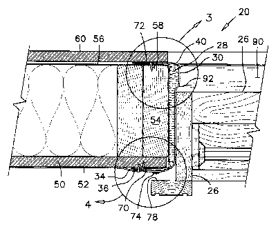
Referring firstly to FIGS. 1-7, the thermal insulation pad 20
according to the first preferred embodiment will be described. The thermal
insulation pad 20 is used to fill the gap space 22 between a wall opening 24
and a window frame 26. The thermal insulation pad 20 comprises a strip
of compressible insulation 28 such as fibreglass or batting insulation,
enclosed between a top and bottom strips of covering material. The top and
bottom strips of covering material are labelled as 30 and 32 respectively.
The preferred compressible insulation strip 28 has a rectangular
cross-section, a width 'A' corresponding to the wall thickness in which the
insulation pad is to be installed, normally 5-1/2 to 6 inches on modern
constructions, and an uncompressed thickness 'B' of about 3/4 of an inch.
The strips of covering material 30, 32 are preferably made of strong,
flexible, weather-resistant paper such as the type known in the construction
industry under the trade name TYPAR ~. It will be appreciated that
plastic or a flexible fabric material having weather-resistance properties can
also be used. Both strips of covering material 30, 32 are glued to the
compressible insulation strip 28 in a known manner.
The bottom cover strip 32 extends widthwise along one side of the
compressible insulation strip 28 to form a stapling flange 34. The top cover
strip 30 also extends widthwise along the same side to form a flashing
flange 36 over the stapling flange 34. Both the stapling flange 34 and the
flashing flange 36 are glued to each other along a bond line 38 having a
width 'C' of about one half inch, adjacent the insulation strip 28, as
illustrated in FIGS. 4, and 7. Both the stapling flange 34 and the flashing
flange 36 extend in a spaced-apart relationship from the bond line 38. The
bond line 38 provides a seal to prevent the infiltration of moisture into the
6
CA 02365140 2001-12-10
insulation strip 28, which moisture may occasionally seep between the
stapling flange 34 and the flashing flange 36. The top cover strip 30
extends widthwise along the other side of the compressible insulation strip
28 to form an interior flange 40.
The width 'D' of the stapling flange 34 and of the flashing flange
36, as well as the width 'E' of the interior flange are at least about 1-1/2
to
2 inches, such that these flanges can be wrapped around and over the sides
of the framing member 54, as illustrated in FIGS. 2-4.
In use, the stapling flange 34 is stapled to the exterior sheathing 50,
or to the outdoor side of the wall. The weather and air barrier 52 is inserted
between the stapling flange 34 and the flashing flange 36, and the flashing
flange 36 may also be stapled to the exterior sheathing 50. The top cover
strip 30 extends to enclose the compressible insulation strip 28 over the
wall stud 54, with the interior flange 40 extending over the interior vapour
1 S barrier 56. The interior flange 40 is also retained to the indoor side of
the
wall frame by means of staples 58. In conventional building constructions,
a wallboard 60 covers the interior flange 40. The sealing of the thermal
insulation pad 20 to the weather and air barrier 52 and to the interior vapour
barrier 56 prevents the infiltration of air along these barriers.
In order to further prevent the infiltration of air around a window or
a door frame, the stapling flange 34 preferably has an adhesive strip 70 on
its surface facing the flashing flange 36. This adhesive strip 70 is
preferably a type having a peeled-off protective paper strip, which is
removed during the installation of the thermal insulation pad 20.
7
CA 02365140 2001-12-10
A similar peeled-off adhesive strip 72 is also preferably affixed to
the inside surface of the interior flange 40 for the purpose of sealing the
interior flange to the vapour barrier 56. A bead of caulking 74 is applied
to the outside surface of the flashing flange 36 and is covered by a peeled-
off protective paper strip 76 until installation of the window or door frame
26 in the opening 24. The bead of caulking 74 is positioned to align with
the moulding 78 surrounding the window or door frame 26 for sealing the
window or door frame 26 to the flashing flange 36.
The thermal insulation pad 20 is preferably manufactured and sold
in lengths which are convenient for use without waste in the building
construction industry. It can also be manufactured and sold in rolls.
Referring to FIG. 5, an end flap 80 is preferably provided at one end
of the thermal insulation pad 20 to overlap an adjacent pad when joining
two pads end to end. Adhesive strips 82 are also preferably provided on the
end flap 80 to positively retain and seal two insulation pads to each other.
Referring now specifically to FIGS.1 and 6, the outside surface of
the top cover strip 30 has cut lines printed thereon for assisting in cutting
the insulation pad 20 to a proper length. The preferred cut lines comprises
transverse cut lines 84 extending perpendicular to the length of the pad 20
and diagonal cut lines 86 on the flashing flange 36, extending at a forty-
five degree angle with the length of the pad 20. The cut lines 84, 86 are
preferably spaced apart about one inch for convenience when using the
imperial measurement system.
Referring back to FIGS. 2-4, one advantage of the thermal
insulation pad 20 will be described with the aid of these drawings. As can
8
CA 02365140 2001-12-10
be appreciated, the top cover strip 30 encloses the compressible insulation
strip 28 completely and is anchored to both sides of the wall framing
member 54, as previously explained, thereby forming an elongated
cushioned liner 90 extending around and inside the wall opening 24. The
top cover strip 30 is in tension for being attached to both sides of the
framing member 54 and stretched by the compressible insulation strip 28
thereunder.
Because of this tensioning of the top cover strip 30 from the
compressible insulation strip, the top cover strip 30 does not tend to
wrinkle, grab or tear when the window or door frame is slid thereon. The
top cover strip 30 flexes smoothly as illustrated at label 92 in FIG. 2 ahead
of the window or door frame 26 being slid thereon. The compressibility of
the insulation strip 28 and the wrinkle free surface of the top cover strip 30
provide a cushioning characteristic which facilitates the sliding of a
window or door frame in a wall opening. After this installation, the
compressed insulation strip 28 provides a positive sealing of the gap space
22 between the window or door frame 26 and the wall opening 24.
Referring now to FIG. 8, there is illustrated therein a thermal
insulation pad 100 according to the second preferred embodiment of the
present invention. In this second preferred embodiment, the compressible
insulation strip 28 is only partly enclosed by a top cover strip 102 and a
bottom cover strip 104. Both cover strips are made of strong weather
resistant construction paper such as previously described, and jointly extend
along one side of the insulation strip 28 to form a stapling flange 106. It
will be appreciated that in use, when the stapling flange 106 is affixed to
the outside surface of a wall, the top cover strip 102 is subjected to
tensioning forces when a window or door frame is slid thereon. These
9
CA 02365140 2001-12-10
tensioning forces provide to a certain extent, the advantages as previously
described in guiding a window or door frame 26 thereon without wrinkling,
grabbing or tearing.
Several features of the first preferred embodiment 20, such as a bead
of caulking, cutting lines or an end flap may be provided on this second
preferred embodiment 100 to obtain the advantages as previously
described.
Referring now to FIGS. 9 and 10, the thermal insulation pad 110
according to the third preferred embodiment is illustrated therein. This
thermal insulation pad has a length corresponding to the inside height in a
wall opening 112 adapted to receive a door frame. This thermal insulation
pad 110 has transverse notches 114 therein where both the top and bottom
cover strips 30, 32 are cut out between the stapling and flashing flanges 34,
36, and the interior flange 40. Each transverse notch 114 extends the full
depth of the insulation strip 28. Otherwise, the thermal insulation pad 110
according to the third preferred embodiment is constructed in a similar
manner as the thermal insulation pad 20 according to the first preferred
embodiment, and may have all the features of this first preferred
embodiment.
The purpose of the transverse notches 114 is to provide shimming
pockets 116 which extend down to the surface of the framing member 112,
for shimming a door frame for example. The notches 114 are preferably
spaced apart such as to provide shimming pockets under the hinges of a
door. For example, a thermal insulation pad 110 for a 79 inch door would
have a first notch 114 at 9-1/2 inches from the lower end thereof, and at
every 15-1/2 inches thereafter, as shown by label 'F'. This notch spacing
CA 02365140 2001-12-10
provides shimming pockets 116 behind a set of hinges spaced at a
conventional spacing of 31 inches.
Similar notches 114 can be precut into the thermal insulation pads
according to the first or second preferred embodiments for accommodating
shims, latches, tie straps, etc in the gap space 22. The pockets 116 formed
by the transverse notches 114 are insulated in a conventional manner with
loose insulation after the installation of the door or window in the wall
opening.
When the thermal insulation pad 110 is sold as a general purpose
door insulation product wherein a quantity of shim pockets 116 and pocket
spacings are provided for a variety of door sizes and weights, some or all
of the transverse notches 114 are preferably covered by patches 118 and
exposed only if needed. The preferred patch 118 consists of a plug 120 of
compressible insulation material affixed to a flexible tape material 122
having peeled-off adhesive properties. The flexible tape 122 is removably
bonded to the top covering strip 30, covering a respective notch 114
completely without discontinuity in the insulation material 28.
As to other manner of usage and operation of the present invention,
the same should be apparent from the above description and accompanying
drawings, and accordingly further discussion relative to the manner of
usage and operation of the invention would be considered repetitious and
is not provided.
While one embodiment of the present invention has been illustrated
and described herein above, it will be appreciated by those skilled in the art
that various modifications, alternate constructions and equivalents may be
11
CA 02365140 2001-12-10
employed without departing from the true spirit and scope of the invention.
Therefore, the above description and the illustrations should not be
construed as limiting the scope of the invention which is defined by the
appended claims.
12