Language selection

Search

Patent 2365234 Summary

Third-party information liability

Some of the information on this Web page has been provided by external sources. The Government of Canada is not responsible for the accuracy, reliability or currency of the information supplied by external sources. Users wishing to rely upon this information should consult directly with the source of the information. Content provided by external sources is not subject to official languages, privacy and accessibility requirements.

Claims and Abstract availability

Any discrepancies in the text and image of the Claims and Abstract are due to differing posting times. Text of the Claims and Abstract are posted:

  • At the time the application is open to public inspection;
  • At the time of issue of the patent (grant).
(12) Patent Application: (11) CA 2365234
(54) English Title: LIGHT SOURCE
(54) French Title: SOURCE DE LUMIERE
Status: Deemed Abandoned and Beyond the Period of Reinstatement - Pending Response to Notice of Disregarded Communication
Bibliographic Data
(51) International Patent Classification (IPC):
  • F21V 7/06 (2006.01)
  • F21S 8/00 (2006.01)
  • F21V 7/00 (2006.01)
  • F21V 7/09 (2006.01)
(72) Inventors :
  • EBIKO, NAOKI (Japan)
(73) Owners :
  • FUJITSU GENERAL LIMITED
(71) Applicants :
  • FUJITSU GENERAL LIMITED (Japan)
(74) Agent: GOWLING WLG (CANADA) LLP
(74) Associate agent:
(45) Issued:
(86) PCT Filing Date: 2001-01-19
(87) Open to Public Inspection: 2001-07-26
Availability of licence: N/A
Dedicated to the Public: N/A
(25) Language of filing: English

Patent Cooperation Treaty (PCT): Yes
(86) PCT Filing Number: PCT/JP2001/000345
(87) International Publication Number: WO 2001053743
(85) National Entry: 2001-09-18

(30) Application Priority Data:
Application No. Country/Territory Date
2000-11261 (Japan) 2000-01-20

Abstracts

English Abstract


For efficient use of light from a light source (1), a reflector (2) comprises
a first paraboloid (3) (a, b) for reflecting the light from the light source
(1) to form rays of light parallel to an optical axis (6),?a second paraboloid
(4) (b, c) for reflecting the light from the light source (1) to form parallel
rays of light deviating outside, and a bottomless frustum (5) (a-d) of a cone
for reflecting the light from the second paraboloid (4) to form rays of light
parallel to an optical axis (6). Despite the light source (1) in front of it,
the reflector is capable of forming rays of light parallel to the optical axis
(6).


French Abstract

Pour avoir une utilisation efficace de la lumi­re provenant d'une source de lumi­re (1), un r~flecteur (2) comprend un premier parabolo~de (3) (a, b) destin~ ~ r~fl~chir la lumi­re provenant de la source de lumi­re (1) pour former des rayons de lumi­re parall­les ~ un axe optique (6), un second parabolo~de (4) (b, c) destin~ ~ r~fl~chir la lumi­re provenant de la source de lumi­re (1) pour former des rayons de lumi­re parall­les d~viant ~ l'ext~rieur, et un tronc (5) (a-d) sans fond d'un cÙne destin~ ~ r~fl~chir la lumi­re provenant du second parabolo~de (4) pour former des rayons de lumi­re parall­les ~ un axe optique (6). Bien que la source de lumi­re (1) se trouve devant lui, le r~flecteur est capable de former des rayons de lumi­re parall­les ~ l'axe optique (6).

Claims

Note: Claims are shown in the official language in which they were submitted.

7
CLAIMS
1. An illumination light source unit, wherein a reflector, designed for
outputting parallel light rays by reflecting the light rays emitted by the
light-emitting part of a light source lamp, comprises a first parabolic
reflector having a parabolic surface with a focal point coincident with the
center of the light emitting part and being formed centering around the
optical axis but not including the portion corresponding to the external
contour of the light source lamp in order to reflect the light rays coming
from
the light source lamp, a second parabolic reflector forming a portion not
included in the first parabolic reflector and having a parabolic surface with
a
focal point eccentric from the center of the light-emitting part of the light
source lamp in order to reflect the light rays coming from the light-emitting
part of the light source lamp towards the direction of the rim of the opening
of the first parabolic reflector, and a bottomless circular truncated conic
reflector formed on the rim of the opening of the first parabolic reflector in
order to reflect the light rays reflected by the second parabolic reflector in
the direction parallel to the optical axis.
2. An illumination light source unit according to claim 1, wherein the
first parabolic reflector, the second parabolic reflector and the circular
truncated conic reflector are formed as an integral part.
3. An illumination light source unit according to claim 1, wherein the
first parabolic reflector and the second parabolic reflector are formed as an
integral part, while the circular truncated conic reflector is formed
separately
to be mounted on the rim of the opening of the first parabolic reflector.
4. An illumination light source unit according to claim 1, claim 2 or claim

8
3, wherein a dichroic film capable of reflecting only the visible light rays
is
provided over the reflecting surface of each of the first parabolic reflector,
the second parabolic reflector and the circular truncated conic reflector.
5. An illumination light source unit according to claim 3, wherein each of
the reflecting surfaces of the first parabolic reflector and the second
parabolic is provided with a dichroic film capable of reflecting only the
visible light rays, while the reflecting surface of the circular truncated
conic
reflector is provided with a metallic reflecting film.
6. An illumination light source unit according to claim 3, wherein the
dichroic reflecting film capable of reflecting only the visible light rays is
formed over each of the reflecting surfaces of the first parabolic reflector
and
the second parabolic reflector, while the circular truncated conic reflector
is
composed of an aluminum reflector.
7. An illumination light source unit according to claim 3, wherein the
first parabolic reflector and the second parabolic reflector are formed from
the glass and the reflecting surfaces thereof are provided with the dichroic
films capable of reflecting only the visible light rays respectively, while
the
circular truncated conic reflector is formed as an aluminum reflector.

Description

Note: Descriptions are shown in the official language in which they were submitted.


CA 02365234 2001-09-18
1
TECHNICAL FIELD
The present invention relates to an illumination light source unit to be
used for the liquid crystal projector and the like and designed for efficient
reflection of the light rays.
BACKGROUND ART
In the case of the illumination light source unit to be used for the liquid
crystal projector, a light source lamp is placed at the focal point of a
parabolic reflector so that the light rays emitted from the light source lamp
are reflected by the parabolic reflector to be outputted as parallel right
rays.
However, the light rays reflected near the optical axis (near the base of the
light source lamp) is diffracted by being reflected by the surface of a
spherical lamp due to the effect of the shadow of the light source lamp, so
that the diffracted light rays cannot be used effectively as parallel light
rays.
The present invention is intended to dissolve such problem of the prior art
and designed for increasing the luminance of the projected picture by
converting into parallel rays the light rays reflected near the optical axis
of
the parabolic reflector of the illumination light source, thereby improving
the
utilization rate of the light source.
DISCLOS rR OF H INV NTT(1N
The present invention is intended to resolve the above-mentioned problem
and wherein the reflector of the illumination light source unit according to
the present invention comprises a first parabolic reflector, for reflecting
the
light rays coming from the light source lamp, having a paraboloid with a

CA 02365234 2001-09-18
2
focal point coincident with the center of the light-emitting part of the light
source and forming a portion of the reflector not including the portion
corresponding to the external contour of the light source lamp with respect to
the optical axis as being the center thereof, a second parabolic reflector
forming the portion of the reflector, for reflecting the light coming from the
light source lamp towards the rim of the opening of the first parabolic
reflector, not including the first parabolic reflector but including a
paraboloid having a focal point eccentric from the center of the light-
emitting
part of the light source lamp, and a bottomless circular truncated conic
reflector so that the light rays from the light source are reflected to become
parallel light rays to be outputted.
The first parabolic reflector, the second parabolic reflector and the
circular truncated conic reflector may be formed as an integral part, or the
circular truncated conic reflector alone may be formed separately to be
1 5 mounted on the rim of the opening of the first parabolic reflector.
All the reflecting surfaces of the first parabolic reflector, the second
parabolic reflector and the circular truncated conic reflector may be provided
with a dichroic reflecting film capable of reflecting only the visible light
rays
respectively, or the reflecting surfaces of both the first parabolic reflector
ZO and the second parabolic reflector may be provide with a dichroic
reflecting
film capable of reflecting only the visible light rays while the reflecting
surface of the circular truncated conic reflector may be provided with a
metallic reflecting film or may be made into a total reflector provided with
an
aluminum reflecting surface. When providing the circular truncated conic
2 5 reflector as a total reflection reflector, it is preferable to be farmed
independently for the ease of forming process.
Further, the first parabolic reflector and the second parabolic reflector
may be formed of the glass, and the reflecting surfaces thereof may be
provided with a dichroic reflecting film capable of reflecting only the
visible

CA 02365234 2001-09-18
3
light rays respectively.
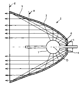
Fig. 1 is a sectional view showing the principal parts of the illumination
light source unit as an embodiment of the present invention.
Fig. 2 is another sectional view showing the principal parts of the
illumination light source unit as another embodiment of the present
invention.
BEST MODE FOR CARRYING OUT TH . INVENTION
An embodiment of the present invention will be described below referring
to Fig. 1.
In Fig. 1, the numeral 1 represents the light source lamp; 2, the reflector;
6, the optical path. The reflector 2 comprises the first parabolic reflector 3
(portion ranging from line a to line b), the second parabolic reflector 4
(portion ranging from line b to line c), the bottomless circular truncated
conic reflector 5 (portion ranging from line a to line d), which are formed as
an integral part.
The first parabolic reflector 3 comprises a portion corresponding to the
external contour of the light source lamp 1, that is, the portion ranging from
the line a to line b, not including the second parabolic reflector 4, so that
the
internal surface (reflecting surface) thereof constitutes a paraboloid with
its
focal point coincident with the center of the light-emitting part of the light
source lamp 1. However, the first parabolic reflector 3 is composed of a
2 5 paraboloid of revolution with its axis coincident with the central axis of
the
parabola. The reflecting surface is provided with the dichroic film capable
of reflecting only the visible light rays.
The second parabolic reflector 4 is composed of a portion ranging from
the line b to line c corresponding to the external contour of the of the light

CA 02365234 2001-09-18
4
source lamp 1 having an optical axis 6 and an internal surface formed of a
paraboloid having its focal point coincident with the center of the light-
emitting part of the light source lamp 1.
However, the second parabolic reflector 4 is composed of a paraboloid of
revolution formed with respect to the line between the apex of the parabola
and the eccentric focal point so that the optical axis is inclined towards the
outside at an angle at which the light rays from the light source lamp 1 is
reflected in the direction of the circular truncated conic reflector 5.
The reflecting surface is provided with a dichroic film, which is similar to
one provided to the first parabolic reflector 3.
The circular truncated conic reflector 5 comprises a bottomless circular
truncated conic internal surface formed along the rims a through d at the
opening of the first parabolic reflector 3 so that the parallel light rays
reflected by the second parabolic reflector 4 are reflected in the direction
parallel to the optical axis 6. The reflecting surface is provided with a
dichroic film, which is similar to one provided to the first parabolic
reflector
3.
Next, the illumination light source unit having the composition as is
discussed above will be described in the following.
The light rays from the light source lamp 1 are radially propagated to fall
on various parts of the reflector 2. Of the light rays falling on the second
parabolic reflector 4, only the visible light rays are reflected in the
direction
parallel to the optical axis 6 for being outputted. Of the light rays striking
the second parabolic reflector 4, only the visible light rays are reflected
2 5 towards the circular truncated conic reflector 5 so that the light rays
are
reflected by the circular truncated conic reflector 5 in the direction
parallel
to the optical axis 6 for being outputted. In this fashion, all the visible
light rays emitted from the light source lamp 1 and reflected by the reflector
2 are outputted as the light rays parallel to the optical axis 6.

CA 02365234 2001-09-18
Next, another embodiment of the present invention will be described
below referring to Fig. 2.
The embodiment shown in Fig. 2 is substantially similar to the
embodiment shown in Fig. 1. The embodiment shown in Fig. 2, however,
5 differs from that shown in Fig. 1 in that the circular truncated conic
reflector
5 is formed separately from the first parabolic reflector 3 and the second
parabolic reflector 4 which are formed integrally, and mounted on the rim of
the opening of the first parabolic reflector 3 to form the reflector 2.
The function of the embodiment shown in Fig. 2 will be omitted here,
since its function is similar to that of the embodiment shown in Fig. 1.
For the embodiments shown in Fig. 1 and Fig. 2 respectively, the
materials from which the reflectors 3, 4 and S are to be formed are not
mentioned, but various kinds of synthetic resins, metals such as the aluminum
and the glass may be used.
In each of the embodiments discussed previously, the dichroic film
capable of reflecting only the visible light rays against the reflecting
surfaces
of the reflectors 3, 4 and 5, but the present invention is not limited to
these
embodiments; for instance, the reflecting surface of the circular truncated
conic reflector 5 may be provided with a metallic total reflection film.
Further, the circular truncated conic reflector 5 may be an aluminum reflector
(total reflector). This is because the light rays reflected by the second
parabolic reflector 4 to fall on the circular truncated conic reflector 5 have
been reduced to the visible rays by the dichroic film formed over the
reflecting surface of the second parabolic reflector 4. In this case, it is
2 5 easier for the fabrication to form the circular truncated conic reflector
5
separately, so that the embodiment shown in Fig. 2 is preferable.
As discussed in the foregoing, with the illumination light source unit

CA 02365234 2001-09-18
6
according to the present invention, it becomes possible to output the light
rays in the shadow of the spherical light source lamp as parallel light rays
for
the effective use of the light rays from the light source, thereby enabling
the
light source unit to be used for the liquid crystal projector which requires
the
light source unit capable of providing a higher luminance.

Representative Drawing
A single figure which represents the drawing illustrating the invention.
Administrative Status

2024-08-01:As part of the Next Generation Patents (NGP) transition, the Canadian Patents Database (CPD) now contains a more detailed Event History, which replicates the Event Log of our new back-office solution.

Please note that "Inactive:" events refers to events no longer in use in our new back-office solution.

For a clearer understanding of the status of the application/patent presented on this page, the site Disclaimer , as well as the definitions for Patent , Event History , Maintenance Fee  and Payment History  should be consulted.

Event History

Description Date
Inactive: IPC expired 2016-01-01
Application Not Reinstated by Deadline 2007-01-19
Time Limit for Reversal Expired 2007-01-19
Inactive: IPC from MCD 2006-03-12
Inactive: Abandon-RFE+Late fee unpaid-Correspondence sent 2006-01-19
Deemed Abandoned - Failure to Respond to Maintenance Fee Notice 2006-01-19
Letter Sent 2002-02-05
Inactive: Notice - National entry - No RFE 2002-02-05
Inactive: Cover page published 2002-02-04
Inactive: First IPC assigned 2002-01-31
Application Received - PCT 2002-01-18
Application Published (Open to Public Inspection) 2001-07-26

Abandonment History

Abandonment Date Reason Reinstatement Date
2006-01-19

Maintenance Fee

The last payment was received on 2004-12-22

Note : If the full payment has not been received on or before the date indicated, a further fee may be required which may be one of the following

  • the reinstatement fee;
  • the late payment fee; or
  • additional fee to reverse deemed expiry.

Please refer to the CIPO Patent Fees web page to see all current fee amounts.

Fee History

Fee Type Anniversary Year Due Date Paid Date
Basic national fee - standard 2001-09-18
Registration of a document 2001-09-18
MF (application, 2nd anniv.) - standard 02 2003-01-20 2002-12-23
MF (application, 3rd anniv.) - standard 03 2004-01-19 2003-12-22
MF (application, 4th anniv.) - standard 04 2005-01-19 2004-12-22
Owners on Record

Note: Records showing the ownership history in alphabetical order.

Current Owners on Record
FUJITSU GENERAL LIMITED
Past Owners on Record
NAOKI EBIKO
Past Owners that do not appear in the "Owners on Record" listing will appear in other documentation within the application.
Documents

To view selected files, please enter reCAPTCHA code :


To view images, click a link in the Document Description column. To download the documents, select one or more checkboxes in the first column and then click the "Download Selected in PDF format (Zip Archive)" or the "Download Selected as Single PDF" button.

List of published and non-published patent-specific documents on the CPD .

If you have any difficulty accessing content, you can call the Client Service Centre at 1-866-997-1936 or send them an e-mail at CIPO Client Service Centre.


Document
Description 
Date
(yyyy-mm-dd) 
Number of pages   Size of Image (KB) 
Representative drawing 2001-09-18 1 10
Cover Page 2002-02-04 1 39
Claims 2001-09-18 2 66
Description 2001-09-18 6 208
Abstract 2001-09-18 1 23
Drawings 2001-09-18 1 18
Notice of National Entry 2002-02-05 1 193
Courtesy - Certificate of registration (related document(s)) 2002-02-05 1 113
Reminder of maintenance fee due 2002-09-23 1 109
Reminder - Request for Examination 2005-09-20 1 116
Courtesy - Abandonment Letter (Maintenance Fee) 2006-03-16 1 174
Courtesy - Abandonment Letter (Request for Examination) 2006-03-30 1 166
PCT 2001-09-18 3 125
Fees 2002-12-23 1 29
Fees 2003-12-22 1 31
Fees 2004-12-22 1 32