Note: Descriptions are shown in the official language in which they were submitted.
CA 02365538 2004-07-27
1
DISPOSABLE MICROKERATOME BLADE HOUSING
BACKGROUND OF THE INVENTION
Field of Invention
The present invention relates generally to surgical instruments and in
particular
to instruments for surgery of the eye.
More particularly, the present invention relates to medical instruments used
for
lamellar keratotomy, known as microkeratomes.
Specifically, the present invention is an improvement to existing,
microkeratomes in that the invention is disposable thereby replacing the
permanent
cutting head portion of the existing instruments and increasing the efficiency
of the
microkeratome by increasing the efficiency of operations through the
elimination of
timely de-contamination procedures on current microkeratomes.
Description of the Prior Art
In the field of eye surgery generally, and in the field of keratectomy
specifically, a number of devices called microkeratomes have been developed.
The
microkeratome surgical instrument is used to perform lamellar keratotomy.
During the
lamellar keratotomy operation, the instrument produces a thin section of the
cornea, on
which further surgery may be performed. In order to produce the thin section,
the
instrument must be moved across the ocular globe or eye. The microkeratome
excursion may be linear or rotational across the ocular globe. In order to
move the
instrument a number of means have been utilized including manual, a track and
gears
or through use of a keyed pivot sweeping the instrument through an arc.
CA 02365538 2001-09-13
WO 00/56222 PCT/EP00/02643
2
Microkeratomes are comprised of numerous delicate and precision parts. In
general, these medical instruments typically differ in their configuration,
although
having a number of common features. The common features include a vacuum ring
to
securely grip the ocular globe, a cutting head that includes a plaque and
knife edged
blade to compress and cut the ocular globe, and a motor/gearing combination
that both
oscillates the blade and moves the instrument over a given path with respect
to the
ocular globe.
One co~guration in the prior art discloses a microkeratome assembled such
that the motor and gearing are directly connected and combined in a common
housing
or a permanently attached individual housing. The motor and gearing unit is
then
permanently attached to a cutting head which accommodates the blade. Another
configuration disclosed in the prior art utilizes the common features of a
motor/gearing
combination but accommodates the components in separable housings. Separate
accommodations for the motor and gearing requires the combination of the
gearing
and blade in the cutting head. Each of the configurations described have their
individual disadvantages and some common problems.
The configuration uniting the gearing with the motor in a single housing with
a
permanent attachment to the cutting head also includes a cutting head designed
to
allow access and removal of the blades. Although the cutting head can be
opened to
replace the blades, the surface through which the blade protrudes for
providing cutting
is hinged but does not detach from the cutting head. Since the instrument is
ostensibly
a single unit with motor, gearing, and cutting head, after each use the entire
instrument
must endure a sterilization process. Due to the delicate and intricate nature
of the
instrument, sterilization can be deleterious to the precision gearing and
electronics.
Therefore the importance of the elimination or reduction in the number of
sterilizations
is apparent.
Separation of the gearing and motor does not completely solve the instrument
sterilization problem. Combining the gearing and cutting head into a removable
unit
obviates the need to process the motor and electronics with the well known
methods of
sterilization; however, the complexity and size of the cutting head is
increased. In
addition, the amount of space available around the ocular globe is limited and
SUSSTmJTE SHEET (RULE 2~)
CA 02365538 2001-09-13
w0 00/56222 PCT/EP00/02643
3
restricted by the patient's anatomy. Thus, while the life of the motor and
electronics
may be extended, some patients may not be able to accommodate the size of the
instrument. Also, unless the entire cutting head assembly is discarded after
use, which
may be cost prohibitive, the delicate precision gearing is exposed to the
sterilization
process after each use.
Another consideration fundamental to this type of surgery is the integrity or
quality of the cut. Discontinuities or aberrations in the shape of the cut can
have
serious ramifications on the post-operative vision of the patient. Prior art
discloses
microkeratomes with characteristics negatively affecting the quality or
integrity of the
cut. Some of the negative characteristics are poor material properties and
compliance,
or lack of rigidity of the assembled instrument. The construction of
microkeratome
components from such materials with unacceptable properties can result in
degraded
performance for a variety of reasons including dimensional instability.
Dimensional
instability, such as warping of the cutting head, allows the blade to move in
an
unplanned manner, which results in an unintended cut shape. Excessive
compliance of
the assembled microkeratome may result in unintended excursion from the
desired path
over the ocular globe. Consequently with diminished control of the cutting
instrument
the quality of the cut is compromised.
In response to the shortcomings described herein, it is a feature of the
present
invention to provide an improvement to existing microkeratomes wherein the
disposable blade housing is independent of the motor, gearing, and cutting
head of the
microkeratome.
It is another feature that the disposable blade housing improves existing
microkeratomes by remaining dimensionally stable, damping vibration and
resisting
deflection while maintaining the quality of the cut.
It is a further feature that the disposable blade housing improves on existing
microkeratome requirements of pre-operative assembly of the instrument.
It is a still further feature that the disposable blade housing improves on
the
existing microkeratome requirements for sterilization and contamination
potential of
the surgery.
SUBSTITUTE SHEET (i~Ul-E 2B)
CA 02365538 2001-09-13
WO 00/56222 PCT/EP00/02643
4
It is a further feature that the disposable blade housing improves existing
microkeratome requirements by providing the disposable blade housing in a
limited
number of components, such that the overall number of parts are eliminated.
It is a further feature of the invention that the disposable blade housing is
composed of materials to reduce the cost of the overall procedure.
Summary of the Invention
The present invention is drawn to a disposable microkeratome for attachment
to a guide ring secured to an ocular globe to perform lamellar keratotomy. The
microkeratome has a blade assembly with a cutting edge. A cutting head is
adapted to
join to the guide ring and move in a plane substantially parallel to a surface
of the guide
ring. The cutting head has an integral compression surface for compressing the
ocular
globe and a blade slot adjacent the compression surface. The cutting head
closely
receives the blade assembly such that the cutting edge protrudes through the
blade slot
toward the compression surface and the blade assembly is restrained to move
substantially only along one axis. A motor is releasably attached to the
cutting head to
oscillate the blade assembly along the one axis.
The cutting head has a lower portion releasably joined to an upper portion and
the blade assembly is held between the upper portion and the lower portion.
The
upper portion has a longitudinal key and the lower portion has a longitudinal
keyway
adapted to receive the longitudinal key of the upper portion to hold the upper
portion
and lower portions together. The upper portion has a protrusion and the lower
portion
has an opening adapted to receive the protrusion and laterally restrain the
lower
portion with respect to the upper portion. The lower portion is made from a
material
that is more flexible than the material of the upper portion. The lower
portion is a
material selected from the group consisting of polymeric, composite, and
ceramic
materials. The cutting head has an overall height dimension and a height of
the lower
portion is less than one third the overall height dimension. The lower portion
is
located within two lower portion height dimensions of a point at which the
lower
SUBSTITUTE SHEET (RULE ~6)
CA 02365538 2001-09-13
WO 00/56222 PCT/EP00/02643
S
portion joins the guide ring. The motor rotates a pin about a central axis and
a blade
assembly has a slot that receives the pin.
The invention also encompasses a method of performing lamellar keratotomy
on an ocular globe including providing a microkeratome having an upper
portion, a
lower portion, and a blade. A guide ring is secured to the ocular globe and
the
microkeratome is joined to the guide ring. The microkeratome is moved across
the
guide ring to contact the blade with and cut the ocular globe. The
microkeratome is
removed from the guide ring and the lower portion and blade are disposed of.
Then, a
fresh unused lower portion and blade are joined to the upper portion.
Brief Description of the Drawings
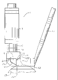
FIG. 1 is a side view of a microkeratome with the first embodiment of the
present invention wherein the cutting head and disposable blade housing are
separate
components.
FIG. 2 is side view of a second embodiment of the present invention wherein
the disposable blade housing and cutting head are a single component.
FIG. 3 is an superior exploded view of the first embodiment of the invention,
shown together with the blade holder and motor.
FIG. 4 is an inferior exploded view of the first embodiment of the invention
with the blade holder and motor.
FIG. 5 is an inferior exploded view of the second embodiment of the invention.
FIG. 6 is a front view of the disposable blade housing of the first
embodiment.
FIG. 7 is a rear view of the disposable blade housing of the first embodiment.
Detailed Description of the Preferred Embodiments
In a first embodiment of the invention as seen in Figs. 1,3 and 4,
microkeratome I comprises motor 3, cutting head S, disposable blade housing 7,
blade
SUBSTITUTE SHEET (RULE 26)
CA 02365538 2001-09-13
WO 00/56222 PCT/EP00/02643
6
holder 9 and blade 11. Microkeratome 1 is engaged with guide ring 13 which
surrounds ocular globe 15. The coupling of guide ring 13 and disposable blade
housing 7 during actuation of microkeratome l, typically composed of a gear
and track
system, is not shown. Other well-known coupling means may be employed during
actuation of microkeratome 1 that are also not shown. Vacuum 17 is used to
maintain
ocular globe 15 above the plane of guide ring 13 for correct positional
alignment with
blade 11 for incision.
Cutting head 5 has threaded portion 19 for engagement with motor 3.
Disposable blade housing 7 is interchangeably attached to cutting head 5 by a
first and
second longitudinal keyway 21, 23 located on superior portion 25 of disposable
blade
housing 7, which are respectively adapted to receive a first and second
longitudinal key
27, 29 located on the inferior portion 31 of cutting head S. Cutting head 5
has an axial
opening 33 for receiving axial shaft 34 of motor 3.
Blade 11 has trapezoidal shape, the base 35 of which projects angularly
outward from blade holder 9 towards portion of ocular globe above the plane of
guide
ring for incision during actuation of microkeratome. Blade 11 and blade holder
9 are
closely received in housing 7 to move substantially along only one axis. A
cutting edge
of blade 11 extends through a blade slot 12 in housing 7 toward plaque 51
described in more detail below. Cutting head 5 has cylindrical projection 37
to further
engage disposable blade housing 7. Disposable blade housing 7 has a
cylindrical
opening 39 to mate with cylindrical projection 37 of cutting head 5. Opening
39 may
also be adapted to receive a pin (not shown) extending upward from guide ring
13 to
allow the apparatus to rotate the plane of ring 13.
Now referring to Figures 3 and 4, axial shaft 34 of motor 3 terminates outside
blade holder 9 in small eccentric projection or pin 41. Eccentric pin 41
engages slot 43
of blade holder 9 through internally threaded portion 19 of cutting head 5 to
transmit
an oscillatory motion to blade 11 that corresponds to the speed of the motor
3. Motor
3 has corresponding threaded portion 45 for engagement with cutting head 5.
Axial
opening 33 of cutting head permits extension of axial shaft 34 therethrough.
The
eccentric pin 41 secures blade holder 9 loosely between cutting head 5 and
disposable
blade housing 7. Blade holder 9 thus oscillates freely in direct relation with
axial shaft
SUBSTITUTE SHEET (RULE 26)
CA 02365538 2001-09-13
w0 00/56222 PCT/EP00/02643
7
19 and is held such that lateral movement of the blade holder 9 is permitted.
On the
advancing face 47 of disposable blade housing 7 is an elliptical opening 49.
Elliptical
opening 49 defines plaque 51 that compresses and maintains ocular globe 15 at
a
predetermined pressure for incision thereto during actuation of microkeratome
1 as can
be seen in Fig. 5.
Figs. 2 and 5 show microkeratome 53 in a second embodiment of the present
invention. In this embodiment, microkeratome 53 comprises motor 55, disposable
blade housing 57, blade holder 59 and blade 61. Microkeratome 53 is engaged
with
guide ring 63 which surrounds ocular globe 65 in the same manner as in the
first
embodiment. Vacuum 67 is used to maintain ocular globe 65 above the plane of
the
guide ring 63 for correct positional alignment with blade 61 for incision.
Disposable blade housing 57 is adapted to receive blade holder 59 which has
blade 61 fixedly attached thereto such that blade 61 and holder 59 move
substantially
only along one axis. Blade 61 is trapezoidal with the cutting edge 68 of blade
61
projecting angularly outward from disposable blade housing 57 through blade
slot 58
toward plaque 83 and a portion of ocular globe 65 above the plane of guide
ring 63.
Superior threaded portion 69 of disposable blade housing 57 is adapted to
receive
corresponding threaded portion 71 from motor 55. Disposable blade housing 57
has
axial opening 73 in alignment with axial shaft 75 of motor 55. As in the first
embodiment, axial shaft 75 of motor 55 terminates in eccentric pin 77, which
engages
slot 79 of blade holder 59 and secures blade holder 59 within disposable blade
housing
57. Operation of motor 55 oscillates blade holder 59 and blade 61 during
actuation of
microkeratome 53.
As in the first embodiment, during actuation of microkeratome 53 across a
predetermined cutting path, disposable blade housing 57 has plaque 81 formed
by
elliptical opening 83 that compresses and maintains ocular globe 65 at a
predetermined
pressure for incision thereto.
The microkeratome blade housing of the present invention includes a lockable
and releasable coupling capable of snap tight fit between the disposable blade
housing
and the remaining part of a microkeratome. The coupling provides a self
positioning
and secure placement of the disposable blade housing onto the medical
instrument such
SUBSTITUTE SHEET (RUSE 26)
CA 02365538 2004-07-27
g
that once the disposable blade housing is in place there is no relative
movement
between the medical instrument and the disposable blade housing.
The disposable blade housing includes structure capable of transmitting forces
from the motor and gearing to the blade. The transmitted forces induce a
reciprocating
or oscillating motion on the blade. The blade is constrained to oscillate or
reciprocate in
the direction transverse to the direction of motion of the microkeratome.
Overall
structural rigidity of the instrument is maintained by the disposable blade
housing
height dimension being preferably less than one third the overall height
dimension of
the assembled microkeratome. Positioning of the disposable blade housing is
also
controlled. The disposable blade housing is preferably located within two
disposable
blade housing height dimensions from the means that carnes the cutting head
with
respect to the guide ring. Locating the disposable blade housing in close
proximity to
the movement means reduces potential for physical interference and unintended
distorted excursion of the microkeratome due to the disposable blade housing.
The disposable blade housing also includes a plaque, which is the portion of
the
blade housing directly in front of the blade. The plaque functions to
partially compress
the oculai globe immediately before contact by the blade, thereby regulating
the depth
and shape of incision.
In a preferred embodiment of the present invention the disposable blade
housing
is fabricated from a polymeric, composite or ductile ceramic material. The
material
must be flexible enough to be formed into a self positioning, locking and
releasable
structure. The material of the disposable blade housing must also be capable
of
damping vibrations, maintaining dimensions, resisting deflections, and
maintaining
rigidity in order to produce a cut of satisfactory quality. TeflonT'M is an
example of an
acceptable polymeric material. TeflonTM has an additional benefit of being
self
lubricating, thereby eliminating the need for lubricants and decreasing the
possibility of
failure or binding of the moving parts. The plaque may be adjustable or non-
adjustable.
The plaque as shown in the drawings is not adjustable and may be of the type
that
provides a single predetermined shape and thickness of cut by the cutting
blade.
CA 02365538 2001-09-13
WO 00/56222 PCT/EP00/02643
9
In use, a guide ring is joined to an ocular globe and the microkeratome is
joined
to the guide ring to rotate across a plane substantially parallel to the top
surface of the
guide ring. The motor is actuated to oscillate blade and the microkeratome is
moved
across the guide ring to cut the ocular globe. When the procedure is complete,
the
microkeratome is removed and the blade housing, blade holder, and blade are
disposed of. The motor and cutting head are retained for reuse. In an
embodiment as
depicted in Figs. 2 and 5, the entire blade housing, blade holder, and blade
are disposed
of. The remaining components of the microkeratome are cleaned and fresh,
unused
components are reattached.
While the invention has been shown in only two of its forms, it should be
apparent to those skilled in the art that it is not so limited, but is
susceptible to various
changes without departing from the scope of the invention.
In the present specification "comprise" means "includes or consists of and
"comprising" means "including or consisting oF'.
The features disclosed in the foregoing description, or the following claims,
or
the accompanying drawings, expressed in their specific forms or in terms of a
means
for performing the disclosed function, or a method or process for attaining
the
disclosed result, as appropriate, may, separately, or in any combination of
such
features, be utilised for realising the invention in diverse forms thereof.
SURS~TUTE SHEET (RULE 26)