Note: Descriptions are shown in the official language in which they were submitted.
CA 02365621 2001-09-27
WO 01/55696 PCT/CA01/00091
1
APPARATUS AND METHOD FOR MEASURING THE RHEOLOGICAL
PROPERTIES OF A POWER LAW FLUID
The invention is concerned with an apparatus and a method for measuring the
rheological properties of a Newtonian or a non-Newtonian fluid exhibiting a
power law
behavior in a tube and which is flowing in a laminar manner. This invention
allows the
consistency index (k) and the power law index (n) to be known in real time. It
also
improves the mixing of the fluid and maintains its homogeneity.
In many industrial processes, the quality of final products depends on several
key
physical properties, such as density, temperature, pressure, flow rate, pH,
solid
concentration, flow characteristics and others. These physical properties and
their
evolution need to be monitored and kept within given limits so as to maintain
or even
enhance the quality and constancy of the final products. Yet, knowing the
physical
properties in real time is essential in a fully automated process to provide
an
adequate feedback to the control system in which the target values of the
parameters
have been programmed. If necessary, the control system changes the amounts of
ingredients or adjusts the various settings while the process is underway.
Among the physical parameters to monitor, the ones related to the flow
characteristics of the materials are particularly important in a wide range of
applications. Knowing the flow characteristics is the prime interest of the
science of
rheology. One of the key parameters in rheology is the viscosity, which may be
roughly defined as the resistance to the flow of adjacent layers of a fluid in
motion.
All fluids exhibit viscosity to some degree. This parameter thus signals how a
fluid
flows under the influence of an external force or gravity. Viscosity is
usually
expressed in terms of Pascal-seconds or the equivalent.
Rheology characterizes fluids in two main categories, namely Newtonian fluids
and
non-Newtonian fluids. Sir Isaac Newton had long ago established that there is
a direct
CA 02365621 2001-09-27
WO 01/55696 PCT/CA01/00091
2
linear relationship in some fluids between the shear stress (~) necessary for
obtaining
the movement and the effective shear rate (y). The apparent viscosity (r~) of
these
fluids is not affected by the shear rate (y) and remains constant. The fluids
that show
this flow behavior are classified as Newtonian fluids. The ones that cannot be
characterized by this kind of flow behavior are classified as non-Newtonian
fluids.
Some non-Newtonian fluids may have for instance a dilatant flow behavior, also
referred to as a shear-thickening behavior, which is characterized by an
increase in
viscosity as the shear rate increases. Others may have a plastic flow
behavior, also
referred to as a shear-thinning behavior, characterized by a decrease in
viscosity as
the shear rate increases.
A power fluid is defined as any shear-thinning fluid or shear-thickening fluid
having
a linear relationship between log(r~) and ( log(k) + (n - 1 ) log() ), wherein
Y is the
shear rate and r~ is the apparent viscosity. k and n are two rheological
parameters,
namely the consistency index (k) and the power law index (n). Newtonian fluids
are
also power law fluids since their flow behavior is a particular case of this
relationship.
Non-Newtonian fluids are far more complicated since they can behave as a power
law fluid in one environment and not in another. For instance, it is possible
to have
a non-Newtonian fluid that exhibits a power law behavior when flowing in a
particular
pipe and not when submitted to a high shear rate, for example 104 s' or more.
The apparent viscosity (rl) of non-Newtonian fluids depends on the effective
shear
rate (~) when the measure is taken. The value of apparent viscosity (r~) is
thus
provided with an indication of the effective shear rate (~) or where the
measure is
taken. For instance, the apparent viscosity (rl) is not the same in a pipe and
in a static
mixer. A non-Newtonian power lay fluid is more conveniently characterized by
the
values of the consistency index (k) and the power law index (n). The apparent
viscosity (r~) can be calculated using the equation log(r~) = log(k) + (n - 1
) log().
Newtonian fluids have a power law index (n) equal to 1 and the value of the
CA 02365621 2001-09-27
WO 01/55696 PCT/CA01/00091
3
consistency index (k) gives the apparent viscosity (r~), called the dynamic
viscosity (N)
for these fluids.
Although apparatuses dedicated to rheological measurements in real time are
found
in the prior art, they cannot always be used with all fluids, particularly
with fluids
containing a high concentration of solid particles and which are likely to
create
sedimentation problems. For instance, paper coating fluid compositions
generally
comprise solid particles whose size is generally between 0,1 and 5,0 pm. These
particles are known to accumulate or migrate from walls in conventional
viscometers
and thus require frequent cleaning.
In U.S. Patent No. 4,680,957 issued on 21 July 1987 and invented by Stephen C.
Dodd, the consistency of a non-Newtonian fluid flowing in a laminar manner is
directly
calculated from a power-law model equation using a free-line pressure loss
measurement. However, a shortcoming of this invention is that the pressure
loss is
not significant unless highly viscous and homogeneous fluids are used. If the
fluid
does not have a high viscosity, the value of pressure drop would not be
significant
enough.
The present invention provides an apparatus and a method which allow to make
accurate real time measurements of the rheological properties of a Newtonian
or a
non-Newtonian fluid exhibiting a power law behavior in a tube and which is
flowing
in a laminar manner.
More particularly, there is provided a method for determining the consistency
index
(k) and the power law index (n) of a fluid exhibiting a power law behavior
when
flowing through a pipe having an internal diameter (D), the fluid flowing in
the pipe
with a mean flow velocity (V), the method being characterized in that it
comprises the
steps of:
CA 02365621 2001-09-27
WO 01/55696 PCT/CA01/00091
4
passing the fluid in a first and a second static mixer through which the fluid
flows in a laminar manner, the first and the second static mixer being
in fluid communication with each other and being non-identical, the first
static mixer having predetermined geometrical constants KS, and KP,
and the second static mixer having predetermined geometrical
constants KSZ and KP2;
measuring a first pressure differential (DP,) corresponding to a pressure drop
of the fluid through the first static mixer;
measuring a second pressure differential (~P2) corresponding to a pressure
drop of the fluid through the second static mixer;
calculating the consistency index (k) and the power law index (n) using the
first and second pressure differentials (DP,, ~P2), the mean flow
velocity (V) and the geometrical constants KS,, KP,, KS2 and KPz
according to Metzner and Otto concept generalized to static mixers.
The present invention also provides an apparatus for measuring the consistency
index (k) and the power law index (n) of a fluid exhibiting a power law
behavior when
flowing through a pipe having a given diameter (D) and with a mean flow
velocity (V),
the apparatus being characterized in that it comprises:
a first static mixer having an inlet and an outlet, the inlet of the first
static mixer
being connected to the pipe, the first static mixer having predetermined
geometrical constants KS, and KP,;
a second static mixer having an inlet, an outlet and being non-identical to
the
first static mixer, the outlet of the second static mixer being connected
to the pipe, the second static mixer having predetermined geometrical
constants KS2 and KP2;
an intermediary pipe connected between the outlet of the first static mixer
and
the inlet of the second static mixer;
CA 02365621 2001-09-27
WO 01/55696 PCT/CA01/00091
first means for measuring a first pressure differential (DP,) corresponding to
a pressure drop of a laminar flow of the fluid through the first static
mixer;
second means for measuring a second pressure differential (~PZ)
5 corresponding to a pressure drop of the laminar flow of fluid through
the second static mixer;
third means for calculating the consistency index (k) and the power law index
(n) according to Metzner and Otto concept generalized to static mixers.
The present invention also relates to an apparatus for measuring the
consistency
index (k) and the power law index (n) of a fluid exhibiting a power law
behavior when
flowing through a pipe, the apparatus being characterized in that it
comprises:
a first static mixer having an inlet and an outlet, the inlet of the first
static mixer
being connected to the pipe, the first static mixer having predetermined
geometrical constants KS, and. KP,;
a second static mixer having an inlet and an outlet, the outlet of the second
static mixer being connected to the pipe, the second static mixer having
predetermined geometrical constants KSZ and KPZ;
an intermediary pipe mounted between the outlet of the first static mixer and
the inlet of the second static mixer;
a first pressure cell mounted on the pipe before the inlet of the first static
mixer;
a second pressure cell mounted on the intermediary pipe;
a third pressure cell mounted on the pipe after the outlet of the second
static
mixer;
a first differential pressure transducer connected between the first and the
second pressure cell, the first differential pressure transducer having
an output terminal for a first pressure differential signal (DP,) indicative
of a pressure drop of the fluid through the first static mixer;
CA 02365621 2001-09-27
WO 01/55696 PCT/CA01/00091
6
a second differential pressure transducer connected between the second and
the third pressure cell, the second differential pressure transducer
having an output terminal for a second pressure differential signal (OP2)
indicative of a pressure drop of the fluid through the second static
mixer; and
a computer having a subroutine in which the consistency index (k) and the
power law index (n) are calculated according to Metzner and Otto
concept generalized to static mixers.
The present invention can be used with a Newtonian fluid or a non-Newtonian
power
law fluid and does not involve the use of rotating parts lying in the path of
the fluid
and on which sedimentation may occur. If desired, determination of the
rheological
properties of the fluid can be made by providing the apparatus directly on the
main
pipe through which the fluid flows between stages of a process, for instance
between
the production of a paper coating fluid and the device used for applying the
coating
fluid as a film over a paper web. Another important advantage is that the two
static
mixers used in the present invention improve the homogeneity of the fluid in
terms
of fluid segregation, particle sedimentation and temperature uniformity.
The present invention will be better understood from the following description
and
appended figures in which:
FIG. 1 is a schematic view of an apparatus according to a preferred
embodiment of the present invention;
FIG. 2 is a cross-sectional view of an example of a pressure measuring cell;
FIG. 3 shows the measuring circuit of the pressure measuring cell of FIG.2;
and
CA 02365621 2001-09-27
WO 01/55696 PCT/CA01/00091
7
FIG. 4 is a schematic representation of the interior of a static mixer.
Overview
The basic principle of the present invention is that the consistency index (k)
and the
power law index (n), describing the rheological behavior of a power law fluid
are
calculated from pressure drop measurements taken between the inlet and the
outlet
of two non-identical and successive static mixers. The method involves the
application of the Metzner and Otto concept generalized to static mixers,
which
enables to relate the effective shear rate to the pressure drop in the case of
a laminar
fluid flow. The method relies on the determination of the geometric constants
KS and
KP specific to each static mixer. The geometric constants KS and KP depend on
the
geometry of each static mixer and are obtained through a prior calibration
procedure
from a power correlation between a Newtonian model fluid and a non-Newtonian
power law model fluid. These constants are not dependent on the mean flow
velocity
(V), provided that the regime remains laminar.
It should be noted that the expression "power law fluid" means a fluid
exhibiting a
power law behavior when flowing in the pipe to which is connected an apparatus
according to the present invention. Also, the term "pipe" also includes any
tube, line
or conduit through which the fluid may be suitably carried. Although the term
"pipe"
mainly refers to a main supply pipe through which the entire amount ofthe
fluid flows,
one can use the present invention with a deviation pipe through which only a
portion
of the fluid in the main pipe flows. Similarly, it may be a sampling system in
the case
of a tank and in which some fluid is drawn from the tank for analysis. As for
the term
"fluid", it refers to any liquid, slurry, mixture or the like that flows
inside the pipe and
that exhibits a power law behavior therein.
CA 02365621 2001-09-27
WO 01/55696 PCT/CA01/00091
Background the equations
When a fluid flows in a pipe, the effective shear rate (~) is linked to the.
mean flow
velocity (V) of the fluid by:
y=KSD (1)
where D is the diameter of the pipe and KS is a constant that depends on the
geometry of the system.
In the case of a Newtonian fluid, the power correlation is written as:
KP = Np Re (2)
where:
0P D
Np = PVzL (3)
and:
Re = P~ (4)
f~
KP is another constant that depends on the geometry of the system, NP is the
power
number, Re is the Reynolds number, DP is the pressure drop through the pipe, L
is
the length of the pipe and p is the density of the fluid.
Power law fluids are characterized by the following relation:
Z = ICY n (5)
CA 02365621 2001-09-27
WO 01/55696 PCT/CA01/00091
9
where ~ represents the stress, k is the consistency index and n is the power
law
index.
Equation 2 can be generalized by the approach set forth by Rieger and Novak in
1973 for a non-Newtonian power law fluid:
~cn) = NPRePL
where:
PV2-nDn
R2PL = gn_1 k (7)
KP~n~ is a constant that depends on the geometry of the system when a power
law fluid
flows therein. ReP~ is the generalized Reynolds number for a power law fluid.
Combining both the Metzner and Otto concept and an approximation of the Rieger
and Novak, it follows that:
Ks - KP(n) n ~
The fluid being tested flows at a mean flow velocity (V) in a pipe having a
given
diameter (D). The mean flow velocity (V) is expressed in terms of meter per
second
or the equivalent. The values of the mean flow velocity (V) and the diameter
(D) are
preferably those of the main pipe on which is installed an apparatus according
to the
present invention. The diameter (D) should remain constant throughout the path
of
CA 02365621 2001-09-27
WO 01/55696 PCT/CA01/00091
the fluid in the apparatus in order to minimize the perturbations that might
be
generated in the fluid.
There are two main ways of determining the mean flow velocity (V). The first
is to
5 measure the mean flow velocity (V) with an appropriate sensor. The second is
to
calibrate the supply pump used to move the fluid. The supply pump is either
the
supply pump of the system to which the rheological apparatus is connected or
either
an additional pump provided therewith.
10 Using the mean flow velocity (V) of the fluid, one can apply the following
equations:
OPzKpIL1
log
n -1 + OPIKp2Lz (9)
Ks2
log
Ksl
_ OPID~n+1>
_ 10
KpI~gKsl~~n 1~ VnLI ( )
where KS,, KP, are the geometrical constants of the first static mixer, KS2,
KP2 are the
geometrical constants of the second static mixer, D is the diameter of the
pipe, L, is
the internal length of the first static mixer and L2 is the internal length of
the second
static mixer.
If desired, the apparent viscosity (r~) can be calculated. This may be done
for a power
law fluid with the following equation:
CA 02365621 2001-09-27
WO 01/55696 PCT/CA01/00091
11
V n_I
r~ =k K'SD (11)
where KS' is the geometrical constant of a given location where the apparent
viscosity
(r~) is to be measured. For instance, if the apparent viscosity (r~) has to be
calculated
in the first static mixer, the value of KS' is that of KS,. If the apparent
viscosity (r~) has
to be calculated in a free pipe, the value of KS' is 8, which is a value known
in the art.
The apparent viscosity (r~) can be directly calculated by incorporating the
equations
9 and 10 into equation 11. In that case, even though the actual values of the
consistency index (k) and power law index (n) are not known to an outside
operator
when the calculations occur within a computer, they shall be considered as
being
calculated since they form parts of the equation of the apparent viscosity
(r~).
Calibration procedure
As aforesaid, the values of the geometrical constants KS,, KP,, KS2 and KP2
are
determined through a calibration procedure involving a power correlation
between a
Newtonian model fluid and a non-Newtonian power law model fluid. Preferably,
the
calibration procedure comprises the sub-steps of measuring a first set of
first and
second pressure differentials (DP,', ~P2') with a Newtonian model fluid
flowing at a
mean flow velocity (V) and whose dynamic viscosity (p) is known. Similarly, a
second
set of first and second pressure differentials (DP;", ~P2") are measured with
a non-
Newtonian power law model fluid flowing at a mean flow velocity (V) equal to
that of
the Newtonian model fluid. The non-Newtonian model fluid has a consistency
index
(k) and a power law index (n) which are known.
The geometrical constants KS,, KP,, Ks2 and KP2 are calculated from the
following
formulas:
CA 02365621 2001-09-27
WO 01/55696 PCT/CA01/00091
12
D * OP"I* ~ lnllJ (12)
~'-8V OP's k
OP' ~D2 (13)
KPH _
,uL~V
n ~ ~ nl l
~z- D * 0P z*- (14)
8V OP'z k
Kpz - ~P'zDz (15)
,uL2V
where D is the diameter of the pipe, L, is the internal length of the first
static mixer
and L2 is the internal length of the second static mixer.
Advantageously, several combinations of one or several Newtonian model fluids
with
several non-Newtonian power law model fluids are used to improve the accuracy
of
the calibration. For instance, one Newtonian model fluid may be used with
several
non-Newtonian power law model fluids whose consistency index (k) and power law
index (n) cover the range of values, of measurements. A mean value of the
geometrical constants KS,, KP,, KS2 and KPZ is then calculated from individual
values
thereof for each combination of Newtonian and non-Newtonian fluids.
All calculations are preferably achieved in a computer. The values of the
constants
are then recorded in the memory of the computer.
CA 02365621 2001-09-27
WO 01/55696 PCT/CA01/00091
13
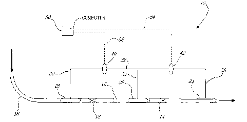
Description of the apparatus
An apparatus (10) according to a possible and preferred embodiment of the
present
invention is described hereinafter and illustrated in FIGS. 1 to 4. This
apparatus (10)
constitutes an example of a device to achieve the method. However, the method
may
also be put into practice using a different apparatus.
The apparatus (10) comprises a first static mixer (12) and a second static
mixer (14).
Both are mounted in series and all the fluid coming from a main supply pipe
(16) is
passed therein. The fluid immediately returns into the main pipe (16)
afterwards. The
outlet of the first static mixer (12) is connected to the inlet of the second
static mixer
(14) by means of an intermediary pipe (18), which can be a section of the main
pipe
(16) itself. As aforesaid, one could also deviate only a portion of the fluid
through the
apparatus (10) from the main pipe (16) or simply draw fluid from a tank (not
shown)
for analysis. .
The static mixers (12,14) are said to be non-identical because they should not
create
the same pressure drops in the fluid. Identical values of the pressure drops
will not
give good results. The highest pressure drop can be created in the first (12)
or the
second static mixer (14).
Many different models of static mixers are found on the market. The shape, the
flow
characteristics and the internal construction differ from one model to
another. A
number of factors have to be considered, such as the required extent of the
mix, the
pressure drop in the mixer, the diameter, the length, the shear rate, the
stagnation
time and the heat transfer. Most static mixers can be classified in either one
of two
categories. The first category includes the ones in which the mixing occurs by
rotation
. in a tube. These static mixers are relatively long and the pressure drop
therein is low.
The second class comprises the static mixers in which the mixing occurs by
stretching the fluid. These mixers are short and the pressure drop therein is
high.
CA 02365621 2001-09-27
WO 01/55696 PCT/CA01/00091
14
The apparatus (10) is preferably provided with static mixers of the first
category. An
example of a first static mixer is a Low Pressure Drop (LPD) mixer
manufactured by
ROSS T"" and schematically illustrated in FIG. 4. Assuming that the
illustrated static
mixer is the first static mixer (12), the static mixer (12) comprises a main
vessel (26)
and sets of two semi-elliptical baffles (28) intersecting each other with an
angle,
typically having value of 45° or 60° with reference to the flow
therein. Other models
of static mixers may be used.
There are many considerations to be taken into account when designing a
rheological
apparatus. For instance, the apparatus should not have region where the fluid
becomes stagnant or where solids may accumulate. Then, the flow has to be
laminar,
i.e. substantially non-turbulent, and with the minimum of perturbations since
they
decrease the precision of the apparatus and method. As aforesaid, the diameter
of
the main pipe (16), the static mixers (12,14) and the intermediary.pipe (18)
should be
the same. Yet, the section of the main pipe (16) should be long enough between
a
supply pump, if any, and the inlet of the first static mixer (12). The same
comment
applies to the outlet of the first static mixer (12) and the inlet of the
second static
mixer (14). However, the pipes should not be too long for preventing
sedimentation
to occur. Other arrangements (not shown) may be used to lower the
perturbations in
the flow, if necessary. Sufficient time should also be given for the flow to
stabilize
whenever the flow rate changes.
The. pressure drops through each static mixer (12, 14) are expressed as
pressure
differentials using appropriate sensors or any other suitable means.
Differential
pressure sensors are preferred over direct pressure measurements and
subsequent
subtraction of the measured values since typically, the pressure loss can be
as low
as 100 Pa with a line pressure between 100 and 300 kPa. FIGS. 2 and 3 show an
example of an arrangement used to achieve this goal. In this arrangement,
three
highly sensitive measuring cells are used, namely a first cell (20), a second
cell (22)
and a third cell (24). The first cell (20) is mounted on the apparatus (10)
upstream the
CA 02365621 2001-09-27
WO 01/55696 PCT/CA01/00091
inlet of the first static mixer (12), the second cell (22) is mounted on the
intermediary
pipe (18), near the inlet of the second static mixer (14) and the third cell
(24) is
mounted downstream the outlet of the second static mixer (14). These cells
(20, 22,
24) are connected in pairs by means of a circuit of rigid tubes (30, 32, 34,
36) leading
5 to corresponding differential pressure transducers (40, 42). The first cell
(20) is
connected to a first side of the first differential pressure transducer (40)
by means of
the first tube (30). The second cell (22) is connected to a second side of the
first
differential pressure transducer (40) by means of the second (32) and the
third tube
(34). The second cell (22) is connected to a first side of the second
differential
10 pressure transducer (42) by means of the second (32) and the third tube
(34). The
third cell (24) is connected to a second side of the second differential
pressure
transducer (42).
The tubes (30, 32, 34, 36) are filled with a substantially incompressible
liquid, such
15 as water or ethylene glycol. Each cell (20, 22, 24) comprises a deformable
membrane
(25) made of material that is able to correctly transmit the pressure to the
incompressible liquid and resist the abrasion of the fluid. Natural or
synthetic rubber
are examples of materials for the membrane (25). A purge opening (60) is
provided
to drain any air out of the tubes (30, 32, 34, 36). Air is also drained out
through a
small opening (62) located against the internal membrane of a transducer, such
as
the first transducer (40). The tubes (30, 32, 34, 36) are filled through a
valve (64).
The pressure drop of the fluid through the first static mixer (12) is measured
by the
first differential pressure transducer (40) and the pressure drop of the fluid
through
the second static mixer (14) is measured by the second differential pressure
transducer (42). Each transducer (40, 42) comprises an output terminal by
which a
corresponding differential pressure signal DP, or ~PZ is sent. The terminals
are
connected to a computer (50) by electrical wires (52, 54) or any other
suitable
arrangements. The computer (50) preferably perform all calculations in
corresponding
subroutines including the formulas described hereinabove.
CA 02365621 2001-09-27
WO 01/55696 PCT/CA01/00091
16
The present invention may be used to measure the rheological properties of
fluids in
a wide range of applications, such as paper manufacturing or coating, cosmetic
or
food preparation and in polymer synthesis.
The present invention is not limited to the described embodiment and
encompasses
any alternative embodiments within the limits defined by the claims.