Language selection

Search

Patent 2365682 Summary

Third-party information liability

Some of the information on this Web page has been provided by external sources. The Government of Canada is not responsible for the accuracy, reliability or currency of the information supplied by external sources. Users wishing to rely upon this information should consult directly with the source of the information. Content provided by external sources is not subject to official languages, privacy and accessibility requirements.

Claims and Abstract availability

Any discrepancies in the text and image of the Claims and Abstract are due to differing posting times. Text of the Claims and Abstract are posted:

  • At the time the application is open to public inspection;
  • At the time of issue of the patent (grant).
(12) Patent Application: (11) CA 2365682
(54) English Title: A SMALL BUILDING STRUCTURE FOR CONTAINING AND SHELTERING EQUIPMENT AND, PREFERABLY A SAFETY SHELTERING BOOTH FOR MOUNTING AND/OR CONNECTING AND/OR HOUSING AND SHELTERING EQUIPMENT,FOR ENERGY COMPANIES, TELECOMMUNICATION COMPANIES AND PUBLIC SERVICES IN GENERAL
(54) French Title: PETITE STRUCTURE DE BATIMENT SERVANT A CONTENIR ET A ABRITER DU MATERIEL, ET SERVANT DE PREFERENCE DE CABINE SECURITAIRE POUR INSTALLER ET/OU RACCORDER ET/OU CONTENIR ET ABRITER DUMATERIEL POUR DES SOCIETES D'ENERGIE, DES SOCIETES DE TELECOMMUNICATIONS ET DES SERVICES PUBLICS EN GENERAL
Status: Deemed Abandoned and Beyond the Period of Reinstatement - Pending Response to Notice of Disregarded Communication
Bibliographic Data
(51) International Patent Classification (IPC):
  • E04H 05/02 (2006.01)
(72) Inventors :
  • BOULLHESEN, PEDRO ARMANDO (Argentina)
  • MARTORELLO, JUAN CARLOS (Argentina)
  • CARLE, RUBEN EDGARDO (Argentina)
  • TORRES, CARLOS EDUARDO (Argentina)
(73) Owners :
  • PEDRO ARMANDO BOULLHESEN
  • JUAN CARLOS MARTORELLO
  • RUBEN EDGARDO CARLE
  • CARLOS EDUARDO TORRES
(71) Applicants :
  • PEDRO ARMANDO BOULLHESEN (Argentina)
  • JUAN CARLOS MARTORELLO (Argentina)
  • RUBEN EDGARDO CARLE (Argentina)
  • CARLOS EDUARDO TORRES (Argentina)
(74) Agent: DENNISON ASSOCIATES
(74) Associate agent:
(45) Issued:
(22) Filed Date: 2001-12-20
(41) Open to Public Inspection: 2002-06-22
Examination requested: 2004-01-29
Availability of licence: N/A
Dedicated to the Public: N/A
(25) Language of filing: English

Patent Cooperation Treaty (PCT): No

(30) Application Priority Data:
Application No. Country/Territory Date
M 00 01 06906 (Argentina) 2000-12-22

Abstracts

English Abstract


14
A shelter booth for housing and sheltering desired
equipment, the booth comprising an interior for receiving
the equipment, the interior being defined by a floor, a
roof, two end walls and two sides, with the sides defining
corresponding openings for providing access to the
interior, the openings including a plurality of bars and
door means removably mounted in the opening.


Claims

Note: Claims are shown in the official language in which they were submitted.

9
WE CLAIM:
1. A safety shelter booth for housing and
installation of equipment, the booth comprising:
a f loon
a roof,
two end walls,
two sides, and
an interior for mounting said equipment, the
interior being defined by said floor, roof, walls and
sides,
wherein at least one of the sides comprises:
an opening defining access to said interior of the
booth,
a plurality of bars in the interior of the booth
and adjacent the opening, the bars defining access to said
interior,
door means removably mounted in the opening.
2. The safety shelter booth of claim 1, wherein the
door means being removed from the opening for providing
access to the booth interior and being mounted and locked
in the opening for closing the booth, thus preventing any
access to the booth.

10
3. The safety shelter booth of claim 2, wherein the
opening is provided with mounting means and locking for
mounting the door means and locking the same in the
opening.
4. The safety shelter booth of claim 1, wherein the
bars extends through the entire opening and are spaced
apart permitting the passing of the hands and arms of any
personnel therethrough, with access to the equipment.
5. The safety shelter booth of claim 4, wherein
said bars are removably mounted in the booth.
6. The safety shelter booth of claim 1, wherein
said door means comprises door panels removably mounted in
the opening.
7. The safety shelter booth of claim 6, wherein the
mounting means of the opening comprises a plurality flanges
transversely extending from a side of the opening and
towards the opening for retaining the door panels, and the
locking means comprises at least one lock at a side of the
opening opposite the flanges.

11
8. The safety shelter booth of claim 7, wherein the
flange is one wing of a U-shaped bar, a corresponding edge
of a door panel being received within the U shape.
9. The safety shelter booth of claim 6, wherein the
door panels include handle means for handling the panels
during removal and mounting thereof.
10. The safety shelter booth of claim 1, wherein
the opening, the bars and the door means are provided at
both sides of the booth.
11. The safety shelter booth of claim 1, wherein
the roof extends out of at least one of the sides of the
booth forming an eaves over the opening.
12. The safety shelter booth of claim 11, wherein
the roof extends forming eaves at both sides of the booth.
13. The safety shelter booth of claim 1, wherein at
least one of the end walls includes air conditioning means.
14. The modular shelter booth of claim 1, wherein
the booth is transportable in an assembled condition.

12
15. The modular shelter booth of claim 1, wherein
the booth is transportable in a disassembled condition and
is assembled in situ.
16. A safety shelter booth for housing and
sheltering equipment comprising instruments, apparatii,
devices, used for telephone services, energy distribution,
and general public services, the booth being transportable
and comprising:
a floor,
a roof,
two end walls,
two sides, and
an interior for mounting said equipment, the
interior being defined by said floor, roof, walls and
sides,
wherein at least one of the sides comprises:
an opening defining access to said interior of the
booth,
a plurality of bars in the interior of the booth
and adjacent the opening, the bars defining access for
operating and maintaining the equipment but a barrier for
preventing the equipment from being removed from the booth,
door means removably mounted in the opening.

13
17. The safety shelter booth of claim 16, wherein
the opening is provided with mounting means and locking
means for mounting the door means and locking the same in
the opening
18. The safety shelter booth of claim 17, wherein
the mounting means of the opening comprises a plurality
flanges transversely extending from a side of the opening
and towards the opening for retaining the door panels, and
the locking means comprises at least one lock at a side of
the opening opposite the flanges, said door means
comprising door panels removably mounted in the opening
with the flange being one wing of a U-shaped bar and a
corresponding edge of a door panel being received within
the U shape.
19. The safety shelter booth of claim 16, wherein
an eaves is provided on the top of each opening.
20. The safety shelter booth of claim 16, wherein
the opening, the bars and the door means are provided at
both sides of the booth.

Description

Note: Descriptions are shown in the official language in which they were submitted.


CA 02365682 2001-12-20
A SMALL BUILDING STRUCTURE FOR CONTAINING AND SHELTERING
EQUIPMENT AND, PREFERABLY A SAFETY SHELTERING BOOTH FOR MOUNTING
AND/OR CONNECTING AND/OR HOUSING AND SHELTERING EQUIPMENT, FOR
ENERGY COMPANIES, TELECOMMUNICATION COMPANIES AND PUBLIC
SERVICES IN GENERAL
BACKGROUND OF THE INVENTION
1. Field of th~ Invention.
The present invention relates to a small building
structure for containing and sheltering equipment and,
preferably refers to a safety sheltering booth for mounting
and/or connecting and/or housing and sheltering equipment,
for energy companies, telecommunication companies and
public services in general, the booth being transported in
an assembled status or disassembled status to the desired
location, generally far away towns, in the country, the
booth being prepared to operate outdoor or indoor and it
provides sheltering not only against outdoor conditions but
also against any vandalism or delinquent actions.
To the purpose of the present specification the
term "equipment" is intended far referring to any kind of
products, apparatii, devices, instruments, machines,
preferably employed in general public services such as
telephone services, electricity supplying services,
cellular telephone services, antennas for telephone
services, broadcasting equipment, gas distribution
equipment, etc.

CA 02365682 2001-12-20
2
2. Description of the Prior Art.
With the increasing decentralization of huge towns
and the extension of existent public services and new
services the need arises for providing new towns, sometimes
far away from the main towns, with such public services but
also for providing far away already existent towns with
such new services such as electricity supplying, telephone
services, cellular telephony, gas distribution, etc., that
require of the installation of several equipment, such as
control apparatii, regulating devices, booster and/or
repeater antennae, which equipment is generally required in
the country, sometimes temporarily, wherein there are few
possibilities of building a large and complex structure for
the mounting and installation of such equipment.
Therefore, it would be very convenient and economic
to have a kind of easy transportable, safety and sheltering
small structure for permitting the installation of the
required equipment either in the assembling plant or in
situ, and installing the structure in the desired location
at a low cost.
SUI~iARY OF THE INVENTION
It is therefore one object of the present invention
to provide a sheltering booth for housing and sheltering
desired equipment, the booth comprising an interior for

CA 02365682 2001-12-20
3
receiving the equipment, the interior being defined by a
floor, a roof, two end walls and two sides, with one or
both sides defining corresponding openings for providing
access to the interior, the openings including a plurality
of bars and door means remavably mounted in the opening.
It is still another object of the present invention
to provide a safety shelter booth for housing and
installation of equipment, the booth comprising a floor, a
roof, two end walls, two sides, and an interior for
mounting said equipment, the interior being defined by said
floor, roof, walls and sides, wherein one of the sides or
each side comprises an opening defining access to said
interior of the booth, a plurality of bars in the interior
of the booth and adjacent the opening, the bars defining
access to said interior, and door means removably mounted
in the opening.
It is a further object of the present invention to
provide a safety shelter booth for housing and sheltering
equipment comprising instruments, apparatii, devices, used
for telephone services, energy distribution, and general
public services, the booth being transportable and
comprising a floor, a roof, two end walls, two sides, and
an interior for mounting said equipment, the interior being
defined by said floor, roof, walls and sides, wherein one
or both sides comprises an opening defining access to said
interior of the booth, a plurality of bars in the interior

CA 02365682 2001-12-20
4
of the booth and adjacent the opening, the bars defining
access for operating and maintaining the equipment but a
barrier for preventing the equipment from being removed
from the booth, and door means removably mounted in the
opening.
The above and other objects, features and
advantages of this invention will be better understood when
taken in connection with the accompanying drawings and
description.
BRIEF DESCRIPTION OF THE DRAWIN~3S
The present invention is illustrated by way of
example in the following drawings wherein:
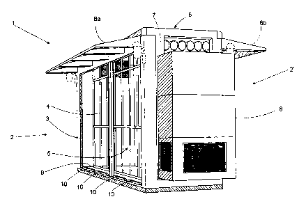
FIG. 1 shows a perspective elevational view of a
booth according to the invention, with the door panels
removed from a side of the booth;
FIG. 2 shows a side elevational perspective view of
the inventive booth with the door panels mounted in the
booth. for clo~3ing the same; and
FIG. 3 shows a top plan cross-sectional view of the
booth of the invention.
DESCRIPTION OF THE PREFERRED EMBODIMElaTS
Now referring in detail to the drawings it may be
seen from FIGS. 1-3 a shelter booth according to the
invention and indicated by general reference 1. Booth 1 is

CA 02365682 2001-12-20
comprised of a small and strong structure which in turn is
made of preferably light material such as light metal
profiles and bars and plastic materials.
Booth 1 is a safety shelter booth preferably for
housing and sheltering equipment comprising equipment such
as instruments, apparatii, devices and the like, used for
telephone services, energy distribution, and general public
services, with the booth being transportable and capable of
being assembled from a plurality of modular parts, the
assembling being carried out either in a manufacturing
plant or in situ, namely in the location wherein the booth
is to be installed. Booth 1 comprises a pair of sides 2 and
2', wherein one or, preferably both, sides 2, 2', are
provided with an opening defined by a periphery 3 extending
in all the corresponding side 2, 2'. While FIG. 1 shows
only one open side 2, both sides 2, 2' including the
opening defined by reference 3 in FIG. 1 are shown in the
cross-section of FIG. 3. In any event, opening defined by 3
may be provided only in one side or in both sides of the
booth.
An interior 5 is defined by end walls 7, sides 2,
2', a floor 9 and a roof 6, the interior being provided
with the necessary means for mounting equipment 14 (FIG. 3)
and permitting the installation and connection thereof. The
interior of booth 1 is also provided with a plurality of
bars 4 adjacent the opening of the sides of the booth, the

CA 02365682 2001-12-20
6
bars forming a barrier for preventing any person from
removing any part of equipment 14 but the bars are spaced
apart in an extent enough for permitting the servicing of
the equipment by leaving spaces enough for passing the
hands and arms of the service personnel without the need of
entering the interior 5 of booth 1. Bars 4 are preferably
removably mounted in the interior of the booth by any
mounting means and locked in place also by any conventional
locking means.
The roof of the booth may extend at one side or at
both sides of the booth forming eaves 6a, 6b def fined over
the opening at a corresponding side 2, 2'. Eaves 6a, 6b,
however, may be independent of the roof and independent
structures may be fixed at corresponding sides 2, 2', for
construing eaves 6a, 6b. Eaves 6a, 6b provides convenient
shelter for the servicing personnel when manipulating the
equipment, with the personnel and the equipment being
protected from the weather conditions.
End walls~7 are useful for the mounting of any
accessory necessary for the operation of the equipment in _
the booth, these accessories being one or two air
conditioning apparatus 8, for example. Connection panels,
venting means etc., may also be provided in walls 7. In
phantom lines also a pair of lights is shown in the corners
of walls 7 and sides 2, 2'.

CA 02365682 2001-12-20
7
Open sides 2, 2' are provided with door means
comprising door panels 11 which are removably mounted in
the corresponding opening and are capable of being removed
from the opening for providing access to the booth interior
and capable of being mounted and locked in the opening for
closing the booth, thus preventing any access to the booth.
Panels 11 are removably mounted in the openings by means of
mounting means comprising a plurality flanges transversely
extending from a side, preferably a bottom side as
illustrated in FIGS. 1 and 2, of the opening and towards
the opening for retaining the door panels as shown in FIG.
2. The retaining flanges corresponding to the wings of
corresponding U-shaped bars 10, with a corresponding edge
of a door panel being received within the U shape.
Each door panel 11 may be provided with handle
means for handling the panels during removal and mounting
thereof, the handle means preferably comprising one handle
13, or preferably two handles 13, in each door panel 11.
When each door panel ~1 is mounted with a bottom edge
thereof within U-shaped bar 10, an upper edge of the door
panel is locked in position by means of locking means,
preferably at least one lock 12 arranged at a side of the
opening opposite mounting profiled bars 10.
While a plurality of door panels 11 that are
mounted within a plurality of U-shape bars have been
illustrated in the floor 9, it will be obvious for any

CA 02365682 2001-12-20
g
person skilled in the art that only one door panel may be
provided for closing opening 3. In like manner, U bars 10
may be provided at any side of the open side 2, 2', in
which event lock 12 will be preferably provided at an
opposite side of the opening.
The walls and sides of the booth may be
manufactured of any appropriate material that may be
necessary for protecting and sheltering equipment 14 which
equipment is generally a very sensitive equipment
comprising electronics and other instruments that must be
isolated enough from any weather condition, vandalism,
cattle and general animals action, etc.
While preferred embodiments of the present
invention have been illustrated and described, it will be
obvious to those skilled in the art that various changes
and modifications may be made therein without departing
from the scope of the invention as defined in the appended
claims. ' '

Representative Drawing
A single figure which represents the drawing illustrating the invention.
Administrative Status

2024-08-01:As part of the Next Generation Patents (NGP) transition, the Canadian Patents Database (CPD) now contains a more detailed Event History, which replicates the Event Log of our new back-office solution.

Please note that "Inactive:" events refers to events no longer in use in our new back-office solution.

For a clearer understanding of the status of the application/patent presented on this page, the site Disclaimer , as well as the definitions for Patent , Event History , Maintenance Fee  and Payment History  should be consulted.

Event History

Description Date
Application Not Reinstated by Deadline 2008-05-08
Inactive: Dead - No reply to s.29 Rules requisition 2008-05-08
Deemed Abandoned - Failure to Respond to Maintenance Fee Notice 2007-12-20
Inactive: Abandoned - No reply to s.30(2) Rules requisition 2007-05-08
Inactive: Abandoned - No reply to s.29 Rules requisition 2007-05-08
Inactive: S.29 Rules - Examiner requisition 2006-11-08
Inactive: S.30(2) Rules - Examiner requisition 2006-11-08
Letter Sent 2004-02-23
Letter Sent 2004-02-13
Request for Examination Requirements Determined Compliant 2004-01-29
Request for Examination Received 2004-01-29
All Requirements for Examination Determined Compliant 2004-01-29
Reinstatement Requirements Deemed Compliant for All Abandonment Reasons 2004-01-29
Deemed Abandoned - Failure to Respond to Maintenance Fee Notice 2003-12-22
Application Published (Open to Public Inspection) 2002-06-22
Inactive: Cover page published 2002-06-21
Inactive: First IPC assigned 2002-02-21
Application Received - Regular National 2002-01-23
Inactive: Filing certificate - No RFE (English) 2002-01-23

Abandonment History

Abandonment Date Reason Reinstatement Date
2007-12-20
2003-12-22

Maintenance Fee

The last payment was received on 2006-10-31

Note : If the full payment has not been received on or before the date indicated, a further fee may be required which may be one of the following

  • the reinstatement fee;
  • the late payment fee; or
  • additional fee to reverse deemed expiry.

Patent fees are adjusted on the 1st of January every year. The amounts above are the current amounts if received by December 31 of the current year.
Please refer to the CIPO Patent Fees web page to see all current fee amounts.

Fee History

Fee Type Anniversary Year Due Date Paid Date
Application fee - standard 2001-12-20
Request for examination - standard 2004-01-29
Reinstatement 2004-01-29
MF (application, 2nd anniv.) - standard 02 2003-12-22 2004-01-29
MF (application, 3rd anniv.) - standard 03 2004-12-20 2004-11-17
MF (application, 4th anniv.) - standard 04 2005-12-20 2005-12-19
MF (application, 5th anniv.) - standard 05 2006-12-20 2006-10-31
Owners on Record

Note: Records showing the ownership history in alphabetical order.

Current Owners on Record
PEDRO ARMANDO BOULLHESEN
JUAN CARLOS MARTORELLO
RUBEN EDGARDO CARLE
CARLOS EDUARDO TORRES
Past Owners on Record
None
Past Owners that do not appear in the "Owners on Record" listing will appear in other documentation within the application.
Documents

To view selected files, please enter reCAPTCHA code :


To view images, click a link in the Document Description column. To download the documents, select one or more checkboxes in the first column and then click the "Download Selected in PDF format (Zip Archive)" or the "Download Selected as Single PDF" button.

List of published and non-published patent-specific documents on the CPD .

If you have any difficulty accessing content, you can call the Client Service Centre at 1-866-997-1936 or send them an e-mail at CIPO Client Service Centre.


Document
Description 
Date
(yyyy-mm-dd) 
Number of pages   Size of Image (KB) 
Representative drawing 2002-02-24 1 23
Abstract 2001-12-19 1 14
Description 2001-12-19 8 311
Claims 2001-12-19 5 135
Drawings 2001-12-19 3 81
Filing Certificate (English) 2002-01-22 1 165
Reminder of maintenance fee due 2003-08-20 1 106
Acknowledgement of Request for Examination 2004-02-12 1 174
Courtesy - Abandonment Letter (Maintenance Fee) 2004-02-15 1 177
Notice of Reinstatement 2004-02-22 1 168
Courtesy - Abandonment Letter (R30(2)) 2007-07-16 1 166
Courtesy - Abandonment Letter (R29) 2007-07-16 1 166
Courtesy - Abandonment Letter (Maintenance Fee) 2008-02-13 1 176
Fees 2004-01-28 1 34