Language selection

Search

Patent 2365788 Summary

Third-party information liability

Some of the information on this Web page has been provided by external sources. The Government of Canada is not responsible for the accuracy, reliability or currency of the information supplied by external sources. Users wishing to rely upon this information should consult directly with the source of the information. Content provided by external sources is not subject to official languages, privacy and accessibility requirements.

Claims and Abstract availability

Any discrepancies in the text and image of the Claims and Abstract are due to differing posting times. Text of the Claims and Abstract are posted:

  • At the time the application is open to public inspection;
  • At the time of issue of the patent (grant).
(12) Patent Application: (11) CA 2365788
(54) English Title: POWER ADAPTER WITH CABLE STORAGE DEVICE
(54) French Title: ADAPTATEUR DE PUISSANCE AVEC DISPOSITIF DE RANGEMENT DE CABLE
Status: Deemed Abandoned and Beyond the Period of Reinstatement - Pending Response to Notice of Disregarded Communication
Bibliographic Data
(51) International Patent Classification (IPC):
  • H02G 11/00 (2006.01)
  • B65H 75/14 (2006.01)
  • B65H 75/38 (2006.01)
  • H01R 13/72 (2006.01)
  • H01R 31/06 (2006.01)
  • H02G 11/02 (2006.01)
(72) Inventors :
  • CHUNG, YU-LIN (Taiwan, Province of China)
(73) Owners :
  • YU-LIN CHUNG
(71) Applicants :
  • YU-LIN CHUNG (Taiwan, Province of China)
(74) Agent:
(74) Associate agent:
(45) Issued:
(22) Filed Date: 2001-12-20
(41) Open to Public Inspection: 2003-06-20
Availability of licence: N/A
Dedicated to the Public: N/A
(25) Language of filing: English

Patent Cooperation Treaty (PCT): No

(30) Application Priority Data: None

Abstracts

English Abstract


A power adapter includes a body having an upper portion on which a
first plug is formed for connection with a wall outlet and a lower portion
defining a recess with an axle formed therein for rotatably supporting a reel.
A lid is attached to the body for covering the recess. The reel includes a
first disk and a second disk mounted together with a coil spring received
therebetween. The coil spring biases the reel in a winding direction for
winding a cable thereon. The cable has a first end extending through a
central bore of the axle and electrically connected to the first plug and a
second end extending beyond the body through an opening defined in the
body. A second plug is formed on the second end for connection with an
electrical device. The cable may be extended out of the body by being
pulled in an unwinding direction against the coil spring. A locking slide is
mounted on the body and movable between a closed position and an open
position. The locking slide forms a pawl engageable with the cable when
the slide is moved to the closed position thereby securing the cable in
position.


Claims

Note: Claims are shown in the official language in which they were submitted.

WHAT IS CLAIMED IS
1. ~A power adapter comprising a body on which a first plug is formed,
the body defining an interior space with a reel rotatably supported
therein, a cable being wound around the reel and having a first end
electrically connected to the first plug and a second end extending
beyond the body, a second plug being formed on the second end of the
cable, the reel being rotatable in a first direction to unwind the cable
therefrom thereby allowing the cable to extend outside the body and
rotatable in an opposite second direction to wind the cable and thus
retract the cable into the body, biasing means being arranged between
the reel and the body for biasing the reel in the second direction.
2. ~The power adapter as claimed in Claim 1, wherein an opening is
defined in the body for the extension of the cable, lacking means
being formed on the body adjacent the opening for engaging and thus
fixing the cable in position when the cable is released out of the body.
3. ~The power adapter as claimed in Claim 2, wherein the locking means
comprises a slide movable between a closed position and an open
position, the slide having an end with a pawl formed thereon for
engaging the cable when the slide is moved to the closed position.
4. ~The power adapter as claimed in Claim 1, wherein the biasing means
comprises a coil spring.
6

Description

Note: Descriptions are shown in the official language in which they were submitted.


CA 02365788 2001-12-20
PUWER ADAPTER WITH CABLE STURAGE DEVICE
The present invention generally relates to a power adapter for
connection between a wall outlet and an electrical device, such as a mobile
phone and a notebook computer. More particularly, the present invention
relates to a power adapter having a cable storage device for storage of a
cable thereof.
A portable electrical device is often powered by an internal power
source, such as a battery set. The internal power source which is usually
a rechargeable battery set requires recharging. Thus, a power adapter is
used to connect the portable electrical device to an electrical main, such as
a wall outlet, for recharging the internal power source or directly powering
the portable electrical device.
. Figure 4 of the attached drawings shows a conventional power
adapter. The power adapter comprises a body 100 on which an input plug
200 is formed for connection with a wall outlet (not shown). A cable or
cord 300 having a first end electrically connected to the input plug 200
extends from the body 100 with a remote second end forms an output plug
400 for connection with a portable electrical device. A disadvantage of
the conventional power adapter is that the cable 300 is completely located
outside the body 100. This may cause problem to a user of the portable
electrical device. The cable is often tied together by a rope or a rubber
band.. It is inconvenient to the user.
Thus, it is desired to have a power adapter having a cable storage
device for overcoming the above problems.

CA 02365788 2001-12-20
Accordingly, an object of the present invention is to provide a power
adapter having a cable storage device for advantageously storing an
extension cable therein, the cable being readily extended for connection
with an electrical device.
Another object of the present invention is to provide a power adapter
with an extension cable stored inside a body thereof, the cable being
arbitrarily extendible for ready use.
In accordance with the present invention, there is provided a power
adapter comprising a body having an upper portion on which a first plug is
formed for connection with a wall outlet and a lower portion defining a
recess with an axle formed therein for rotatably supporting a reel. A lid is
attached to the body for covering the recess. The reel comprises a first
disk and a second disk mounted together with a coil spring received
therebetween. The coil spring biases the reel in a winding direction for
winding a cable thereon. The cable has a first end extending through a
central bore of the aYie and electrically connected to the first plug and a
second end extending beyond the body through an opening defined in the
body. A second plug is formed on the second end far connection with an
electrical device. The cable may be extended out of the body by being
pulled in an unwinding direction against the coil spring. A locking slide is
mounted on the body and movable between a closed position and an open
position. The locking slide forms a pawl engageable with the cable when
the slide is moved to the closed position thereby securing the cable in
position.
2

CA 02365788 2001-12-20
The present invention will be apparent to those skilled in the art by
reading the following description of preferred embodiments thereof, with
reference to the accompanying drawings, in which:
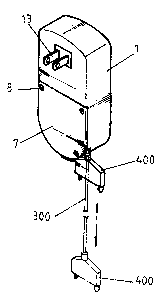
Figure I is a perspective view of a power adapter constructed in
accordance with the present invention;
Figure 2 is an exploded view of the power adapter of the present
invention;
Figure 3 is a front view of the power adapter with a lid removed to
. show inside details; and
Figure 4 is a perspective view of a conventional power adapter.
With reference to the drawings and in particular to Figures l and 2,
wherein a power adapter constructed in accordance with the present
invention is shown, the power adapter comprises a body I having an upper
portion on which a first plug 13 is formed for connection with for example
a wall outlet (not shown) and a lower portion defining an interior space I I
covered by a removable lid 7. The lid 7 is attached to the body 1 by any
know means, such as bolts 8 engageable with inner-threaded holes 14
formed in the interior space 11.
A reel assembly is rotatably supported in the interior space 11 of the
body 1 with a cable 300 wound thereon. The reel assembly comprises a
first disk S and a second disk 3 coaxially mounted to each other for
defining a space therebetween to receive a coil spring 4 for biasing the reel
assembly in a winding direction. An axle 2 is mounted inside the interior
3

CA 02365788 2001-12-20
space 1 I and extends through central bores defined in the disks 5 and 3 for
rotatably supporting the reel assembly.
An inner end of the cable 300 extends through a central bore (not
labeled) of the axle 2 for being electrically connected to the first plug I3.
A portion of the cable 300 is wound between the disks 5 and 3 with an
outer end of the cable 300 extending beyond the body 1 whereby when a
user pulls the outer end of the cable 300, the reel assembly rotates in an
unwinding direction against the coil spring 4 for extending the cable 300 as
shown by phantom lines of Figure 1. A second plug 400 is mounted on
IO the outer end of the cable 300 for connection to an electrical device
whereby electrical power is supplied from the wall outlet through the cable
300 to the electrical device.
When the cable 300 is released, the coil spring 4 which exerts a
biasing force on the reel assembly in the winding direction forces the reel
I5 assembly to rotate in the winding direction thereby retracting the cable
300
into the interior space I I of the body 1.
Also referring to Figure 3, a race 12 is defined in the body 1 for
receiving a slide 6 therein. The slide 6 is movable in the race 12 between
a closed position and an open position. A projection 61 is formed on the
20 slide 6 for facilitating manually moving the slide 6 in the race 12. An
opening (not labeled) is defined in the body 1 through which the cable 300
extends. The opening is located next the race I2 whereby when the slide
6 is moved to the closed position, a pawl 62 formed on the slide 6 engages
and thus fixes the cable 300 and when the slide 6 is moved to the open
25 position, the cable 300 is released.
To this point, it is understood that the present invention allows a user
to arbitrarily extend the cable 300 by pulling the cable 300 against the coil
spring 4 and to fix the cable 300 in position by using the slide 6.

CA 02365788 2001-12-20
Although the present invention has been descn'bed with respect to the
preferred embodiments, it is contemplated that a variety of modifications,
variations and substitutions may be done without dep~xring from the scope
of the present inventioxt that is intended to be defined by the appended
claims.
5

Representative Drawing
A single figure which represents the drawing illustrating the invention.
Administrative Status

2024-08-01:As part of the Next Generation Patents (NGP) transition, the Canadian Patents Database (CPD) now contains a more detailed Event History, which replicates the Event Log of our new back-office solution.

Please note that "Inactive:" events refers to events no longer in use in our new back-office solution.

For a clearer understanding of the status of the application/patent presented on this page, the site Disclaimer , as well as the definitions for Patent , Event History , Maintenance Fee  and Payment History  should be consulted.

Event History

Description Date
Inactive: IPC from MCD 2006-03-12
Application Not Reinstated by Deadline 2005-11-30
Inactive: Dead - No reply to Office letter 2005-11-30
Inactive: Adhoc Request Documented 2005-09-22
Deemed Abandoned - Failure to Respond to Maintenance Fee Notice 2004-12-20
Inactive: Abandoned - No reply to Office letter 2004-11-30
Revocation of Agent Requirements Determined Compliant 2004-08-30
Inactive: Office letter 2004-08-30
Revocation of Agent Request 2004-08-11
Application Published (Open to Public Inspection) 2003-06-20
Inactive: Cover page published 2003-06-19
Inactive: IPC assigned 2002-03-05
Inactive: First IPC assigned 2002-03-05
Inactive: IPC removed 2002-03-05
Application Received - Regular National 2002-01-24
Inactive: Filing certificate - No RFE (English) 2002-01-24

Abandonment History

Abandonment Date Reason Reinstatement Date
2004-12-20

Maintenance Fee

The last payment was received on 2003-12-19

Note : If the full payment has not been received on or before the date indicated, a further fee may be required which may be one of the following

  • the reinstatement fee;
  • the late payment fee; or
  • additional fee to reverse deemed expiry.

Patent fees are adjusted on the 1st of January every year. The amounts above are the current amounts if received by December 31 of the current year.
Please refer to the CIPO Patent Fees web page to see all current fee amounts.

Fee History

Fee Type Anniversary Year Due Date Paid Date
Application fee - standard 2001-12-20
MF (application, 2nd anniv.) - standard 02 2003-12-22 2003-12-19
Owners on Record

Note: Records showing the ownership history in alphabetical order.

Current Owners on Record
YU-LIN CHUNG
Past Owners on Record
None
Past Owners that do not appear in the "Owners on Record" listing will appear in other documentation within the application.
Documents

To view selected files, please enter reCAPTCHA code :


To view images, click a link in the Document Description column. To download the documents, select one or more checkboxes in the first column and then click the "Download Selected in PDF format (Zip Archive)" or the "Download Selected as Single PDF" button.

List of published and non-published patent-specific documents on the CPD .

If you have any difficulty accessing content, you can call the Client Service Centre at 1-866-997-1936 or send them an e-mail at CIPO Client Service Centre.


Document
Description 
Date
(yyyy-mm-dd) 
Number of pages   Size of Image (KB) 
Representative drawing 2002-03-21 1 5
Description 2001-12-19 5 212
Abstract 2001-12-19 1 37
Claims 2001-12-19 1 43
Drawings 2001-12-19 4 50
Filing Certificate (English) 2002-01-23 1 164
Reminder of maintenance fee due 2003-08-20 1 106
Notice: Maintenance Fee Reminder 2004-09-20 1 123
Courtesy - Abandonment Letter (Maintenance Fee) 2005-02-13 1 175
Courtesy - Abandonment Letter (Office letter) 2004-12-20 1 166
Second Notice: Maintenance Fee Reminder 2005-06-20 1 116
Notice: Maintenance Fee Reminder 2005-09-20 1 119
Fees 2003-12-18 1 33
Correspondence 2004-08-10 1 24
Correspondence 2004-08-29 1 16
Correspondence 2004-08-29 1 24