Language selection

Search

Patent 2366220 Summary

Third-party information liability

Some of the information on this Web page has been provided by external sources. The Government of Canada is not responsible for the accuracy, reliability or currency of the information supplied by external sources. Users wishing to rely upon this information should consult directly with the source of the information. Content provided by external sources is not subject to official languages, privacy and accessibility requirements.

Claims and Abstract availability

Any discrepancies in the text and image of the Claims and Abstract are due to differing posting times. Text of the Claims and Abstract are posted:

  • At the time the application is open to public inspection;
  • At the time of issue of the patent (grant).
(12) Patent: (11) CA 2366220
(54) English Title: METHOD AND DEVICE FOR COLLECTING OIL MIXED WITH ICE BLOCKS
(54) French Title: PROCEDE ET DISPOSITIF DE RECUPERATION DE PETROLE MELANGE A DES BLOCS DE GLACE
Status: Expired and beyond the Period of Reversal
Bibliographic Data
(51) International Patent Classification (IPC):
  • B63B 35/32 (2006.01)
  • E02B 15/04 (2006.01)
(72) Inventors :
  • MYKKANEN, ERKKI (Finland)
(73) Owners :
  • SUOMEN YMPARISTOKESKUS
(71) Applicants :
  • SUOMEN YMPARISTOKESKUS (Finland)
(74) Agent: OYEN WIGGS GREEN & MUTALA LLP
(74) Associate agent:
(45) Issued: 2006-01-31
(86) PCT Filing Date: 2000-03-13
(87) Open to Public Inspection: 2000-09-14
Examination requested: 2002-03-08
Availability of licence: N/A
Dedicated to the Public: N/A
(25) Language of filing: English

Patent Cooperation Treaty (PCT): Yes
(86) PCT Filing Number: PCT/FI2000/000195
(87) International Publication Number: WO 2000053488
(85) National Entry: 2001-09-10

(30) Application Priority Data:
Application No. Country/Territory Date
990540 (Finland) 1999-03-11

Abstracts

English Abstract


The objective of the present invention is a method and a device for separating
oil from ice. In the method according to the invention,
ice is pressed under the water along an inclined surface formed by a bar
screen (3) or a grating. The oil is separated from the ice by
vibrating the inclined surface formed by the bar screen (3).


French Abstract

La présente invention concerne un procédé et un dispositif servant à séparer le pétrole de la glace. Selon le procédé de l'invention, la glace est poussée sous l'eau le long d'une surface inclinée formée par une grille à barreaux (3) ou un grillage. On sépare ensuite le pétrole de la glace en faisant vibrer la surface inclinée formée par la grille à barreaux (3).

Claims

Note: Claims are shown in the official language in which they were submitted.

-5-
Claims
1. A method for separating oil from a mixture of ice blocks and water, com-
prising forcing the ice blocks (1) under the water along the inclined surface
at least
partly formed by a bar screen or a grating (3) attached to a vessel, while the
vessel
moves forward, characterized in that the oil is separated from the ice blocks
(1) by
vibrating, back and forth against the ice blocks (1), the inclined surface
comprising
the bar screen or the grating (3).
2. A method according to Claim 1, characterized in that vibration is effected
essentially in the vertical direction.
3. A method according to Claim 1, characterized in that vibration is effected
obliquely forward or obliquely backward.
4. A method according to any one of Claims 1 to 3, characterized in that
vibration is caused by eccentric mass (6) or a crank mechanism.
5. A method according to any one of Claims 1 to 4, characterized in that the
oil
that has come loose as a consequence of vibration is collected through a
collecting
space (4) to an oil separation unit, where the water and the oil are
separated.
6. A device attached to a vessel for separating oil from a mixture of ice
blocks
and water, the device (2) comprising an inclined surface at least partly
formed by a
bar screen or a grating (3) for forcing the ice blocks (1) under the water
while the
vessel moves forward, characterized in that the device comprises a means for
vibrating the inclined surface comprising the bar screen or the grating (3)
back and
forth against the ice blocks (1) for separating the oil from the ice blocks
(1).
7. A device according to Claim 6, characterized in that the device (2) is
attached to the side or the bow of the vessel
8. A device according to Claim 6 or 7, characterized in that the device (2) is
attached to the vessel so that it can be detached.
9. A device according to Claim 6 or 7, characterized in that the device (2) is
fixedly attached to the vessel.

-6-
10. A device according to any one of Claims 6 to 9, characterized in that the
vessel is an icebreaker.

Description

Note: Descriptions are shown in the official language in which they were submitted.


CA 02366220 2001-09-10
WO 00/53st88 PCT/FI00/OOI95
1
Method and device for collecting oil mixed with ice blocks
The objective of the invention is a method and a device for collecting oil
mixed with
ice blocks.
As a consequence of ships striking a rock, colliding or equipment failure, oil
can get
into the water. Collecting oil from water is especially difficult when the
water is
partly or fully covered by ice. The situation is particularly difficult when
the oil is in
a broken ice field, such as a fairway. In that case, oil is not only on the
lower
surface of the ice, but also mixed with the ice blocks and trash ice and, to
some
extent, even on top of the ice. Collecting oil from ice blocks by using the
equipment
on the market has not been efficient enough. The state of the art recognizes a
low-
gradient plane that pushes ice blocks under the surface of the water; as a
result, part
of the oil comes off, and the dispersed oil can be recovered by using various
methods.
Patent publication FI 80746 describes an application on board a vessel to
collect oil
from among ice blocks. The application comprises a bow member with a low-
gradient, planar lower surface that is provided with intake openings for water
containing impurities. When the vessel moves forward, ice blocks are submerged
below the surface and are washed at the same time. According to the
publication,
intensive water jets can enhance washing. The bow is a part that is separate
from the
actual body of the vessel and it can be lifted and lowered to achieve optimal
driving
conditions.
Patent application FI 73029 describes a method for collecting oil from a water
level
covered with ice. In the method, if needed, ice is broken into small enough
pieces so
that they can be submerged below the water level by using the equipment
available.
Oil, that comes off the ice blocks by washing with water streams that are
generated
by submerging the ice blocks, is recovered.
Patent application US 4 039 454 describes a device for separating oil from
water
and floating ice blocks. This device also comprises an inclined plane that
forces the
ice blocks under water. The plane consists of a grating through which the oil
can
rise and be transferred to the collection equipment. Oil is removed from ice
blocks
when the ice blocks are submerged under the water.

CA 02366220 2001-09-10
WO 00/53488 PCT/FI00/00195
2
Patent publication FI 75014 describes an application on board a vessel for
collecting
oil from among ice blocks. The lower surface of the vessel bow is low-gradient
so
that, when the vessel moves forward, ice blocks are submerged under the water,
simultaneously being washed by the water. The lower surface of the inclined
plane
comprises bristles that sweep the upper surfaces of the ice blocks. The lower
surface
of the plane comprises water intake openings and the oil is separated from the
water
inside the vessel. The water that is pumped out is sprayed on the ice blocks
from
which the oil is to be removed.
In prior art solutions, the separation of oil from the ice blocks is solely
based on the
buoyant force of oil in relation to water, when ice blocks are forced under
the water
level. This separation method is not efficient and the majority of the oil
remains
attached to the ice blocks. By using the method and the equipment according to
the
invention, oil can be removed from ice blocks considerably more efficiently
than
before.
The objective of the invention is a method for separating oil from ice blocks,
comprising forcing the ice blocks under the water along an inclined surface
formed
by a bar screen or a grating attached to the vessel. The method is
characterized ~in
that oil is separated from ice blocks by vibrating the inclined surface formed
by the
bar screen. Vibrating is preferably effected in an essentially vertical
direction. The
pounding movement of the bar screen now drives the ice downward and the
buoyant
force of the water returns them to the bar screen. As a result of the impacts,
oil is
detached from the ice and it rises to the water level above the bar screen,
from
where it can be collected by using various methods.
Another objective of the invention is a device for the method described above.
The
device, comprising an inclined surface formed by a bar screen or a grating for
forcing ice blocks under water, is attached to the side or bow of the ship
and, when
the ship is propelled, a movement that forces the ice downwards is generated.
The
device is characterized in that oil is separated from the ice blocks by
vibrating the
inclined surface formed by the bar screen. Vibrating is preferably effected in
essentially the vertical direction.
In the following, the invention is described with reference to the appended
drawings
in which:
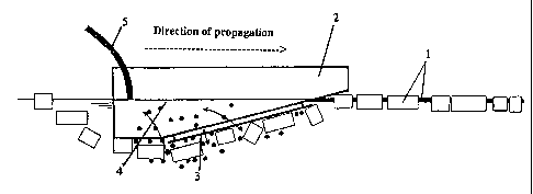
Fig. 1 shows the operating principle of the device according to the invention
to
separate oil from ice,

CA 02366220 2001-09-10
WO 00/53488 PCT/FI00/00195
3
Fig. 2 is a side view of a device according to the invention, and
Fig. 3 shows a view of a bar screen according to the invention as viewed from
below.
Device 2 according to the invention is either detachably or fixedly attached
to the
side or the bow of a vessel. Device 2 is preferably attached so that it can be
detached, so that the vessel can also be used for other purposes. Furthermore,
a
preferred location is on the side of the ship, as the screw can see device 2,
which
improves security and no separate personnel are needed for the operation of
device
2.
When the vessel moves forward, ice blocks l, among which and attached to which
there is oil, are forced under water along the inclined plane formed by bar
screen 3
or a grating. Bar screen 3 is preferably inclined in such a way that, as a
result of the
ship's movement, the ice blocks slide along the inclined plane and the plane
does
not push them in front of it. A preferred inclination is, e.g., about 13 to 15
degrees.
Bar screen 3 is preferably made of steel or other material that is suitable
for the
purpose.
Bar screen 3 is vibrated by a method known per se, for example, by eccentric
mass
or a crank mechanism. Bar screen 3 is moved in the vertical direction, pivoted
axle
7 limiting the movement of its other end. The pivoted axle can be located on
the
leading or the trailing edge of device 2. Device 2 can also be moved back and
forth
by using linear guides, or vibration can have a rotating trajectory. Vibration
is
preferably effected essentially in the vertical direction but can also be
carried out
obliquely forward or backward.
In one embodiment according to the invention, illustrated by Fig. 2, pivoted
axle 7
is located as far front as possible, so that there is a substantial amount of
movement
for bar screen 3 on the water level. A reciprocal movement is effected by push-
pull
rod 8 attached to the rear end of device 2, the rod being propelled by
eccentric mass
6 rotated by a suitable, power-generating device, such as electric or
hydraulic motor
9. The rotative velocity and the stroke of eccentric mass 6 can be adjusted.
By
adjusting the length of stroke, the amplitude of vibration can be changed and
by
adjusting the rotative velocity, the frequency of vibration can be changed.
The pounding movement of bar screen 3 drives ice blocks 1 downward and the
buoyant force of the water puts them back in contact with the bar screen. As a
consequence of the impacts, oil is detached from ice blocks 1 and rises to the

CA 02366220 2001-09-10
WO 00/53488 PCT/FI00/00195
4
surface of the water to collecting space 4 above bar screen 3, from where it
can be
transferred by using water flow S, for example, to an oil separation unit that
is
preferably located inside the ship, so that it is not exposed to the stress
caused by
ice or coldness. On the market, there are various methods that are suitable
for
S separation.
Bar screen 3 allows the water to freely drift above it, but holds the majority
of ice
blocks under it. Other grate-type plates can also be used, provided that they
do not
prevent the water from drifting.
Adjusting the direction of vibration so that it feeds ice under bar screen 3
can
enhance the drifting of ice blocks 1 under bar screen 3. Furthermore, the
drifting of
ice blocks 1 under bar screen 3 can be enhanced, for example, by locating a
paddle
wheel or other active ice-feeding device in the front end of device 2.
Bar screen 3 can also be located in device 2 so that the part formed by bar
screen 3
is horizontal so that the pitch angle is replaced by an S-upslope at the bow.
The method and the device according to the invention are especially viable on
a
fairway where there is passage broken for traffic or a passage caused by ship
traffic.
The device can also be attached to an icebreaker, so that the same vessel can
first
break the fast ice and after this or at the same time carry out oil separation
from the
ice by using the method according to the invention.
The description discloses some embodiments of the invention. However, the
invention is not limited to only relate to these special cases but the various
features
of the invention can be modified within the extent of the appended claims
without
leaving the scope of the invention.

Representative Drawing
A single figure which represents the drawing illustrating the invention.
Administrative Status

2024-08-01:As part of the Next Generation Patents (NGP) transition, the Canadian Patents Database (CPD) now contains a more detailed Event History, which replicates the Event Log of our new back-office solution.

Please note that "Inactive:" events refers to events no longer in use in our new back-office solution.

For a clearer understanding of the status of the application/patent presented on this page, the site Disclaimer , as well as the definitions for Patent , Event History , Maintenance Fee  and Payment History  should be consulted.

Event History

Description Date
Time Limit for Reversal Expired 2020-03-13
Common Representative Appointed 2019-10-30
Letter Sent 2019-03-13
Inactive: Late MF processed 2007-03-19
Letter Sent 2007-03-13
Grant by Issuance 2006-01-31
Inactive: Cover page published 2006-01-30
Pre-grant 2005-11-18
Inactive: Final fee received 2005-11-18
Notice of Allowance is Issued 2005-06-29
Letter Sent 2005-06-29
Notice of Allowance is Issued 2005-06-29
Inactive: Approved for allowance (AFA) 2005-06-14
Amendment Received - Voluntary Amendment 2005-03-04
Inactive: S.30(2) Rules - Examiner requisition 2004-12-31
Inactive: S.29 Rules - Examiner requisition 2004-12-31
Letter Sent 2002-04-15
Request for Examination Received 2002-03-08
Request for Examination Requirements Determined Compliant 2002-03-08
All Requirements for Examination Determined Compliant 2002-03-08
Inactive: Cover page published 2002-02-15
Letter Sent 2002-02-15
Inactive: Notice - National entry - No RFE 2002-02-15
Inactive: First IPC assigned 2002-02-13
Application Received - PCT 2002-01-30
Application Published (Open to Public Inspection) 2000-09-14

Abandonment History

There is no abandonment history.

Maintenance Fee

The last payment was received on 2005-02-18

Note : If the full payment has not been received on or before the date indicated, a further fee may be required which may be one of the following

  • the reinstatement fee;
  • the late payment fee; or
  • additional fee to reverse deemed expiry.

Please refer to the CIPO Patent Fees web page to see all current fee amounts.

Owners on Record

Note: Records showing the ownership history in alphabetical order.

Current Owners on Record
SUOMEN YMPARISTOKESKUS
Past Owners on Record
ERKKI MYKKANEN
Past Owners that do not appear in the "Owners on Record" listing will appear in other documentation within the application.
Documents

To view selected files, please enter reCAPTCHA code :


To view images, click a link in the Document Description column. To download the documents, select one or more checkboxes in the first column and then click the "Download Selected in PDF format (Zip Archive)" or the "Download Selected as Single PDF" button.

List of published and non-published patent-specific documents on the CPD .

If you have any difficulty accessing content, you can call the Client Service Centre at 1-866-997-1936 or send them an e-mail at CIPO Client Service Centre.


Document
Description 
Date
(yyyy-mm-dd) 
Number of pages   Size of Image (KB) 
Representative drawing 2002-02-14 1 6
Claims 2001-09-10 1 51
Abstract 2001-09-10 1 48
Drawings 2001-09-10 2 29
Description 2001-09-10 4 226
Cover Page 2002-02-15 1 33
Claims 2005-03-04 2 49
Representative drawing 2006-01-06 1 6
Cover Page 2006-01-06 1 33
Notice of National Entry 2002-02-15 1 193
Courtesy - Certificate of registration (related document(s)) 2002-02-15 1 113
Acknowledgement of Request for Examination 2002-04-15 1 180
Commissioner's Notice - Application Found Allowable 2005-06-29 1 160
Late Payment Acknowledgement 2007-04-13 1 165
Maintenance Fee Notice 2007-04-13 1 172
Maintenance Fee Notice 2019-04-24 1 181
PCT 2001-09-10 6 271
Fees 2003-02-21 1 35
Fees 2004-03-01 1 34
Correspondence 2005-11-18 1 34
Fees 2006-02-22 1 34