Note: Descriptions are shown in the official language in which they were submitted.
CA 02366543 2001-10-04
WO 00/62034 PCT/US00/09610
-1-
TITLE: MQhTISTAGE EhECTROMAGNETIC SEPARATOR
This application claims priority from United States
Provisional application Serial No. 60,128,627 filed on
April 9, 1999 and incorporated herein by reference.
This application is part of a government project,
Contract No.. NAS9-97027.
Field of the Inveatioa
This invention relates an innovative method for
quantitatively separating cells, chemicals, proteins, and
other ligands, or other particles, using multistage,
magnetically assisted separation technology, ("MAGSEP").
MAGSEP is extremely well suited to immunological research
and analysis, pharmaceutical delivery, research and
processing and other biomedical applications. Cell
separation problems associated with clinical, animal, and
plant research can be address using MAGSEP technology.
Descriptioa of the Prior Art
Almost all prior art in this field can be classified
as magnetic filtration, that is, non-magnetic particles
are separated from magnetic particles irrespective of
their degree of magnetization. For example, Miltenyi et
al., teaches that cells labeled with magnetic particles
(paramagnetic, superparamagnetic or ferromagnetic) are
trapped in a static tube or a flowing channel by a strong
magnetic field gradient that causes them to be attracted
to said tube or channel wall. Non-magnetic particles are
sedimented or convected away, leaving magnetic particles
CA 02366543 2001-10-04
WO 00/62034 PCT/US00/09610
-2-
captive until released from the field and collected at a
later time. In U.S. Patent 5,053,344, Zborowsky applies
the term "magnetapheresis" - magnetic stopping, to a
similar process. Liberti et al., in U.S. Patent
4,795,698 teach that thin ferromagnetic pole pieces
extending into a suspension of magnetic particles will
attract them, and only the magnetic particles, to said
pole pieces; non- magnetic particles are convected or
sedimented away, the field is switched off releasing the
trapped particles into suspension where they are
collected as purified cells. In a chromatography-like
approach, Ugelstad teaches that high field gradients can
be established around beaded ferromagnetic media and
fibres, thereby trapping cells labeled with magnetic
particles. Other embodiments of these magnetic
filtration devices have been patented previously as set
forth in U.S. Patents 4, 795, 698 and 5, 053, 344. All of
these teach a similar, simple binary separation of
magnetic from non-magnetic particles, and they utilize
high-gradient magnetic fields.
Prior art that is closer to the field of the invention
has been presented by Powers et al., who teach that a
low-gradient magnetic field applied to a horizontally
flowing suspension in a channel can trap magnetically
labeled cells dynamically and hence potentially according
to their level of magnetization by the adsorption of
magnetic particles . This method has only been applied to
binary separations, however. Winoto-Morbach et al.
introduced the concept of "magnetophoretic mobility"
implying an intrinsic parameter whereby particles could
be separated according to their speed of migration in a
magnetic field gradient. Mobility is the ratio of the
velocity to the driving force. In an embodiment that
exploits this concept, Zborowsky et al. in U.S. Patent
5,968,820, measured magnetophoretic mobilities and in
U.S. Patent 5,974,901teaches that a controlled laminar
CA 02366543 2001-10-04
WO 00/62034 PCT/US00/09610
-3-
flow of a suspension of particles between large permanent
magnet pole pieces results in the deflection of particles
according to their magnetophoretic mobility. Said
deflection can be exploited as a means of recovering
particles according to their mobilities, or degree of
magnetization. Reddy, et. al. (1995) and Zborowski, et
al. (1995) have developed analytical methods for directly
evaluating the magnetization of different magnetic
particle types.
Competing alternative preparativetechnologies
consist of different types of separation processes,
including electrophoresis and centrifugation.
Electrophoresis involves separating materials by passing
them through an electric field with separation occurring
based on the attractions of the cells to one particular
charge, whether positive or negative. Many of the
manufacturers in this market are dedicated solely to the
manufacturing of electrophoresis equipment. A centrifuge
separates cells and other materials by inertial force.
Heavier material is forced outward while lighter material
remains on the top of the solution. This process may be
beneficial when the cells separated can handle that kind
of force and are able to separate based solely on size
and/or density. This technique can be especially
damaging to a cell, due to the high forces imposed when
the unit propels cells into a container wall.
In U.S. Pat. 5,974,901, Zborowski et al. teach a
method in which a nearly constant force field, e.g.
magnetic, is applied in a region that contains cells that
are caused to migrate in the force field. By capturing
a series of microscope images in the force field,
particle (cell) velocities can be measured and, through
software, a histogram of velocities that indicate the
degree of magnetization of the particles can be produced
when the force field is a magnetic force field. One
application of this method is the measurement of
magnetophoretic mobility, the ratio of particle velocity
CA 02366543 2001-10-04
WO 00/62034 PCT/US00/09610
-4-
to the applied force field, from which additional
physical and chemical information about the particle can
be derived. The present invention is distinguished from
the Zborowski et al reference in that while Zborowski
analyzes particles on the basis of a distribution of
magnetic properties, the instant invention provides a
means to capture them on the basis of said properties,
collecting and separating particles on the basis of their
magnetophoretic mobility and is not limited to the
collection of merely analytical data as taught by the
Zborowski reference.
In U.S. Pat. 5,968,820, Zborowski et al. teach a
method in which a mixture of biological cells upon whose
surface is affixed a number of magnetic particles in
proportion to the number of receptors of interest to the
researcher can be separated on that basis in a flowing
stream in which they are suspended. The flowing stream
flows between two magnet pole pieces, and cells within
said stream are deflected toward the pole pieces at a
velocity that depends on their magnetophoretic mobility
and hence magnetic susceptibility and hence receptor
density. The separated cells or particles are finally
collected utilizing multiple outlets in fractions with
each fraction containing cells having a specified range
of receptor densities. Contrary to the teachings of
Zborowski et al., the instant invention uses a static
feed sample in a cuvette and, through the application of
magnetic force, causes cells or particles to emerge from
said feed cuvette with a velocity that is proportional to
magnetophoretic mobility and hence magnetic
susceptibility and hence receptor density.
In U.S. Pat. 5,053,344, Zborowski et al. teaches a
system consisting of a gap between two magnetic pole
pieces in which a suspension of particles is caused to
flow through a thin chamber with parallel walls by
CA 02366543 2001-10-04
WO 00/62034 PCT/US00/09610
-5-
gravity or some other driving means. The chamber is
positioned so as to allow the particles suspended in the
flowing stream to experience a spatially graded magnetic
force. The spatially graded magnetic force causes the
capture of particles spatially distributed on a plane
according to their magnetic susceptibility in a process
traditionally termed "ferrography". Subsequent to
capture, some particles, especially biological cells, can
be examined according to the position at which they were
captured and classified, but not collected in suspension
according to magnetic susceptibility and hence, if
labeled with liganded magnetic particles, receptor
density. This system does not separate particles
collectible in suspension and therein differs from the
instant invention, which is designed to accomplish such
separation and collection.
Improved techniques for separating living cells and
proteins are increasingly important to biotechnology
because separation is frequently the limiting factor for
many biological processes. In response to that need, the
present invention was developed to provide a method for
quantitatively separating cells, particles, ligands,
proteins, and other chemcial species using a magnetic
and/or an electromagnetically-assisted separation
process.
3 0 SU~iARY OF THE INVENTION
The instant apparatus and method of use provides an
innovative method for quantitatively separating cells,
proteins, or other particles, using multistage,
magnetically and/or electromagnetically assisted
separation technology ("MAGSEP"). The MAGSEP technology
provides a separation technology applicable to medical,
chemical, cell biology, and biotechnology processes.
Moreover, the instant invention relates to a method for
separating and isolating mixtures of combinatorially
CA 02366543 2001-10-04
WO 00/62034 PCT/US00/09610
-6-
synthesized molecules such that a variety of products are
prepared, in groups, possessing diversity in size,
length, (molecular weight), and structural elements.
These are then analyzed for the ability to bind
specifically to an antibody, receptor, or other ligate.
Such a collection may provide a ligand library containing
specific ligands for any ligate even though there are a
greater number of conformations available to any one
sequence. This technology provides a cell biologists a
tool for studying molecular recognition. Combinational
chemical libraries containing known and random sequences
can be surveyed for strong ligands. Such a tool provides
a means of recognizing and isolating agonists,
antagonists, enzyme inhibitors, virus blockers, antigens,
and other pharmaceuticals.
In clinical applications utilizing a single or
multistage magnetic and/or electromagnetic separator,
cells that are labeled with decreasing numbers of
paramagnetic beads are separated quantitatively on the
basis of the extent of labeling by using magnetic fields
of increasing strength. Cells with greater numbers of
magnetic beads attached to their receptors will be
attracted to a weak magnetic field, while cells with
fewer beads will not as shown best in Figure 1. This
principle establishes the basis for separating
("classifying") cells or other particles according to
their magnetic strength, using either a rate or an
equilibrium process.
One main reason that electromagnetic field-assisted
methods have not been heavily employed commercially in
the past is the mystique of equipment used in the field.
The physics is considered too complex, but it is rather
simple in fact. There is further misunderstanding about
the mechanism of separation. In addition to the
existence of a mystique, real physical factors also have
been a deterrent to magnetic field-assisted separations.
Most magnetically assisted separations that require the
CA 02366543 2001-10-04
WO 00/62034 PCT/US00/09610
specific adsorption of beaded media to the separand also
require some kind of flowing device for removing unwanted
particles.
The multistage electromagnetic separator of the
instant invention overcomes these barriers by greatly
simplifying the electromagnetic field-assisted separation
process. The separator does not require a stabilized
matrix such as gel, paper, or density gradient. The
technology does not require any forced flow of fluid for
magnetic separation: The iterative transfer of fluids
minimizes flows and provides a milder and more suitable
environment for separating and purifying cells and
proteins. The electromagnetic separator technology
incorporated into the present invention also offers
automatic decanting of contaminant suspensions. The
unwanted cells or particles are simply left behind as by-
products of the process in an opposing half chamber.
Finally, the end-user of the apparatus will appreciate
the added efficiency of needing to make only one buffer
to complete extraction and to collect automatically
separated fractions without the complications of pumping
and volume measurements.
Another application of magnetic separation
technology that is in its infancy is the development of
neoglycoconjugates. Many cells, enzymes, and lectins
possess recognition sites for specific carbohydrates
("lectin" means "carbohydrate binding protein"). By
conjugating specific carbohydrates (oligo- or
polysaccharides) to the surface of magnetic beads,
specific cells, enzymes or lectins can be isolated by
HMGS or MACS. This represents an ideal application for
MAGSEP, since different glycoconjugates can be linked to
magnetic beads of different strengths, thus separating,
out of a mixed population, cells that recognize
glycoconjugate A on strongly magnetizable beads from
those that recognize glycoconjugate B on weakly
magnetizable beads. Furthermore, MAGSEP could also cause
CA 02366543 2001-10-04
WO 00/62034 PCT/LTS00/09610
_g_
the collection of bead-free cells at the end of the
separation by adding a solution of free sugars that
competed for the magnetic binding sitesthreby setting the
magnetically captured cells free.
In addition to the above very recent innovation,
needs for the separation of cells on the basis of
receptor density have been identified. Research
laboratories have recently used receptor number as a
dependent variable in a variety of scientific
applications. In endocrinology mouse leukemia cells
exhibit reduced beta-adrenergic receptors, in growth
regulation the number of EGF receptors is regulated by
cell density in cultures which can be modulated by
protamine, in virology the cell surface has limited
numbers of receptors for herpes virus glycoprotein D
which is required for virus entry into cells, in
carcinogenesis the H-ras oncogene alters the number and
type of EGF-beta receptors, in infectious diseases
galanin receptor levels are coupled to pertussis toxin
resistance of pancreatic cells, and a diphtheria toxin
receptor-associated protein has been identified. In
neurology regulation of opioid kappa receptors occurs in
stimulated brain cell cultures, in nutrition mast cells
lose IgE receptors in protein malnutrition, and
vasoactive intestinal peptide (VIP) receptors have been
discovered at high density. This relatively small sample
of recent findings indicates clearly that tools for
studying cells with modified receptor densities would be
welcome.
Methods exist for utilizing high-magnetic-gradient
technology for the specific removal of cells from the
human circulation by labeling them with immunobead
ligands . This is now practiced as a binary separation
which might benefit from continuous separation afforded
by the instant invention.
The use of magnetically delivered therapeutics is
another potential application for magnetic particle
CA 02366543 2001-10-04
WO 00/62034 PCT/US00/09610
_g_
separation technology.
Once magnetized particles or microcapsules for delivery
have been made, it is necessary to separate weakly
magnetized particles from those with the highest
susceptibility. Since strongly magnetized particles will
LO be required, an important consideration is the distance
between the external magnet and the delivery site and the
undesirability of delivering weak particles, loaded with
drug, to normal-tissue sites to produce unwanted side
effects. The technology may be utilized as a means for
the separation of a specified subset of T-lymphocytes for
transfusion of AIDS patients, or a specified subset of
islet cells for the treatment of diabetes.
The counting of prepurified cells in diagnostic
tests parallels developments in flow cytometry which
costs up to 100 times as much. The low cost of this
technology can not be overstated: AIDS care givers in the
developing world are puzzled over how to do diagnostic
tests that involve flow cytometry in environments that
lack flow cytometers. The instant invention utilizing a
Z5 multistage electromagnetic separator solves these
problems and promises to offer solutions to such global
health problems.
In theory, there are no capacity limits to
magnetically-assisted separation. It can be small, for
diagnostic purposes, or large, for preparative
applications such as cell transplants. The latter is
significant since a tall magnetic column, which would be
required (possibly up to 1 meter and a field greater than
1-2 Teslas) for the quantitative resolution we propose,
is replaced by the staged separation cavities in a
rotating disk with several modest permanent magnets and
electromagnets as illustrated in Figure 2.
The development of user-friendly devices that are
capable of separating particles according to quantity of
10 ligand on their surfaces appears to be the greatest need
in improving magnetically-assisted separation devices.
CA 02366543 2001-10-04
WO 00/62034 PCT/US00/09610
-10-
The magnetic separation industry has made considerable
progress in this regard, but the technology to date has
been limited to binary separation methods. An example
would be Baxter Healthcare's Isolex-300 Magnetic Cell
Separator, which chooses stem/progenitor cells through
use of monoclonal antibody (MAB)-coated magnetic beads.
The stem cells are selected for reconstituting bone
marrow damaged by chemical or radiation treatment. The
instant MAGSEP invention represents a quantum leap in
progress by finally providing a reliable method for
differential separation on the basis of small differences
in surface composition.
Most ligand-based (such as receptor-antibody) cell
separation methods are binary -- all or nothing. By
combining magnetic attraction, used as a rate process,
with countercurrent extraction, it is now possible to
use magnetic separation of cells as a quantitative
technique, separating on the basis of the number of
ligands bound per cell. This could be qualitative, based
on the amount of ligand bound to each kind of cell, or
quantitative, based on the amount of ligand bound to
cells of the same type, some with high receptor content
and some with low.
It is an object of the present invention to provide a
method for quantitatively separating cells, proteins, or
other particles, using multistage, magnetically,
electromagnetically assisted separation technology,
("MAGSEP").
It is an object of the instant invention to provide a
method for separating and isolating mixtures of
combinatorial synthesized molecules such that a variety
of
products are prepared, in groups, possessing diversity in
size, length, (molecular weight), and structural elements
which may be analyzed for the ability to bind specifically
to an antibody, receptor, or other ligate, providing a
means for forming a ligand library containing specific
ligands for any ligate to provide a cell biologists a tool
CA 02366543 2001-10-04
WO 00/62034 PCT/CTS00/09610
-11-
for studying molecular recognition.
It is an object of the present invention to provide a
means of recognizing and isolating agonists, antagonists,
enzyme inhibitors, virus blockers, antigens, and other
pharmaceuticals using combinational chemical libraries
containing known and random sequences.
It is a further object of the present invention to
provide a method of magnetic cell and cell components
sorting for plants and animals.
It is another object of the present invention to
develop a plate assembly capable of incorporating at least
one and preferably a multiple of magnets, electromagnetic
devices, and/or combinations thereof and base support.
It is another object of the present invention to
design electromagnetic hardware and drive boards capable
of
providing variable field strength (in the 1-1000 mT range).
It is another object of the present invention to
design an indexing system for plate translation.
It is another object of the present invention to
incorporate and configure the electromagnetic separator
of
the present invention to fit within an ADSEP containment
enclosure for space flight and remote applications.
It is another object of the present invention to
incorporate data management and processing control system.
It is another object of the present invention to
provide an electromagnet exhibiting a relatively quick
change in polarity to enhance mixing.
It is another object of the present invention to
provide an electromagnetic separator having a constant
force and a formed flux density.
It is an object of the present invention to provide an
embodiment, whereby biological cells that have on their
surfaces receptors that can be bound by an antibody can
be
attached to magnetic particles through specific chemical
ligands such as avidin, a protein that reacts with biotin,
a vitamin that can be chemically bound to the antibody
thereby attaching the cells to magnetic particles to be
CA 02366543 2001-10-04
WO 00/62034 PCT/US00/09610
-12-
collected by the present invention.
It is another object of the present invention to
select homogeneous populations of magnetic particles from
heterogeneous magnetic particle populations synthesized
for use in cell research applications.
It is another object of the present invention to
select strong, homogeneous populations of magnetic
particles for targeted drug delivery whereby magnetic
microparticles are used for the parenteral delivery of
targeted drugs based wherein the differentiation and
selection due to the fact that magnetically weak particles
are inimical to this modality.
It is another object of the present invention to
utilize an embodiment wherein the translating magnet is a
permanent dipole, a permanent quadrupole, or a pernianent
hexapole magnet, or the magnet is a dipolar, quadrupolar
or
circular electromagnet.
It is another object of the present invention to
utilize an embodiment wherein the translating magnet is a
series of fixed electromagnets of any polarity, operated
in
sequence so as to sweep particles into a common starting
band.
It is another object of the present invention to
utilize an embodiment wherein the control of the
translating magnets) holding magnets) and disk transfer
system is controlled by a computer and custom software.
It is another object of the present invention to
utilize an embodiment wherein capture cavities and holding
magnets are arrayed in a straight line or some other
geometrical relationship especially including in a circle.
It is another object of the present invention to
utilize an embodiment wherein more than one sample cuvette,
with their translating magnets, serve the array of capture
cavities.
It is another object of the present invention to
utilize an embodiment wherein the invention is used to
separate magnetically labeled biological cells.
CA 02366543 2001-10-04
WO 00/62034 PCT/US00/09610
-13-
It is another object of the present invention to
utilize an embodiment wherein the invention is used to
select homogeneous populations of magnetic microparticles
for application to cell separation and other biochemical
separation processes.
It is another object of the present invention to
utilize an embodiment wherein the invention is used to
select homogeneous subpopulations of magnetic particles for
targeted drug delivery.
It is another object of the present invention to
utilize an embodiment wherein the invention is used in any
process in which the desired goal is the classification
(separation) of magnetic particles according to
magnetophoretic mobility and hence volumetric differential
susceptibility.
It is another object of the present invention to
utilize an embodiment wherein no translation magnet is
used.
These and other objects of the present invention will
be more fully understood from the following description of
the invention.
BRIEF DESCRIPTION OF THE DRAWINGS
A better understanding of the present invention will
be had upon reference to the following description in
conjunction with the accompanying drawings in which like
numerals refer to like parts throughout the several views
and wherein:
Figure 1 is a magnetic bead attached to a cell
receptor by a ligated specific antibody;
Figure 2 is a schematic representation of a multistage
electromagnetic separator showing comparison with a
hypothetical magnetic chromatography column;
Figure 3 is a diagram showing a single stage of the
magnetic separation process wherein cells that bind
magnetic beads are drawn along the gradient toward the
pole;
CA 02366543 2001-10-04
WO 00/62034 PCT/LTS00/09610
-14-
Figure 4 is a partial cutaway view of an
electromagnetic separator for sample capture showing the
translating and holding magnets and associated apparatus;
Figure 5 is an perspective view of a electromagnet
separating laboratory unit showing the plate assembly, the
electromagnet assembly, the holding magnet, and base unit;
Figure 6 is an embodiment of a translating
electromagnet showing a steel core and windings;
Figure 7 shows the plate assembly used in the
embodiment of Figure 6;
Figure 8 is a perspective view showing the plate
assembly fill ports of the embodiment of Figure 6;
Figure 9 is a cuvette utilized in the embodiment of
Figure 4 further showing a capture cuvette and sample
cuvette together with the holding electromagnet, permanent
holding magnet, and translating electromagnet;
Figure 10 is a partial cutaway view of the plate and
a cuvette showing filing of the sample cuvette;
Figure 11 is a partial cutaway view of the plate and
a cuvette showing the position of the cuvette with respect
to the rotation of the type plate;
Figure 12 is a partial cutaway view of the plate and
a cuvette showing initiation of particle alignment in a
sample cuvette due to the translation magnet energizing and
moving particles toward the plate interface;
Figure 13 is a partial cutaway view of the plate and
a cuvette showing position of the translation magnet and
capture of particles;
Figure 14 is a partial cutaway view of the plate and
a cuvette showing rotation of the top plate to capture a
fraction of particles;
Figure 15 is a graph showing the translating magnet
field strength;
Figure 16 shows the holding magnet assembly of the
embodiment of Figure 4;
ip Figure 17 shows a graph depicting the separation of
magnetic from non-magnetic micro spheres;
CA 02366543 2001-10-04
WO 00/62034 PCT/US00/09610
-15-
Figure 18 is an exploded perspective view showing a
plate assembly for attachment to a translating
electromagnetic station;
Figure 19 is an exploded perspective view showing an
indexing system for MAGSEP for rotating the collection
plate;
Figure 20 is a perspective view showing a modular
design of the processing unit providing a cassette change
out;
Figure 21 is a perspective view showing a MAGSEP
cassette occupying the same form factor s the flight proven
ADSEP cassette providing change out capabilities;
Figure 22 is an alternate embodiment showing a
translating magnet assembly utilizing multiple quadropole
magnets energized sequentially in a cascading magnet
design;
Figure 23 is a an alternate embodiment showing a
translating magnet assembly consisting of a moving
quadruple magnet; and
Figure 24 is an alternate embodiment showing a
quadruple or hexapole translating magnet.
DESCRIPTION OF THE PREFERRED ED~ODIN~NT
The present invention is an electromagnet separator 10
for quantitatively separating substrates including cells,
proteins, ligands, chemicals, antigens, and other particles
by using an electromagnetically assisted separation
process. The multi-stage electromagnet, ("MAGSEP"), 10 of
the present invention allows a multiple stage separation
based on magnetic susceptility and magnetophoretic
mobility. The preferred embodiment of the electromagnet
separator 10 is a multistage counter-current device in
which the substrates or cells are labeled with decreasing
numbers of paramagnetic beads and separated quantitatively
on the basis of the extent of labeling by using magnetic
CA 02366543 2001-10-04
WO 00/62034 PCT/US00/09610
-16-
fields of increasing strength. The electromagnetic
separator 10 enhances product recovery y collecting
fractions automatically and provides differential
separation where only binary separation s were previously
possible. It will work with any aqueous suspension and has
the flexibility to operate efficiently in space research
laboratories, and commercial ground based applications.
The invention makes it possible to separate large
quantities of immunological, hematological, and other
differentiating cell types in direct proportion to their
surface antigen content. Moreover, it makes it possible
to
either refine samples to a higher level or purity of
categorize portions of the sample based on magnetic
susceptibility and/or magnetophoretic mobility. Moreover,
the field strength can varied to produce uniform capture
of
magnetized cells or other substrates.
Magnetophoretic mobility is defined as:
~rh - V d
~
where B is the capture magnet's magnetic field strength
and
vm is the velocity of the particle in the magnetic field.
The velocity is a function of the magnetic field and
properties of the particle and the solvent:
aa~,~
''''
~ ,-l,~o d~
Therefore, each stage in the MAGSEP device selects
particles of different magnetophoretic mobilities. The
particles in each of the stages will have a different
mobility distribution. The low magnetic field strengths
will select particles of larger mobility, whereas 'the
higher magnetic field strengths will select for lower
mobilities. Therefore, each stage will contain a
magnetophoretic mobility cutoff, based on the magnetic
field strength of the capture magnet, and the dwell time
of
the capture.
In equation (2) a is a particle radius, OX is the
magnetic susceptibility difference between particle and
CA 02366543 2001-10-04
WO 00/62034 PCT/US00/09610
-17-
medium, is viscosity, and is the magnetic
permeability of free space.
The method of cell separation using a magnetic field
has been implemented as a binary separation between cells
that have and have not bound magnetic micro spheres on the
basis of a specific surface ligand, as best shown in Figure
1. As shown an antigen is attached to a cell receptor site
and biotin is attached to the antibody. A magnetic bead
is
attached to avidin which is connected to the biotin.
Since biological cells that have on their surfaces
receptors that can be bound by an antibody can be attached
to magnetic particles through specific chemical ligands
such as avidin, a protein that reacts with biotin, a ligand
can be chemically bound to the antibody.
Figure 5 is a schematic representation of multistage
electromagnetic separator showing comparison with a
hypothetical magnetic chromatography column. As noted
heretofore, the MAGSEP device utilizes a step-wise rotazy
distribution and containment system which selects,
isolates, and stores particles of different magnetophoretic
mobilities. The particles in each of the stages will have
a different mobility distribution. The low magnetic field
strengths will select particles of larger mobility, whereas
the higher magnetic field strengths will select for lower
mobilities. Therefore, each stage will contain a
magnetophoretic mobility cutoff, based on the magnetic
field strength of the capture magnet, and the dwell time
of
the capture. Figure 2 demonstrates that the fast cells
have the greater magnetophoretic mobility. Thus, the cells
are separated according to the quantity of ligand on their
surfaces.
By combining magnetic attraction, used as a rate
process, with countercurrent extraction, it is possible
to
use magnetic separation of cells as a quantitative
technique separating on the basis of the number of ligands
bound per cell. This could be qualitative, based on the
amount of ligand bound to each kind of cell, or
CA 02366543 2001-10-04
WO 00/62034 PCT/LTS00/09610
-18-
quantitative, based on the amount of ligand bound to cells
of the same type, some with high receptor content, and some
with low receptor content.
Figure 3 is a diagram showing a single stage of the
magnetic separation process whereby cells that bind
magnetic beads are drawn along the gradient toward the
pole. The illustration shows a magnetic source, either
permanent or electromagnetic at the of the container, or
cuvette which produces a magnetic filed gradient therein
forces creates movement among the paramagnetic particles
in
accordance with their magnetophoretic mobility. The
electromagnetic separation device 10 of the present
invention provides a very clean separation wherein the
particles are loosely aligned in strata with the most
magnetic particles at the top of the cuvette, particles
with a lower magnetic suceptiblity are suspended in the
middle and particles of with little or no magnetic
susceptibility are suspended in the bottom of the cuvette.
For example, all separands attached to magnetized
particles such as cells or proteins may be drawn into a
half-cavity of a multistage separator from a uniform
suspension, while non-magnetic separands remain distributed
equally between upper and lower cavities. Nonmagnetic
particles are allowed to settle for a predetermined time
period. The upper cavity is moved to a position above a
fresh solution that is thoroughly mixed with the separated
cells. In low gravity, the result may be achieved not be
sedimentation, but by dilution of non-magnetic cells out
of
the upper cavity.
The preferred embodiment achieves multi-stage
separation by utilizing multiple sample cavities within the
same plate assembly. The ffield strengths of both the
translating electromagnet and the holding electromagnet can
also be varied durng the separation process.
Figure 4 is a perspective view of an embodiment of a
multistage electromagnetic separator 10 of the present
invention. The MAGSEP unit 10 illustrates the upper plate
CA 02366543 2001-10-04
WO 00/62034 PCT/US00/09610
-19-
26 rotatively coopeatively engaging a lower plate 24
supported by a plurality of leg members 22 whereby the
upper plate 26 contains at least one and preferably a
plurality of upper collection cuvettes 27 in selected fluid
communication with the lower plate 24 and a lower sample
cuvette 38 disposed therein wherein a seal is formed
thereinbetween with a sealant such as a grease, wax, or
other lubricating and/or sealing constituent. Figure also
shows a translating electromagnet 40, a translation system
42, a holding magnet 44 which is a 15X permanent magnet in
the embodiment, a holding electromagnet with cooling fan
46, a plate rotation system 48, and a plate location
microswitches 50.
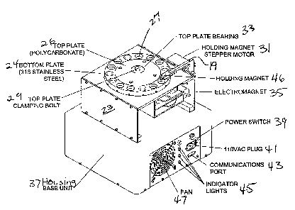
As illustrated in Figure 5, a commercial unit is shown
wherein the upper plate 26 is formed of a polymer such as
a polycarbonate and is mounted onto a bearing 33 and
secured with a clamping bolt 29. The legs support 22 are
replaced by flanges 23 forming a base. The lower plate 24
is formed of stainless steel. A holding magnet stepper
motor 31 rotates the top plate 26. The holding
electromagnet 46 is suspended over the upper cuvettes 27.
An electromagnet 35 is shown within the base. The base is
mounted onto a housing 37 which includes a power switch 39,
110VAC plug 41, communications port 43, indicator lights
45, and cooling fan 47.
More particularly, the laboratory unit includes a
computer and software, and consists of an electronics
housing and the processing unit. The electronics box has
several interface including 110VAC, power switch, RS 232
interface, and status lights. The unit receives power
through the 110AC connector. Power is activated with the
power switch. The PC that controls the unit operates via
the RS232 signal connector. The status of the power,
translating electromagnet, holding magnet, and plate
rotation are indicated with the GUI.
A single processing unit consists of hte upper and
lower plates, plate rotation system electromagnet,
CA 02366543 2001-10-04
WO 00/62034 PCT/US00/09610
-20-
electromagnet translation system, and holding magnet
assembly. The plates bolt together through a tapered
roller bearing that allows the plates to rotate with
respect to one another. The lapped interface between the
plates provides a seal separating the fluids. The lower
cuvette can be aligned with as many as 15 upper cuvette
stations during processing. A two phase stepping motor
rotates the upper plate by driving the rotation system that
engages an internal gear mounted to the underside o the
upper plate. The translating electromagnet is mounted to
the translation system that translates the electromagnet
along the lower cuvette. A programmed amount of current is
sent to the electromagnet creating magnetic field across
the lower cuvette. The translating electromagnet field
strength can be programmed from
0 to 1400 gauss (measured at the poleface), or other
selected range. The electromagnet translation system moves
the electromagnet up and down the lower cuvette. The
translation rates can be programmed to range from 5
micrometers/second to 2000 micrometers/second or other
selected values. The holding magnet assembly consists of
a permanent magnet mounted on an arm that is connect to a
stepping motor. The stepping motor rotates the arm
containing the holding magnet, positioning the holding
magnet about the cuvette being processed.
As best shown in Figure 6, one preferred embodiment of
a translating electromagnet 40 consists of a C-1018 steel
core 42 with 818 windings of 26-gage copper magnet wire
formed in a disc having an air gap 44 inbetween the distal
ends thereof. It receives current ranging from 0 to 2.16
Amps from the electronics box. The magnetic field strength
can be programmed from 0-006 gauss (measured at the
poleface). The electromagnetic system moves to
electromagnet up and down the lower cuvette 28. The
translation rates can be programmed to range from 120 - to
10 250
As best shown in Figure 4, the holding magnet 44
CA 02366543 2001-10-04
WO 00/62034 PCT/US00/09610
-21-
assembly consists of a permanent magnet mounted on an arm
19 that is connected to a stepping motor 31. The stepping
motor 31 rotates the azm 19 containing the holding magnet
44, positioning the holding magnet 44 above the upper
cuvette 27 being processed.
METHOD OF USE
MAGSEP 10 was designed to separate magnetically
susceptible materials suspended in fluids. In an
application of the embodiment shown in Figure 4 is as
follows:
The upper plate 26 and lower plate 24 are set to the
fill position (half stepped), and the fluid samples are
filled into the upper 27 and lower cuvettes 28. The upper
cuvette 27 rotates into position above the lower cuvette 28
aligning the upper 27 and lower cuvettes 28. The
translating electromagnet 40 energizes to a programmed
current level and translates from the bottom of the lower
cuvette 28 to the interf ace oz the piaLes ~~, ~d. um
translating electromagnet 40 is de-energized, and the
holding electromagnet 46 is energized to a programmed
current level pulling particles within a specified mobility
range into the top of the captured upper collection cuvette
27. Finally, the holding electromagnet 46 is de-energized
leaving the permanent holding magnet 44 to keep the
collected sample particles in the top cuvette 27 while the
upper plate 26 rotates thereby capturing the sample of the
collected particles. This process can be preprogrammed to
vary or remain the same for up to 15 capture cuvettes 27.
Figure 7 is a cross-section of the plate assembly
showing the bottom plate 24 in cooperative engagement with
the upper plate 26 in alignment with a sample cuvette 28
and an upper collection cuvette 27 and the holding magnet
44 well of the arm 19.
More particularly, Figure 8 shows the ffilling ports
within a section of a top plate 26 in fluid communication
CA 02366543 2001-10-04
WO 00/62034 PCT/US00/09610
-22-
with the upper collection cuvettes 27. The plate assembly
hods the samples before and after separation. The plate
assembly of one preferred embodiment consists of a
polycarbonate top plate, , a stainless steel bottom plate,
and one polycarbonate sample cuvette 28. The top plate is
bolted to the bottom plate with a clamping bolt that allows
the top plate to rotate. The top plate has at least one
and preferably a plurality, 15 as shown, of cavities call
collection cuvette 27. The sample cuvette 28 is attached
to an opening in the bottom plate 24. This allows the
collection cuvette 27 to be rotated over the sample cuvette
28, thus allowing particles in the sample cuvette 28 to be
transferred to the collection cuvette 27. The collection
cuvette can then be rotated away from the sample cuvette
capturing the contents of the collection cuvette. The
pressure of the clamping bolt seals the top plate to the
bottom plate.
Figures 9-14 show the step wise progression of
separating particles utilizing the present invention.
As shown in Figure 9, the cuvette configuration shows
the position of the capture cuvette 28, sample cuvette 38,
holding electromagnet 46, permanent holding magnet 44, and
translating electromagnet 40. Figure 10 illustrates
filling the sample cuvette 28 with cells or other substrate
having magnetic particles selectively attached thereto. As
shown in Figure 11, the top plate 26 rotates with respect
to the bottom plate 24 and the sample cuvette 28 to a full
step position. The translational electromagnet 40
energizes and moves toward the plate interface as depicted
in Figure 12 showing initiation of particle alignment in
the sample cuvette 28. It should be noted that the
sequence for filling can be to raise the translational
electromagnet 40 with the upper plate 26 one-half stepped,
then bring the upper collecting cuvette 27 holding the
magnet in place, or to bring the upper chamber 27 of the
cuvette and magnet 40 into place, then elevate the sample
cuvette 28. Figure
CA 02366543 2001-10-04
WO 00/62034 PCT/C1S00/09610
-23-
13 shows the final position of the translating
electromagnet and capture of particles wherein the
translating electromagnet 40 stops and deenergizes, and the
holding electromagnet 46 energizes, and field couples with
the permanent magnet 44. Finally, as shown in Figure 14,
the top plate 26 is rotated to capture a selected fraction
of the particles as the process sample.
Figure 15 is a graph depicting the translating
magnet 40 field strength of an embodiment such as described
in Figure 4.
As shown in Figure 16, the capture or holding
electromagnet 46 or programmable electromagnet is used to
pull the sample past the plate interface and into the top
of the upper cuvette 27.
The permanent magnet 44 is used to keep the captured
sample at the top of the capture cuvette 27, preventing it
from falling into the plate interface and becoming trapped
between the plates 24, 26. The permanent magnet 44 size
and materials can be varied to provide a variety of field
strengths.
Figure 17 is a graph showing the results of a
separation experiment separating magnet from non-magnetic
microparticles by the multistage magnetophoresis process.
The experiment began with a mixture containing 90% 1-2
Magnetic spheres ("animospheres, Polysciences) and 10% 6.0
non-magnetic spheres (IDC). The particles may be
suspended in any type of fluid; however, water,
polyethylene glycol, or ethyl alcohol are typically used.
Six cavities were equipped with magnets ranging from 10 mT
to 375 mT field at the pole face. Gradients were estimated
using field measurements at 2.54 cm and converted to mT/m.
Dwell time at each cavity was l5min, and travel distance
was on average 3mm. From these data, a magnetophoretic
mobility was estimated for each of the 7 cavities, as given
on the accompanying graph.
It is seen that 80.1% of the magnetic particles were
all captured in cavity #6, corresponding to a mobility of
CA 02366543 2001-10-04
WO 00/62034 PCT/US00/09610
-24-
0.6mm/N-s, where only 2.8% of the non-magnetic particles
were captured. The "purity" of the magnetic spheres went
from 90% to 99.6%.
Figure 18 is an exploded perspective view showing an
external plate assembly for a translating electromagnetic
station, wherein the plate assembly 100 includes a
translating electromagnetic station 102 (perferably 3 per
sample plate 104) is attached to a sample plate 104
rotational fluid communication with a plurality of cavities
106 formed and aligned around the periphery of a collection
plate 108 which is in cooperative engagement with a holding
magnet (electromagnet) 146.
Figure 19 is an exploded perspective view showing an
indexing system for MAGSEP for rotating the collection
plate, wherein a tray cover 110 attaches to the plate
assembly 100 which is connected to a worm gear 112 and
providing an angular contact bearing 114 connected to a
bearing standoff 116. The assembly is rotatively attached
to a base assembly 119 having a bearing race relief 118,
and position sensor 120, wherein the base 119 forms a tray
122 which is mechanical connection with shaft 124 of a
precision worm 126 in communication with a flexible shaft
coupling 128 driven be a stepper motor 130. The indexing
system is disposed within a cartridge or cassette 132
defined by a containment enclosure 134 and cover 136
holding the plate assembly as shown in Figure 20 which is
a perspective view showing a modular design of the
processing unit providing a cassette change out.
As shown in Figure 21, a MAGSEP cassette can be
utilized in a modular design including a processing module
holding more o the same or different cassettes.
As an alternate embodiment, Figures 22-24 show the use
of a cascading magnet system in which a series of dipole,
quadrupole or ring magnets, say three or four, is stacked
along the upper cylindrical cavity of the MAGSEP two-plate
device. These are activated in sequence, lowest first, to
accelerate (in the sense of a magnetic induction
CA 02366543 2001-10-04
WO 00/62034 PCTlUS00/09610
-25-
accelerator as used in particle physics) particles upward
until they reach an unstable point as defined by Earnshaw's
theorem, at which time the first field is switched off and
the second switched on to continue the upward capture
process without sticking the particles to the wall by
magnetapheresis as set forth and described in U.S. Patent
by Zborowski et al., 1995, hereby incorporated
by reference.
Figure 22 is an alternate embodiment showing a
translating magnet assembly utilizing multiple quadropole
magnets energized sequentially in a cascading magnet design
consisting of a sample cuvette, separation electromagnet,
collection cuvette, and holding electromagnet.
Figure 23 is a an alternate embodiment showing a
translating magnet assembly consisting of a moving
quadruple magnet consisting of a separation electromagnet,
sample cuvette, collection cuvette, and holding
electromagnet.
Figure 24 is an alternate embodiment showing a
quadruple or hexapole translating magnet.
ALTERNATE APPLICATIONS
The present invention could also be used for as a
means of "Magnetic Chromatography". Capture can be
isocratic, wherein magnets in all of the stages have equal
strength, or gradient wherein magnets at increasing stage
numbers have increasing field strength. In the latter
case, in a typical application the first stage would have
no magnet and no upper cavity and would serve the purpose
of homogenizing the cell mixture by stirring just before
the beginning of transfers . The second stage would have no
magnet and would serve the purpose of adding magnetic
particles to the cell suspension from a low volume upper
cavity, mixing them together, and allowing them to react.
The third stage would have a very weak magnet in the upper
cavity, which would have similar volume to the lower
cavity, and would attract only the most highly magnetized
CA 02366543 2001-10-04
WO 00/62034 PCT/US00/09610
-26-
cells, namely those with the most receptors for the
magnetic ligand. The fourth stage would have a stronger
magnet than does the third in its upper compartment and
would attract more-weakly magnetized cells, etc. until, at
the final-but-one stage the strongest magnet of all would
capture the cells with the lest receptors. The final stage
would also have no magnet and would contain any remaining
completely unmagnetized cells after the final transfer. In
the presence of gravity uncaptured cells will settle into
the lower cavities by gravitational sedimentation if the
transfer times are made sufficiently long. In the absence
of gravity uncaptured cells would remain in both the upper
and lower cavities at each transfer; however, continued
mixing with each transfer would have the effect of removing
the uncaptured cells in each cavity.
As another example, DYNABEADS M-280 are mixed with 2um
unmagnetized microspheres. Differential counts (Coulter
counter or hemacytometer) before and after are used to
determine the purification factor and resolution. To
determine the efficiency of the separation method on actual
cells, groups of cells with different quantities of beads
attached are separated with a gradient of magnetic field
strength (increasing with stage number). The substrate
consists of aldehyde-fixed human erythrocytes labeled with
amino paramagnetic particles, for example, Polysciences
#19524, after two levels of treatment with neuraminidse to
reduce the original negative surface charge by 30%, 60%,
and 0% (control). The resulting three populations of
erythrocytes bind amino paramagnetic spheres
electrostatically and separate into three fractions on the
multistage electromagnetic separator 10.
The foregoing detailed description is given primarily
for clearness of understanding and no unnecessary
limitations are to be understood therefrom, for
modification will become obvious to those skilled in the
art upon reading this disclosure and may be made upon
departing from the spirit of the invention and scope of the
CA 02366543 2001-10-04
WO 00/62034 _ 2~ _ PCT/US00/09610
T
mobility is defined as:
~c~B
g
dz
where B is the capture magnet's magnetic field strength and v°, is the
velocity of the particle in the
magnetic field. The velocity is a function of the magnetic field and
properties of the particle and the
solvcin:
a q Z u'-~xB dB
v -
b;~t r
hR4SEPdevite. ~
Therefore, each stage ' the -~eperi~rre~' -'~~--'-' '~~~ selected. particles
/of different
magnetophoretic mobilitie . The particles in each of the stages vpi~l ~a a a
different sa~~ldistnbution. h~9f er
The low magnetic field st ngths will select particles of larger~~~, whereas
they agnetic field
stren'ths will select for . Therefore, each stage will contain a
magnetophoretic
mobility cutoff, based on the magnetic field strength of the capture magnet,
and the dwell limo of the
capture. _'Ihe effects of magnetop orenc mo i ty on specific stages or t a
present expenm are
ov Figure 3. This fijure shows the relationship between the four stages
collecting t argest
number o articles to the starting material for the 95% cutoff diameters of
particles ptured. The
85 and 89 m ages contain particles larger than the starting material, in
effect 'ching the large
particles. These es had large magnetophoretic mobility cutoffs. The next t o
stages had smaller
magttetophoretic mo ' 'ty cutoffs and contained particles smaller than t
starting material. The
residual contained the . allest particles, which were smaller than
magnetophoretic mobility
cutoff for the last collection age.
4
g-lv4ateda
'
2
1
0
.
85 /89 91 ~ 107 Residual
Collection Magnet Strength
Z: 95 % cut-off di~neters captured by magnetic fields for selected
first step in eter~mining the magnetophoretic mobility cutoffs for each stag
's to determine BZ.
was do for the 85 mT capture magaet, and the result is shown in Figure 3. a
undisturbed
a done with the top plate removed from the MAGSEP, and suspen above the
eter. The magnet was placed in a well above a collection cavity. The measure
nts were
n from top of the collection cavity, z = 0 to z = 20 mm_ The disturbed field
map was
CA 02366543 2001-10-04
WO 00/62034 - 28 - PCT/US00/09610
Figure 7 shows the plate assembly used in the embodiment of Figure
i Figure 8 is a perspective view showing the plate assembly fill ports of the
embodiment of Figure
Figure 9 is a cuvette utilized in the embodiment of Figure 4 further showing a
capture cuvette and sample cuvette together with the holding electromagnet,
permanent
v holding magnet, and translating electromagnet;
is a artial cutawa view of the plate and a cuvette showing filing of the
sample cuvette;
Figure 11 is a partial cutaway view of the plate and a cuvette showing the
'fd P
position of the cuvette with respect to the rotation of theme plate;
Figure 12 is a partial cutaway view of the plate and a cuvette showing
initiation of
particle alignment in a sample cuvette due to the translation magnet
energizing and
moving particles toward the plate interface;
Figure 13 is a partial cutaway view of the plate and a cuvette showing
position of
the translation magnet and capture of particles;
Figure 14 is a partial cutaway view of the plate and a cuvette showing
rotation of
the top plate to capture a fraction of particles;
Figure 15 is a graph showing the translating magnet field strength;
Figure 16 shows the holding magnet assembly of the embodiment of Figure 4;
Figure 17 shows a graph depicting the separation of magnetic from non-magnetic
micro spheres;
Figure 18 is a perspective view showing a translating electromagnetic station
attached to an external plate assembly;
Figure 19 is a perspective view showing an indexing system for MAGSEP for
rotating the collection plate;
CA 02366543 2001-10-04
WO 00/62034 _ 29 _ PCT/US00/09610
Figure 20 is a perspective view showing a modular design of the processing
unit
providing a cassette change out;
Figure 21 is a perspective view showing a MAGSEP cassette occupying the
same form facto~s th ~~ight proven ADSEP cassette providing change out
capabilities;
Figure 22 is an alternate embodiment showing a translating magnet assembly
utilizing multiple quadropole magnets energized sequentially in a cascading
magnet
design;
Figure 23 is a an alternate embodiment showing a translating magnet assembly
consisting of a moving quadruple magnet; and
Figure 24 is an alternate embodiment showing a quadruple or hexapole
translating magnet.
DESCRIPTION OF THE PREFERRED EMBODIMENT
The present invention is an electromagnet separator 10 for quantitatively
separating substrates including cells, proteins, ligands, chemicals, antigens,
and other
particles by using an electromagnetically assisted separation process. The
multi-stage
electromagnet, ("MAGSEP"), 10 of the present invention allows a multiple stage
separation based on magnetic susceptility and magnetophoretic mobility. The
preferred
embodiment of the electromagnet separator 10 is a multistage counter-current
device in
which the substrates or cells are labeled with decreasing numbers of
paramagnetic
beads and separated quantitatively on the basis of the extent of labeling by
using
magnetic fields ~ increasing strength. The electromagnetic separator 10
enhances
product recovery~y collecting fractions automatically and provides
differential separation
where only binary separatior s were previously possible. It will wor~with
any~queous
[pr,..~..e..cr'w! ar~Itc4 bns AK
suspension and has the flexibility to operate efficiently innspace research
laboratories
CA 02366543 2001-10-04
WO 00/62034 _ 3p _ PCT/US00/09610
The invention makes it possible to
separate large quantities of immunological, hematological, and other
differentiating cell
types in direct proportion to their surface antigen content. Moreover, it
makes it
possible to either refine samples to a higher level or purity cyf categorize
portions of the
sample based on magnetic susceptibility and/or magnetophoretic mobility.
Moreover,
~e
the field strength ca Avaried to produce uniform capture of magnetized cells
or other
substrates.
Magnetophoretic mobility is defined as:
~~o~~~ where B is the capture magnet's magnetic field strength and vm is the
velocity of the
particle in the magnetic field. The velocity is a function of the magnetic
field and
properties of the particle and the solvent:
Therefore, each stage in the MAGSEP device selects particles of different
magnetophoretic mobilities. The particles in each of the stages will have a
different
hi'~~'
mobility distribution. The low magnetic field strengths will select particles
of J~a~gef
mobility, whereas the higher magnetic field strengths will select for lower
mobilities.
Therefore, each stage will contain a magnetophoretic mobility cutoff, based on
the
magnetic field strength of the capture magnet, and the dwell time of the
capture.
In equation (2) ~ is a particle radius, mX is the magnetic
susceptibility difference between particle and medium, ~ is
viscosity, and ~o is the magnetic permeability of free space.
The method of 'cell separation using a magnetic field has been implemented as
a
CA 02366543 2001-10-04
WO 00/62034 _ 31 _ PCT/US00/09610
binary separation between cells that have and have not bound magnetic micro
spheres
on the basis of a specific surface ligand, as best shown in Figure 1. As shown
an
antigen is attached to a cell receptor site and biotin is attached to the
antibody. A
magnetic bead is attached to avidin which is connected to the biotin.
Since biological cells that have on their surfaces receptors that can be bound
by an
antibody can be attached to magnetic particles through specific chemical
ligands such
as avidin, a protein that reacts with biotin, a ligand can be chemically bound
to the
antibody.
2 A
Figure ~ is a schematic representation of~ multistage
electromagnetic separator showing comparison with a hypothetical
magnetic chromatography column. As noted heretofore, the MAGSEP
~, device utilizes a step-wise rotary distribution and containment system
which selects,
y isolates, and stores particles of different magnetophoretic mobilities. The
particles in
each of the stages will have a different mobility distribution. The low
magnetic field
~~~~Er
strengths will select particles of layer mobility, whereas the higher magnetic
field
,, strengths will select for lower mobilities. Therefore, each stage will
contain a
t
magnetophoretic mobility cutoff, based on the magnetic field strength of the
capture
magnet~nd the dwell time of the capture. Figure 2 demonstrates that the fast
cells
L
have the greater magnetophoretic mobility. Thus; the cells are separated
according to
the quantity of ligand on their surfaces.
By combining magnetic attraction, used as a rate process,
with countercurrent extraction, it is possible to use magnetic
separation of cells as a quantitative technique separating on
the basis of the number of ligands bound per cell. This could
be qualitative, based on the amount of ligand bound to each kind
of cell, or quantitative, based on the amount of ligand bound to
CA 02366543 2001-10-04
WO 00/62034 _ 32 _ PCT/US00/09610
cells of the same type, some with high receptor content, and
some with low receptor content.
Figure 3 is a diagram showing a single stage of the
magnetic separation process whereby cells that bind magnetic
beads are drawn along the gradient toward the pole. The
illustration shows a magnetic source, either permanent or
electromagnets ~ at th ~ of the container or cuvette~ which
Ma
produces a magnetic f'~d gradient therein ~ ~orce~l creates
movement a~ the paramagnetic particles in accordance with
their magnetophoretic mobility. The electromagnetic separation
device 10 of the present invention provides a very clean
separation wherein the particles are loosely aligned in strata
with the most magnetic particles at the top of the cuvette,
S ~!
particles with a lower magnetic s ~ eptibAity are suspended in
the middle and particles ~ with little or no magnetic
susceptibility are suspended in the bottom of the cuvette.
For example, all separands attached to magnetized particles
such as cells or proteins may be drawn into a half-cavity of a
multistage separator from a uniform suspension, while non-
magnetic separands remain distributed equally between upper and
lower cavities. Nonmagnetic particles are allowed to settle for
a predetermined time period. The upper cavity is moved to a
position above a fresh solution that is thoroughly mixed with
the separated cells. In low gravity, the result may be achieved
not b~ sedimentation, but by dilution of non-magnetic cells out
of the/ tzpp~r cavit
CA 02366543 2001-10-04
WO 00/62034 - 33 - PCT/US00/09610
sample cavities within the same plate assembly. The field strengths of both
the
translating electromagnet and the holding electromagnet can also be varied
du~mg the
separation process.
Figure ~ is a perspective view of an embodiment of a
s multistage electromagnetic separator 10 of the present
invention. The MAGSEP unit IO illustrates the upper plate 26
r
rotatively coopeatively engaging a lower plate 24 supported by a
plurality of leg members 22 whereby the upper plate 26 contains
at least one and preferably a plurality of upper collection
to cuvettes 27 in selected fluid communication with the lower plate
24 and a lower sample cuvette 38 disposed therein wherein a.seal
is formed thereirbetween with a sealant such as a grease, wax,
or other lubricating andJor sealir_g constituent. Figured also
shows a translating electromagnet 40, a translation system 42, a
15 holding mzgnet 44 which is a permanent magnet in the
embodiment, a holding electromagnet with cooling fan 46, a plate
rotation system 48, and a plate location microswitches 50.
As illustrated in Figure 5, a commercial unit is shown
wherein the upper plate 26 is formed of a polymer such as a
2o polycarbonate and is mounted onto a bearing 33 and secured with
a clamping bolt 29. the legs support 22 are replaced by flanges
23 forming a base. The lower plate 24 is formed of stainless
s~eel. A holding magnet stepper motor 31 rotates the top plate
26. The holding electromagnet 46 is suspended over the upper
25 cuvettes 27. An electromagnet 35 is shown within the base. The
base is mounted onto a housing 37 which includes a power switch
CA 02366543 2001-10-04
WO 00/62034 - 34 - PCT/US00/09610
39, IlOVAC plug 41, communications port 43, indicator lights 45,
and cooling fan 47.
rlore particularly, the laboratory unit includes a computer and software,
and consists of an electronics housing and the processing unit. The
electronics box has
s several interfac~including 110VAC, power switch, RS 232 interface, and
status lights.
The unit receives power through the 110AC connector. Power is activated with
the
power switch. The PC that controls the unit operates via the RS232 signal
connector.
The status of the power, translating electromagnet, holding magnet, and plate
rotation
are indicated with a graph i ~ c, ~ a r e~ i ..~~'~'G ~ m
~efsoH~1 c,.~pv.~e.r
~o A single processing unit consists of ~ upper and lower plates, plate
rotation
system electromagnet, electromagnet translation system, and holding magnet
assembly. The plates bolt together through a tapered roller bearing that
allows the
plates to rotate with respect to one another. The lapped interface between the
plates
provides a seal separating the fluids. The lower cuvette can be aligned with
as many as
s 15 upper cuvette stations during processing. A iwo~hase stepping motor
rotates the
upper plate wing the rotation system that engages an internal gear mounted to
the
undersid o~t upper plate. The translating electromagnet is mounted to the
Ver+~tw~,y
translation system that translates the electromagnet~along ~e lower cuvette. A
programmed amount of current is sent to the electromagnet creating magnetic
field
zo across the lower cuvette. The translating electromagnet field strength can
be
programmed fro
0 to 1400 gauss (measured at the poleface), or other selected range. The
electromagnet translation system moves the electromagnet up and down the lower
cuvette. The translation rates can be programmed to range from 5
micrometers/second
as to 2000 micrometers/second or other selected values. The holding magnet
assembly
consists of a permanent magnet mounted on an arm 'that is connect to a
stepping
CA 02366543 2001-10-04
WO 00/62034 - 35 - PCT/US00/09610
motor. The stepping motor rotates the arm containing the holding magnet,
positioning
~e
the holding magnet abo~ the cuvette being processed.
As best shown in Figure 6, one preferred embodiment of a translating
electromagnet 40 consists of a C-9018 steel core 42 with 818 windings of
26~age
s copper magnet wire formed in a dis~having an air gap 44 inbetween the distal
ends
thereof. It receives current ranging from 0 to 2.16 Amps from the electronics
box.. The
I 1;'o n
magnetic field strength can be pro rammed from 0--6~ gauss (measured at the
~ Y,~-rG.ni~a~ t o v~ ~ ~ .___
poleface). The electromagnet~system moves electromagnet up and down the lower
cuvette 28. The translation rates can be programmed to range from 120 ~to 2b0~
~~s
to As best shown in Figure 4, the holding magnet 44 assembly consists of a
permanent magnet mounted on an arm 19 that is connected to a stepping motor
31.
The stepping motor 31 rotates the arm 19 containing the holding magnet 44,
positioning
the holding magnet 44 above the upper cuvette 27 being processed.
15 METHOD OF USE
MAGSEP 10 was designed to separate magnetically susceptible materials
suspended in fluids. Ixf an application of the embodiment shown in Figure 4 is
as
follows:
~o The upper plate 26 and lower plate 24 are set to the fill position (half
stepped),
and the fluid samples are filled into the upper 27 and lower cuvettes 28. The
upper
cuvette 27 rotates into position above the lower cuvette 28 aligning the upper
27 and
lower cuvettes 28. The translating electromagnet 40 energizes to a programmed
current leve) and translates from the bottom of the lower cuvette 28 to the
interface of
zs the plates 24, 26. The translating electromagnet 40 is de-energized, and
the holding
electromagnet 46 is energized to a programmed current level pulling particles
within a
CA 02366543 2001-10-04
WO 00/62034 - 36 - PCT/US00/09610
specified mobility range into the top of the captured upper collection cuvette
27. Finally,
the holding electromagnet 46 is de-energized leaving the permanent holding
magnet 44
to keep the collected sample particles in the top cuvette 27 while the upper
plate 26
rotates thereby capturing the sample of the collected particles. This process
can be
preprogrammed to vary or remain the same for up to 15 capture cuvettes 27.
Figure 7 is a cross-section of the plate assembly showing the bottom plate 24
in
cooperative engagement with the upper plate 26 in alignment with a sample
cuvette 28
and an upper collection cuvette 27 and the holding magnet 44 well of the arm
19.
More particularly. Figure 8 shows the filling ports within a section of a top
plate
~0 26 in fluid communication with the upper collection arvettes 27. The plate
assembly
ho~s the samples before and after separation. The plate assembly of one
preferred
embodiment consists of a polycarbonate top plate, stainless steel bottom
plate, and
one polycarbonate sample cuvette 28. The top plate is bolted to the bottom
plate with a
G..evvrAl se~r~tras a.. o,xlc and wv~ r~te~ k~ ~'t~. bo4trow. Pla.Et
~clamping bolt that allows the top plate to rotate. The top plate has at least
one and
preferably a plural ~, 15 as shown, of cavities cai~collection cuvett~ 27. The
sample
cuvette 28 is attached to an opening in the bottom plate 24. This allows the
collection
cuvette 27 to be rotated over the sample cuvette 28, thus allowing particles
in the
sample cuvette 28 to be transferred to the collection cuvette 27. The
collection cuvette
can then be rotated away from the sample cuvette capturing the contents of the
zo collecfion cuvette. The pressure of the clamping bolt seals the top plate
to the bottom
plate.
Figures 9-14 show the step-wise progression of separating particles utilizing
the
present invention.
AS Shown in Figure 9, the cuvette configuration shows the position
25 of the capture cuvette 28, sample cuvette 38, holding
electromagnet 46, permanent holding magnet 44, and translating
CA 02366543 2001-10-04
WO 00/62034 _ 3'7 _ PCT/US00/09610
electromagnet 40. Figure 111 illustrates filling the sample
Cuvette 28 with cells or other substrate having magnetic
particles selectively attached thereto. As shown in Figure 11,
the top plate 26 rotates with respect to the bottom plate 24 and
Wig S~.~nnp~- ~i~ t~ 11?catl7~1 Gu.rP_.~EtS ~.~Gil~ e~~i gw~
the sample cuvette 28 to a full step positio ~ ~he
translational electromagnet 40 energizes and moves toward the
plate interface as depicted in Figure i2 showing initiation of
particle alignment in the sample cuvette 28. It should be noted
that the sequence for filling can be to raise the translationai
io electromagnet 40 with the upper plate 26 one-half stepped, then
bring the upper collecting cuvette 27 holding the magnet in
place, or to bring the upper chamber 2'7 of the cuvette and
magnet 4o into place, then elevate the sample cuvette 28.
Figure
is 13 shows the final position of the translating electromagnet and
capture of particles wherein the translating electromagnet 4D
stops and deenergizes, and the holding electromagnet 46
energizes, and field couples with the permanent magnet 44.
Finally, as shown iri Figure 14, the top plate 26 is rotated to
2o capture a selected fraction of the particles as the process
sample.
Figure 15 is a graph depicting the translating magnet
40 field strength of an embodiment such as described in Figure
4.
i5 As shown in Figure 16, the~capture or holding electromagnet
46 or programmable electromagnet is used to pull the sample past
CA 02366543 2001-10-04
WO 00/62034 _ 3g _ PCT/US00/09610
the plate interface and into the top of the upper cuvette 27.
The permanent magnet 44 is used to keep the captured sample
at the top of the capture cuvette 27, preventing it from fading
into the plate interface and becoming trapped between the plates
s 24, 26. The permanent magnet 44 size and materials can be
varied to provide a variety of field strengths.
Figure I7 is a graph showing the results of a separation
_G
experiment separating magnets from non-magnetic microparticles by
the multistage magnetophoresis process. The experiment began
so with a mixture containing 90% 1-2~"~ Magnetic spheres
lnG.
(~~ani ospheres, Polyscienc ~) and 10~ 6.0 ~w. non-magnetic
~r.~'~aci al nr ~~4rm't s ~a~
spheres ~-. The particles may be suspended in any type of fluid; however,
water, polyethylene glycol, or ethyl aicvhol are typically used. Six cavities
were
equipped with magnets ranging from 10 mT to 375 mT field at the
is pole face. Gradients were estimated using Tield measurements at
2.54 cm and converted to mT/m. Dwell time at each cavity was
l5min, and travel distance was on average 3mm. From these data,
a magnetophoretic mob~iity was estimated for each of the 7
cavities, as given on the accompanying graph.
2o It is seen that 80.1% of the magnetic particles were all
captured in cavity #6, corresponding to a mobility of 0.6mm/N-s,
where only 2.s% of the non-magnetic particles were captured.
The ~~purity" of the magnetic spheres went from s0% to 99.s%.
Figure 18 is an exploded perspective view showing an extema! plate assembly
25 for a translating electromagnetic station, wherein the plate assembly 100
includes a
translating electromagnetic station 102 (r erably 3 per sample plate 104)
~ttached
CA 02366543 2001-10-04
WO 00/62034 - 39 - PCT/US00/09610
W
to a sample plate 104~rotational fluid communication with a plurality of
cavities 106
formed and aligned around the periphery of a collection plate 108 which is in
cooperative engagement with a holding magnet (electromagnet) 146.
Figure 19 is an exploded perspective view showing an indexing system for
s MAGSEP for rotating the collection plate, wherein a tray cover 110 attaches
to the plate
assembly 100 which is connected to a worm gear 112 and providing an angular
contact
bearing 114 connected to a bearing standoff 116. The assembly is rotatively
attached
to a base assembly 119 having a bearing race relief 118, and position sensor
120,
wherein the base 119 forms a tray 122 which is mechanical connection with
shaft 124 of
.o a precision worm 126 in communication with a flexible shaft coupling 128
driven be a
stepper motor 130. The indexing system is disposed within a cartridge or
cassette 132
defined by a containment enclosure 134 and cover 136 holding the plate
assembly as
shown in Figure 20 which is a perspective view showing a modular design of the
processing unit providing a cassette change out.
As shown in Figure 21,4a ~MAGSEP cassette can be utilized in a modular design
including a processing module holding more o~the same or different cassettes.
As an alternate embodiment, Figures 2?~ho ~ the use of a cascading magnet
system in which a series of dipole, quadrupole or ring magnets, say three or
four, is
stacked along the upper cylindrical cavity of the MAGSEP two-plate device.
These are
Zo activated in sequence, lowest first, to accelerate (in the sense of a
magnetic induction
accelerator as used in particle physics) particles upward until they reach an
unstable
point as defined by Eamshaw's theorem, at which time the first 'field is
switched off and
the second switched on to continue the upward capture process without sticking
the
particles to the wall by magnetapheresis as set forth and described in U.S.
Patent
z5 SWS3. Z ~'i' ~ by Zborowski et al., 1995, hereby incorporated by reference.
~-~,a
Figure 2is .a~i~altemate embodiment showing a translating magnet assembly
~o
CA 02366543 2001-10-04
WO 00/62034 _ 4p _ PCT/US00/09610
utilizing multiple quadropole magnets energized sequentially in a cascading
magnet
design consisting of a sample cuvette, separation electromagnet, collection
cuvette, and
holding electromagnet.
Figure 23 is ~n alternate embodiment showing a translating magnet assembly
s consisting of a moving quadruple magnet consisting of a separation
electromagnet,
sample cuvette. collection cuvette, and holding electromagnet.
Figure 24 is an alternate embodiment showing a quadruple or hexapole
translating magnet.
:o ALTERNATE APPLICATIONS
The present invention could also be used f~as a means of uMagnetic
Chromatography". Capture can be isocratic~ wherein magnets in al( of the
stages have
equal strength, yr ~gradient~~wherein magnets at increasing stage numbers have
increasing field strength. In the latter case, in a typical application the
first stage would
15 have no magnet and no upper cavity and would serve the purpose of
homogenizing the
cell mixture by stirring just before the beginning of transfers. The second
stage would
have no magnet and would serve the purpose of adding magnetic particles to the
cell
suspension from a low volume upper cavity, mixing them together, and allowing
them to
read. The third stage would have a very weak magnet in the upper cav'dy, which
would
Zo have similar volume to the lower cavity. and would attract only the most
highly
magnetized cells, namely those with the most receptors for the magnetic
ligand. The
fourth stage would have a stronger magnet than does the third in its upper
compartment
and would attract more weakly magnetized cells, etc~ until, at the final-but-
one stage the
strongest magnet of all would capture the cells with the 1~ t receptors. The
final stage
zs would also have no magnet and would contain any remaining completely
unmagnetized
cells after the final transfer. In the presence of gravity uncaptured cells
will settle into
CA 02366543 2001-10-04
WO 00/62034 - 41 - PCT/US00/09610
the lower .cavities by gravitational sedimentation ~ the transfer times are
made
sufficiently long. fn the absence of gravity uncaptured cells would remain in
both the
upper and lower cavities at each transfer; however, continued mixing w'tth
each transfer
would have the effect of n:movin~ the uncaptured cells in each cavltyr.
The foregoing detailed description is given primarily for
clearness of understanding and no unnecessary limitations are to be
understood therefrom, for modification will become obvious to those
skilled in the art upon reading this disclosure and may be made upon
departing from the spirit of the invention and scope of the appended
claims. Accordingly, this invention is not intended to be limited by
the specific exemplifications presented herein above. Rather, what
is intended to be covered is within the spirit and scope of the
appended claims.