Language selection

Search

Patent 2366605 Summary

Third-party information liability

Some of the information on this Web page has been provided by external sources. The Government of Canada is not responsible for the accuracy, reliability or currency of the information supplied by external sources. Users wishing to rely upon this information should consult directly with the source of the information. Content provided by external sources is not subject to official languages, privacy and accessibility requirements.

Claims and Abstract availability

Any discrepancies in the text and image of the Claims and Abstract are due to differing posting times. Text of the Claims and Abstract are posted:

  • At the time the application is open to public inspection;
  • At the time of issue of the patent (grant).
(12) Patent: (11) CA 2366605
(54) English Title: CHECK VALVE WITH OVERSIZED BILL
(54) French Title: CLAPET DE NON-RETOUR A BEC SURDIMENSIONNE
Status: Term Expired - Post Grant Beyond Limit
Bibliographic Data
(51) International Patent Classification (IPC):
  • F16K 15/00 (2006.01)
  • F16K 15/14 (2006.01)
(72) Inventors :
  • RAFTIS, SPIROS G. (United States of America)
  • ABROMAITIS, ANDRE T. (United States of America)
  • DUER, MICHAEL J. (United States of America)
(73) Owners :
  • RED VALVE CO., INC.
(71) Applicants :
  • RED VALVE CO., INC. (United States of America)
(74) Agent: WILSON LUE LLP
(74) Associate agent:
(45) Issued: 2004-10-12
(22) Filed Date: 2002-01-04
(41) Open to Public Inspection: 2003-07-04
Examination requested: 2002-04-30
Availability of licence: N/A
Dedicated to the Public: N/A
(25) Language of filing: English

Patent Cooperation Treaty (PCT): No

(30) Application Priority Data: None

Abstracts

English Abstract

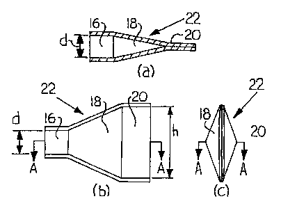
A check valve having an upstream inlet part mountable on a discharge end of a conduit, a downstream outlet part adapted to prevent backflow of fluid through the check valve, and a transition part located between the upstream inlet part and the downstream outlet part. A longitudinal dimension of the downstream outlet part extending in a direction transverse to a direction of flow is at least approximately 1.57 times the diameter of the upstream inlet part.


French Abstract

Un clapet de non-retour présentant une partie d'admission en amont montable sur une extrémité de décharge d'un conduit, une partie de sortie en aval conçu pour empêcher le reflux de liquide par le clapet de non-retour, et une partie de transition située entre la partie d'admission en amont et la partie de sortie en aval. Une dimension longitudinale de la partie de sortie en aval s'étendant dans une direction transversale à une direction du flux fait au moins environ 1,57 fois le diamètre de la partie d'admission en amont.

Claims

Note: Claims are shown in the official language in which they were submitted.


We claim:
1. A check valve, comprising:
an upstream inlet part mountable on a discharge
end of a conduit;
a downstream outlet part adapted to prevent
backflow of fluid through the check valve;
a transition part located between the upstream
inlet part and the downstream outlet part;
a longitudinal dimension of the downstream
outlet part extending in a direction transverse to a
direction of flow being greater than approximately 1.57
times the diameter of the upstream inlet part; and
wherein the downstream outlet part is
symmetrical about a horizontal longitudinal plane through
the downstream outlet part, the longitudinal plane
coincident with the center line of the upstream inlet
part.
2. The check valve of claim 1, further
comprising a flange on the upstream inlet part.
3. The check valve of claim 1, wherein the
check valve is made at least in part from an elastomeric
material.
-9-

4. The check valve of claim 3, further
comprising a synthetic reinforcement in the elastomeric
material.
5. The check valve of claim 1, wherein the
upstream inlet part is made at least in part from a
stiff, durable material.
6. The check valve of claim 1, wherein the
upstream inlet part further includes a polyester fabric
reinforcement.
7. The check valve of claim 1, further
including local reinforcements selected from the group
consisting of embedded wire, plates, rings, and tubes.
8. The check valve of claim 1, wherein, in
operation, the downstream outlet part will open to
approximately 40% to 85% of the area of a full circular
opening.
9. A check valve, comprising:
an upstream inlet part mountable on a discharge
end of a conduit;
-10-

a downstream outlet part adapted to prevent
backflow of fluid through the check valve;
a transition part located between the upstream
inlet part and the downstream outlet part;
a longitudinal dimension of the downstream
outlet part extending in a direction transverse to a
direction of flow being greater than approximately 1.57
times the diameter of the upstream inlet part; and
wherein the downstream outlet part is
symmetrical about a vertical longitudinal plane through
the downstream outlet part, the longitudinal plane
coincident with the center line of the upstream inlet
part.
10. The check valve of claim 9, further
comprising a flange on the upstream inlet part.
11. The check valve of claim 9, wherein the
check valve is made at least in part from an elastomeric
material.
12. The check valve of claim 11, further
comprising a synthetic reinforcement in the elastomeric
material.
-11-

13. The check valve of claim 9, wherein the
upstream inlet part is made at least in part from a
stiff, durable material.
14. The check valve of claim 9, wherein the
upstream inlet part further includes a polyester fabric
reinforcement.
15. The check valve of claim 9, further
including local reinforcements selected from the group
consisting of embedded wire, plates, rings, and tubes.
16. The check valve of claim 9, wherein, in
operation, the downstream outlet part will open to
approximately 40% to 85% of the area of a full circular
opening.
17. A check valve, comprising:
an upstream inlet part mountable on a discharge
end of a conduit;
a downstream outlet part adapted to prevent
backflow of fluid through the check valve;
a transition part located between the upstream
inlet part and the downstream outlet part;
-12-

a longitudinal dimension of the downstream
outlet part extending in a direction transverse to a
direction of flow being greater than approximately 1.57
times the diameter of the upstream inlet part; and
wherein the downstream outlet part is pre-
formed to define a curvilinear bill.
18. The check valve of claim 17, further
comprising a flange on the upstream inlet part.
19. The check valve of claim 17, wherein the
check valve is made at least in part from an elastomeric
material.
20. The check valve of claim 19, further
comprising a synthetic reinforcement in the elastomeric
material.
21. The check valve of claim 17, wherein the
upstream inlet part is made at least in part from a
stiff, durable material.
-13-

22. The check valve of claim 17, wherein the
upstream inlet part further includes a polyester fabric
reinforcement.
23. The check valve of claim 17, further
including local reinforcements selected from the group
consisting of embedded wire, plates, rings, and tubes.
24. The check valve of claim 17, wherein, in
operation, the downstream outlet part will open to
approximately 40% to 85% of the area of a full circular
opening.
25. A method for reducing headloss in a
conduit in a drainage system, including the steps of:
providing a check valve comprising an upstream
inlet part mountable on a discharge end of the conduit,
a downstream outlet part adapted to prevent backflow of
a fluid through the check valve, a transition part
located between the upstream inlet part and the
downstream outlet part, and a longitudinal dimension of
the downstream outlet part extending in a direction
transverse to a direction of flow being greater than
approximately 1.57 times the diameter of the upstream
inlet part; and
-14-

directing fluid through the conduit, in the
upstream inlet part, through the transition part, and out
the downstream outlet part.
-15-

Description

Note: Descriptions are shown in the official language in which they were submitted.


CA 02366605 2002-O1-04
CHECK VALVE WITH OVERSIZED BILL
BACKGROUND OF THE INVENTION
1. Field of the Invention
The present invention relates to a check valve
of the so-called "duckbill" type for use in drainage
systems and effluent outfall Lines.
2. Description of the Prior Art
A check valve is essentially a valve which
allows fluid to flow in only one direction through a
conduit, while closing and preventing back or reverse
flow, when back pressure builds up downstream of the
valve to a level greater than the upstream fluid pressure
head. Check valves are used in various fluid
transportation operations and must include some means of
allowing the forward flow of liquid yet preventing any
backflow.
Conventional rubber duckbill check valves have
an inlet cuff, an outlet bill and a transitional_middle
part for connecting the cuff and the bill. The bill
comprises a slit which opens when fluid is forced through
the valve. Typically, existing "duckbill" type check
valves have a bill slit dimension that is equal to or
less than one-half the cuff (inlet) circumference. The
reason for this is that if the bill slit dimension is
larger than one-half the circumference of the cuff
diameter, it becomes difficult or even impossible to

CA 02366605 2002-O1-04
remove a one-piece mandrel, which is used to manufacture
the check valve through the cuff.
In most applications, it is desirable to have
the maximum flow through the valve at the lowest possible
pressure drop in the forward direction of the flow or, in
other words, the lowest possible headloss. To improve
the performance of duckbill check valves, valves have
been recently developed in which the width of the bill is
larger than the diameter of the cuff. The output area
and the open position of the bill thus approaches more of
the inlet area of the cuff, and the headloss decreases.
For example, U.S. Patent No. 5;931,197 to Raftis et al.
discloses an asymmetrical check valve of this type.
It is therefore an object of the present
invention to provide a duckbill check valve with an
improved headloss over conventional valves. It is
another object of the present invention to provide a
check valve that overcomes the design problems
encountered in the prior art.
2 0 SU1~IARY OF THE INVENTION
The present invention is a check valve with an
oversized bill. The present invention includes a tubular
inlet part, an outlet part and a transitional middle
part, connecting the inlet part with the outlet part,
wherein the width or height of the outlet part is at
-2-

CA 02366605 2002-O1-04
least approximately 1.57 times the diameter of the inlet
part. The outlet part may be symmetrical about a
longitudinal plane through the check valve. It can also
have a curved bill.
The advantage of a valve of this size is the
low headloss compared to conventional duckbill check
valves. With an effective outlet area larger than the
inlet area of the valve, the headloss will drop below the
headloss of an open pipe end at high flow rates.
The invention itself, both as to its
construction and its method of operation, together with
the additional objects and advantages thereof, will best
be understood from the following description of specific
embodiments when read in connection with the accompanying
drawings.
BRIEF DESCRIPTION OF THE DRAWINGS
Fig. la shows a top view of a conventional
duckbill check valve according to the prior art;
Fig, lb shows a side view of the conventional
duckbill check valve of Fig. la according to the prior
art;
Fig. lc shows a front view of the conventional
duckbill check valve of Fig. la according to the prior
art;
-3-

CA 02366605 2002-O1-04
Fig. 2a shows a top view of another
conventional duckbill check valve according to the prior
art;
Fig. 2b shows a side view of the conventional
duckbill check valve Fig. 2a according to the prior
of
art;
Fig. 3a shows a top view of an embodiment
according to the present invention;
Fig . 3b shows a side view of the embodiment of
Fig. 3a according to the present invention;
Fig. 3c shows a front view of the embodiment of
Fig. 3a according to the present invention;
Fig. 4 shows a front view of the present
invention in a closed position;
Fig. 5 shows a front view of the present
invention in a slightly opened position;
Fig. 6 shows a front view of the present
invention in a further opened position;
Fig. 7 shows a front view of the present
invention in a fully opened position;
Fig. 8 shows a perspective view of the present
invention with a curvilinear-shaped outlet part; and
Fig. 9 shows a side sectional view of the
present invention attached to a pipeline via a flange.
-4-

CA 02366605 2002-O1-04
DETAILED DESCRIPTION OF THE PREFERRED EMBODIMENT
Figs. 1 and 2 both show conventional duckbill
check valves. These valves comprise an inlet portion 10,
a transitional portion 12 and an outlet portion 14. The
advantages of these designs are the low tooling costs and
simple removal of a mandrel from the completed part. The
check valve shown in Fig. 2 is slightly widening, with
the width of the outlet portion 14 approximately equal to
one-half the circumference of the inlet portion 10. The
mandrel is slightly more difficult to remove from the
completed valve, but the headloss is lower.
After extensive testing at the Water Research
Laboratories of Utah State University, it was determined
that for submerged discharge, the headloss of a
"duckbill" type of check valve is very closely equal to:
H=QZ / 19 . 5gA2
where H = Headloss in feet of water,
Q = Quantity of water flowing in gallons per minute,
g = Gravitational constant = 32.16 feet/sec2, and
A = Effective open area in square inches:
Therefore, for constant flow conditions, the
headloss is inversely proportional to the discharge area
squared.
It was found that with a width or height
(depending upon orientation) of the outlet portion 14 at
-5-

CA 02366605 2002-O1-04
least approximately 1.57 times the diameter of the inlet
part, the headloss is much smaller than the headloss of
conventional check valves. The present invention is a
duckbill check valve 22 with an enlarged bill, as shown
in Fig. 3. The duckbill check valve 22 comprises an
inlet part 16, a transitional part 18 and an outlet part
20, which appears as a pair of lips facing and engaging
one another. The height h of the outlet part 20 (or
bill) of Fig. 3 is substantially larger than the diameter
d of the inlet part 16. In fact, the height of the
outlet part 20, in its closed position, should be at
least approximately 1.57 times the diameter d of the
inlet part 16.
It is important to note that the outlet part 20
may be oriented in different positions, rotatable about
an axis perpendicular to the pipeline 30. Fig. 3 shows
the outlet part 20 of the present invention wherein the
outlet part 20 (or lips) is oriented in a vertical
manner, making the height h the operative dimension.
Turning to Figs. 4-7, the outlet part 20 is oriented in
a horizontal manner, making the width w the operative
dimension. According to the invention, it is the
longitudinal dimension of the outlet part, in its closed
position, that must be substantially larger than the
diameter d of the inlet part 16.
-6-

CA 02366605 2002-O1-04
Figs. 4-7 show the different opening stages of
a duckbill check valve 22 according to the present
invention. Fig. 4 shows a closed duckbill check valve
22, Figs. 5 and 6 show a progressively open duckbill
check valve 22 and Fig. 7 shows a fully open duckbill
check valve 22. As can be seen from Fig. 7, depending on
valve stiffness, the outlet part 20 will not open to a
full circular opening, but will open to approximately 40%
to 85% of the area of a full circular opening.
Valves built in accordance with the present
invention, with an outlet part 20 bill slit greater than
1.57 times the inlet part 16 bore diameter, will have an
open area about equal to, or larger than, the area of the
inlet part 16. Thus, the headloss is considerably lower
than the headloss of conventional valves. Again, it is
the width w of the outlet part 20 (in Figs. 4-8) that
should be at least approximately 1.57 times the diameter
d of the inlet part.
The duckbill check valve 22 is preferably made
from an elastomer, such as neoprene, or an elastomer
reinforced with synthetic fabric, such as nylon or
polyester, with construction similar to an automobile
tire. The inlet part 16 is generally made of a stiff,
durable material; such as styrene butadiene, with
polyester fabric reinforcing, whereas the outlet part 20
-7-

CA 02366605 2002-O1-04
is made of a flexible material to allow proper opening
and closing of the outlet part 20. Further, the outlet
part 20 may be symmetrical about a longitudinal plane A-A
through the duckbill check valve 22. This longitudinal
plane A-A is coincident with a center line of the inlet
part 16. In addition, it is also envisioned that the
outlet part 20 may be curvilinear, as described in U.S.
Patent No. 5,727,593. The inlet part 16 may be fitted
with a flange 32, instead of the cuff shown in the
drawings.
A duckbill check valve according to the
preferred embodiment is manufactured similarly to a tire,
using a multiple-piece mandrel. The mandrel will have to
be disassembled to remove it from the inside of the
valve. However, the great reduction in headloss will
justify the added expense of manufacturing the invention.
Furthermore, the duckbill check valve 22 can be provided
with local reinforcements, such as embedded wire, plates,
rings and tubes.
It will be understood by those of ordinary
skill in the art that modifications may be made without
departing from the spirit and scope of the' present
invention.
_g_

Representative Drawing
A single figure which represents the drawing illustrating the invention.
Administrative Status

2024-08-01:As part of the Next Generation Patents (NGP) transition, the Canadian Patents Database (CPD) now contains a more detailed Event History, which replicates the Event Log of our new back-office solution.

Please note that "Inactive:" events refers to events no longer in use in our new back-office solution.

For a clearer understanding of the status of the application/patent presented on this page, the site Disclaimer , as well as the definitions for Patent , Event History , Maintenance Fee  and Payment History  should be consulted.

Event History

Description Date
Inactive: Expired (new Act pat) 2022-01-04
Maintenance Fee Payment Determined Compliant 2020-01-15
Inactive: Late MF processed 2020-01-15
Common Representative Appointed 2019-10-30
Inactive: Late MF processed 2019-01-09
Letter Sent 2019-01-04
Inactive: Agents merged 2018-02-19
Inactive: Office letter 2018-02-19
Revocation of Agent Request 2017-12-29
Appointment of Agent Request 2017-12-29
Inactive: Office letter 2016-11-28
Inactive: Adhoc Request Documented 2016-11-28
Appointment of Agent Request 2016-11-03
Revocation of Agent Request 2016-11-03
Inactive: Payment - Insufficient fee 2011-12-29
Inactive: IPC from MCD 2006-03-12
Grant by Issuance 2004-10-12
Inactive: Cover page published 2004-10-11
Inactive: Final fee received 2004-07-27
Pre-grant 2004-07-27
Letter Sent 2004-05-18
Notice of Allowance is Issued 2004-05-18
4 2004-05-18
Notice of Allowance is Issued 2004-05-18
Inactive: Approved for allowance (AFA) 2004-04-19
Application Published (Open to Public Inspection) 2003-07-04
Inactive: Cover page published 2003-07-03
Amendment Received - Voluntary Amendment 2002-07-18
Letter Sent 2002-06-17
Request for Examination Received 2002-04-30
Request for Examination Requirements Determined Compliant 2002-04-30
All Requirements for Examination Determined Compliant 2002-04-30
Inactive: First IPC assigned 2002-02-19
Inactive: Filing certificate - No RFE (English) 2002-02-04
Letter Sent 2002-02-04
Application Received - Regular National 2002-02-04

Abandonment History

There is no abandonment history.

Maintenance Fee

The last payment was received on 2004-01-05

Note : If the full payment has not been received on or before the date indicated, a further fee may be required which may be one of the following

  • the reinstatement fee;
  • the late payment fee; or
  • additional fee to reverse deemed expiry.

Patent fees are adjusted on the 1st of January every year. The amounts above are the current amounts if received by December 31 of the current year.
Please refer to the CIPO Patent Fees web page to see all current fee amounts.

Owners on Record

Note: Records showing the ownership history in alphabetical order.

Current Owners on Record
RED VALVE CO., INC.
Past Owners on Record
ANDRE T. ABROMAITIS
MICHAEL J. DUER
SPIROS G. RAFTIS
Past Owners that do not appear in the "Owners on Record" listing will appear in other documentation within the application.
Documents

To view selected files, please enter reCAPTCHA code :


To view images, click a link in the Document Description column (Temporarily unavailable). To download the documents, select one or more checkboxes in the first column and then click the "Download Selected in PDF format (Zip Archive)" or the "Download Selected as Single PDF" button.

List of published and non-published patent-specific documents on the CPD .

If you have any difficulty accessing content, you can call the Client Service Centre at 1-866-997-1936 or send them an e-mail at CIPO Client Service Centre.

({010=All Documents, 020=As Filed, 030=As Open to Public Inspection, 040=At Issuance, 050=Examination, 060=Incoming Correspondence, 070=Miscellaneous, 080=Outgoing Correspondence, 090=Payment})


Document
Description 
Date
(yyyy-mm-dd) 
Number of pages   Size of Image (KB) 
Representative drawing 2002-06-02 1 8
Abstract 2002-01-03 1 17
Description 2002-01-03 8 287
Claims 2002-01-03 7 163
Drawings 2002-01-03 3 54
Courtesy - Certificate of registration (related document(s)) 2002-02-03 1 113
Filing Certificate (English) 2002-02-03 1 164
Acknowledgement of Request for Examination 2002-06-16 1 179
Reminder of maintenance fee due 2003-09-07 1 106
Commissioner's Notice - Application Found Allowable 2004-05-17 1 161
Notice of Insufficient fee payment (English) 2011-12-28 1 93
Maintenance Fee Notice 2019-01-08 1 181
Late Payment Acknowledgement 2019-01-08 1 166
Courtesy - Acknowledgement of Payment of Maintenance Fee and Late Fee (Patent) 2020-01-14 1 431
Fees 2004-01-04 1 34
Correspondence 2004-07-26 1 34
Fees 2004-12-14 1 29
Correspondence 2016-11-02 3 129
Courtesy - Office Letter 2016-11-27 138 5,840
Courtesy - Office Letter 2018-02-18 1 33