Language selection

Search

Patent 2366835 Summary

Third-party information liability

Some of the information on this Web page has been provided by external sources. The Government of Canada is not responsible for the accuracy, reliability or currency of the information supplied by external sources. Users wishing to rely upon this information should consult directly with the source of the information. Content provided by external sources is not subject to official languages, privacy and accessibility requirements.

Claims and Abstract availability

Any discrepancies in the text and image of the Claims and Abstract are due to differing posting times. Text of the Claims and Abstract are posted:

  • At the time the application is open to public inspection;
  • At the time of issue of the patent (grant).
(12) Patent: (11) CA 2366835
(54) English Title: METHOD OF TREATING ZIPPER TO REMOVE CAMBER
(54) French Title: METHODE DE TRAITEMENT DES FERMETURES A GLISSIERE POUR ENLEVER LA CAMBRURE
Status: Expired and beyond the Period of Reversal
Bibliographic Data
(51) International Patent Classification (IPC):
  • A44B 19/42 (2006.01)
  • A44B 19/16 (2006.01)
  • B21D 25/00 (2006.01)
  • B21D 53/50 (2006.01)
(72) Inventors :
  • MACHACEK, ZDENEK (United States of America)
(73) Owners :
  • ILLINOIS TOOL WORKS INC.
(71) Applicants :
  • ILLINOIS TOOL WORKS INC. (United States of America)
(74) Agent: FINLAYSON & SINGLEHURST
(74) Associate agent:
(45) Issued: 2005-07-05
(22) Filed Date: 2002-01-03
(41) Open to Public Inspection: 2002-08-06
Examination requested: 2002-01-03
Availability of licence: N/A
Dedicated to the Public: N/A
(25) Language of filing: English

Patent Cooperation Treaty (PCT): No

(30) Application Priority Data:
Application No. Country/Territory Date
09/777,949 (United States of America) 2001-02-06

Abstracts

English Abstract


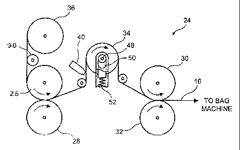
A method and apparatus for removing camber from zipper with profiles having
interlocking elements and or webs. The zipper is stretched longitudinally in a
manner so that the
interlocking elements stretch relative to each other. To this end, the zipper
is fed to an idler
wheel that may be spring loaded. From a set of first drive wheels and fed from
the idler wheel
by a set of second drive wheels. The second drive wheels are driven faster
than the first drive
wheels to effect the stretching. Alternately only the second set of drive
wheels are driven and
the stretch is provided by the spring loaded idler wheel or the zipper is
driven around a static
curved surface.


Claims

Note: Claims are shown in the official language in which they were submitted.


The embodiments of the invention in which an exclusive property or privilege
is
claimed are defined as follows:
1. A method of treating a zipper having mated interlocking members and a least
one web
on each side of said mated interlocking members to remove camber in the
zipper, said method
comprising stretching the mated interlocking members relative to each other.
2. The method in accordance with claim 1 wherein the interlocking members are
stretched around a curved surface.
3. The method in accordance with claim 1 wherein the direction in which said
members
are interlocked is generally at 90 degrees to a stretching direction.
4. The method in accordance with claim 1 wherein the direction of stretching
the zipper
is opposite to a direction in which the zipper was wound on a spool.
5. A method of treating a zipper having mated interlocking members to remove
camber
in the zipper comprising the steps of:
feeding a length of said zipper from a spool at a first speed to an idler
roller;
passing said zipper around said idler roller, and then feeding the zipper at a
second
speed from said idler roller, said second speed being greater than said first
speed so as to
stretch one interlocking member of said zipper relative to another
interlocking member of the
zipper.
7

6. The method in accordance with claim 5 wherein a surface of said idler
roller is
contoured to outside dimensions of said interlocking members.
7. The method in accordance with claim 5 comprising the further step of
tensioning said
idler roller as said zipper passes around it.
8. The method in accordance with claim 5 comprising the further step of
heating said
zipper prior to passing said zipper around said idler roller.
9. The method in accordance with claim 1 comprising the further step of
heating said
zipper prior to stretching the mated interlocking members relative to each
other.
10. A method of treating a zipper having mated interlocking members to remove
camber
in the zipper comprising the steps of:
feeding a length of said zipper from a spool to an idler roller;
passing said zipper around said idler roller;
spring loading said idler roller;
feeding said zipper to a second set of rollers and driving said second set of
rollers so
as to stretch one interlocking member of the zipper relative to the other
interlocking member
of the zipper.
8

Description

Note: Descriptions are shown in the official language in which they were submitted.


CA 02366835 2002-O1-03
769-271
The present invention relates to reclosable packaging and, in particular to a
method for
treating zipper used in the production of such packaging to remove camber from
the zipper.
Reclosable packaging is becoming increasingly more popular as primary
packaging for
food stui~s and other commodities. One reason for the growing popularity of
such packaging is
the development of form, fill and seal (FFS) equipment which lends itself to
rapid and mass
production of packages with advanced feattues, such as reclosability combined
with hermetic
tends to develop cwvature or camber. This is caused by the dii~erence in
diameter between the
interlocking profiles when wound around tha core of a spool. The lower profile
or the profile
closest to the core has a smaller diam~er than the engaged profile above it.
This difference is
more acute at the locations closests to the core. Even. after the zipper is
attached to the film, the
camber remains, particularly when the film is relatively flexible. Thin causes
alignment and
other problems in the production process and could lead to an unsightly and
sometimes
unworkable package.
6?OZ3HA01011801

CA 02366835 2004-09-08
SUMMARY OF THE ~VENTION
In view of the above, the present invention seeks to provide a method of
treating
zipper to remove such camber in the zipper.
Further, the invention seeks to provide such a method that can be practiced at
any
point in the production of the reclosable packaging but preferably after the
formed zipper is
un-spooled but before it is sealed in place.
Still further, the invention seeks to provide such a process that employs
relatively
simple equipment to remove camber that results from the zipper spooling.
Accordingly, in accordance with the present invention, camber is removed from
a spool
wound zipper, by stretching the zipper longitudinally around a curved surface
so the interlocking
elements are stretched relative to each other. Generally the zipper
interlocking elements are
stretched against a surface that is in a plane of about 90 degrees to the
direction in which the
elements interlock. In other instances to further help remove the camber, the
zipper may be
driven around the curved surface in a direction opposite to that in which it
had been wound on
the spool. To this end, a set of drive rolls drives a zipper that was wound on
a spool past a
curved surface, with the zipper fitting into a groove in the curved surface
shaped to
accommodate it. A set of guide rollers maintain pressure on the zipper and
hold it in position.
Alternately the zipper is fed to an idler wheel from a set of first drive
wheels and fed from the
idler wheel by a set of second drive wheels. The second drive wheels are
driven faster than the
first drive wheels to effect the stretching. The idler wheel can be spring
loaded with a calibrated
spring to add additional stretch to the zipper. Alternately only the second
set of wheels are used
2

CA 02366835 2002-O1-03
to drive the zipper, with the spring loaded idler wheel providing the required
stretch. The rim of
the idler wheel has a center channel in which the profiles' interlocking
members ride and the
center channel has sides that wil! accommodate the zipper shape.
~R1EF DESC,'RIPTION O~~THE DRAWI ~1G
In the accompanying drawings:
Fig. 1 is a top schematic view of a device for removing camber in accordance
with the
present invention;
Fig. 2 is an ~larged side elevational view of one of the fast set of drive
wheels;
. v: g~; 3 is an enlarged side elevational knew of the profile section of oine
~of the set of drive. .
wheels for a zipper with taperodvsides; -
Fig. 4 is a side elevational of a length of zippar prior to the camber being
removed;
Fig. 5 is a top plan view of an alternate device; and
Fig. 6 is a fragmentary and a~larged sectional view of the profile groove.
3

CA 02366835 2004-09-08
DETAILED DESCRIPTION OF THE PREFERRED EMBODllVIENT
Reference is now made to the drawings and to Fig.4 in particular wherein a
length of
zipper as used in the formation of reclosable plastic bags is depicted. While
such zipper may
take on many shapes and configurations, the representative zipper depicted
consists of two
profiles 12, 14 with each profile consisting of an interlocking element 16, 18
and a web 20, 22.
Many variations are well known in the art for such profiles such as the shapes
of the interlocking
elements, and the number and position of the webs. What is common to the
various types of
profiles is that the interlocking elements of each set of profiles are
designed to engage and
disengage with each other. In addition, where the zippers are provided with
webs, the mass of
the interlocking elements is substantially greater (on the order of ten times
more) than the mass
of the profile webs.
A device 65 for removing such camber is depicted in Fig. 5. A curved surface
64 is
provided-with the zipper being driven around it by rolls 66. The zipper is fed
from a spool 67
and is held in place by guide rolls 68. The curved surface 64 is provided with
a groove such as
depicted in Fig. 3, formed to accommodate the zipper shape. As the zipper is
driven around the
curved surface, one interlocking element of the zipper is stretched relative
to the other.
In another arrangement, a device 24 for removing such camber is depicted in
Fig. 1. The
device consists of a first set of drive wheels 26, 28 a second set of drive
wheels 30, 32 and a
spring loaded idler wheel 34. The zipper 10 is fed from a spool 36 past guide
38 to the first set
of drive wheels 26, 28. The zipper then passes around the idler wheel 34 to
the second set of
drive wheels 30, 32. The second set of drive wheels 30, 32 is driven at a
slightly greater speed
4

CA 02366835 2002-O1-03
than the first set of drive wheels 26, 28. As a resuh the zipper 10 is
maintained in tension and
stretched as it passes over the idler wheel 34. Alternately, only the second
set of drive wheels
drive the zipper past the spring loaded idler wheel, with the spring
calibrated to provide the
amount of stretch required to remove the camber.
A heater 40 may be provided upstream of the idler wheel to soften the zipper
before it
passes around the idler wheel and thereby facilitate the stretching to which
the zipper will be
subjected. By stretching one imerlocking profile relative to the other around
idler wheel 34 the
camber in the zipper is removed. A groove 42 is provided in the rim of the
various wheels
configured to the zipper shape to capture the zipper interlocking element 16,
18. The gooves
may vary in shape according to their function. In this instance the rim also
tapes outwardly on
both sides of the gcoovc to provide support 44, 46 for :the webs, 20 and 22 of
the zipper: The . , ,
y : ,'..
idler wheel shaft 48 rides in a slot SO ru a frame of the dev~ae and is biased
by a spring 52. As a
result, constant or additional tension can be maiatained, or added on the
zipper as it passes
around the idler wheel that leads to longihrdinally atret~ the profiles
interlocking mem>~rs
relative to each other. The groove provided in the feed-in drive wheels 26,
28, the feed-ofd' drive
wheels 30, 32 and the spring loaded idler wheel 34 are depicted in Fig. 3. As
shown the rims of
the drive wheels and idle wheels are flat or tapered depending on the zippy
construction, except
for a groove 54 for the interlocking members.
As is depicted in Fig. 6 the interlocking elements 16 sect 18, open and close
in the
direction shown by the arrows and this directioa is at right angles to the
stretching direction
being applied to the elements as they ride around the curved surface 69.

CA 02366835 2002-O1-03
By stretching the interlocking member of the zipper relative to each other the
camber is
removed from the zapper. The camber removal device is best placed immediately
upstream of
the bag making equipment so as to remove any camber that will have built up in
the zipper as a
result of being spooled.
6

Representative Drawing
A single figure which represents the drawing illustrating the invention.
Administrative Status

2024-08-01:As part of the Next Generation Patents (NGP) transition, the Canadian Patents Database (CPD) now contains a more detailed Event History, which replicates the Event Log of our new back-office solution.

Please note that "Inactive:" events refers to events no longer in use in our new back-office solution.

For a clearer understanding of the status of the application/patent presented on this page, the site Disclaimer , as well as the definitions for Patent , Event History , Maintenance Fee  and Payment History  should be consulted.

Event History

Description Date
Time Limit for Reversal Expired 2008-01-03
Letter Sent 2007-01-03
Inactive: IPC from MCD 2006-03-12
Grant by Issuance 2005-07-05
Inactive: Cover page published 2005-07-04
Pre-grant 2005-04-15
Inactive: Final fee received 2005-04-15
Letter Sent 2004-10-18
4 2004-10-18
Notice of Allowance is Issued 2004-10-18
Inactive: Approved for allowance (AFA) 2004-10-05
Amendment Received - Voluntary Amendment 2004-09-08
Inactive: S.30(2) Rules - Examiner requisition 2004-04-16
Inactive: S.29 Rules - Examiner requisition 2004-04-16
Application Published (Open to Public Inspection) 2002-08-06
Inactive: Cover page published 2002-08-05
Inactive: IPC assigned 2002-03-07
Inactive: First IPC assigned 2002-03-07
Inactive: IPC assigned 2002-03-07
Inactive: Filing certificate - RFE (English) 2002-02-05
Letter Sent 2002-02-05
Application Received - Regular National 2002-02-05
Request for Examination Requirements Determined Compliant 2002-01-03
All Requirements for Examination Determined Compliant 2002-01-03

Abandonment History

There is no abandonment history.

Maintenance Fee

The last payment was received on 2004-12-22

Note : If the full payment has not been received on or before the date indicated, a further fee may be required which may be one of the following

  • the reinstatement fee;
  • the late payment fee; or
  • additional fee to reverse deemed expiry.

Patent fees are adjusted on the 1st of January every year. The amounts above are the current amounts if received by December 31 of the current year.
Please refer to the CIPO Patent Fees web page to see all current fee amounts.

Fee History

Fee Type Anniversary Year Due Date Paid Date
Application fee - standard 2002-01-03
Registration of a document 2002-01-03
Request for examination - standard 2002-01-03
MF (application, 2nd anniv.) - standard 02 2004-01-05 2003-12-23
MF (application, 3rd anniv.) - standard 03 2005-01-04 2004-12-22
Final fee - standard 2005-04-15
MF (patent, 4th anniv.) - standard 2006-01-03 2005-12-30
Owners on Record

Note: Records showing the ownership history in alphabetical order.

Current Owners on Record
ILLINOIS TOOL WORKS INC.
Past Owners on Record
ZDENEK MACHACEK
Past Owners that do not appear in the "Owners on Record" listing will appear in other documentation within the application.
Documents

To view selected files, please enter reCAPTCHA code :


To view images, click a link in the Document Description column (Temporarily unavailable). To download the documents, select one or more checkboxes in the first column and then click the "Download Selected in PDF format (Zip Archive)" or the "Download Selected as Single PDF" button.

List of published and non-published patent-specific documents on the CPD .

If you have any difficulty accessing content, you can call the Client Service Centre at 1-866-997-1936 or send them an e-mail at CIPO Client Service Centre.

({010=All Documents, 020=As Filed, 030=As Open to Public Inspection, 040=At Issuance, 050=Examination, 060=Incoming Correspondence, 070=Miscellaneous, 080=Outgoing Correspondence, 090=Payment})


Document
Description 
Date
(yyyy-mm-dd) 
Number of pages   Size of Image (KB) 
Representative drawing 2002-03-07 1 7
Description 2002-01-02 6 243
Abstract 2002-01-02 1 23
Claims 2002-01-02 3 94
Drawings 2002-01-02 3 45
Description 2004-09-07 6 222
Claims 2004-09-07 2 58
Drawings 2004-09-07 3 45
Representative drawing 2005-06-15 1 9
Acknowledgement of Request for Examination 2002-02-04 1 178
Courtesy - Certificate of registration (related document(s)) 2002-02-04 1 113
Filing Certificate (English) 2002-02-04 1 164
Reminder of maintenance fee due 2003-09-03 1 106
Commissioner's Notice - Application Found Allowable 2004-10-17 1 160
Maintenance Fee Notice 2007-02-13 1 172
Correspondence 2005-04-14 1 29