Note: Descriptions are shown in the official language in which they were submitted.
CA 02366923 2001-10-02
WO 00/63042 PCT/CA00/00381
FILL LIMIT CONTROL VALVE ASSEMBLY HAVING A LIQUID FUEL TRAP
Field of the Invention
The present invention relates to a valve which controls the fuel level, the
venting
and traps fuel vapors from an automotive vehicle fuel tank to a fuel canister,
or the like,
and which prevents escape of liquid fuel from the fuel tank in the event of
rollover of the
vehicle.
Background of the Invention
A fill limit control valve, which is normally disposed in a vehicle fuel tank,
frequently comprises a housing having a valve portion for sealing engagement
about a
hole in a fuel tank and a float portion extending into the fuel tank. The type
of valve to
which the subject invention pertains responds to the level of liquid fuel in
the fuel tank,
staying open to vent vapor as long as the fuel level is below a predetermined
level. These
are sometimes referred to as "fill control" or "shutoff' valves, since closing
thereof creates a
sudden pressure increase in the tank thereby preventing further refueling.
The valve portion defines a vent opening for venting vapors from the fuel tank
and a
vapor outlet for conveying fuel vapors to a vapor canister. A float is movably
supported by
the float portion for seating, against and closing the vent opening in
response to the float rising
to a predetermined fuel level. Examples of such prior art assemblies are shown
in U. S. Patent
Nos. 5,590,697 to Benjey et al. and 5,860,458 to Benjey et al.
Sometimes these valves are supplementedwith a gravity-responsiverollover
device
supported at the bottom of the float portion for engaging and moving the float
upwardly to
seal the vent opening in response to a predetermined amount of deviation from
vertical, e.g., a
rollover. An example of such a prior art assembly is shown in U.S. Patent No.
5,809,976 to
Cook et al.
Although all of these assemblies may perform satisfactorily, liquid fuel may
inadvertently pass through the valve and into the vapor canister. Influx of
liquid into the
vapor canister, can prematurely saturate the canister and pollute the
environment. Hence,
there remains a need to reduce and virtually eliminate the amount of liquid
fuel that passes
out of the valve during normal operation.
-1-
CA 02366923 2001-10-02
WO 00/63042 PCT/CA00/00381
Summary of the Invention
The disadvantages of the prior art may be overcome by providing a fill limit
control
valve assembly disposed in a vehicle fuel tank. The fill limit control valve
assembly has a
housing having a valve portion for connection to a fuel tank and a float
portion for extending
into the fuel tank. The valve portion defines a vent opening for venting
vapors from the fuel
tank. A float is movably supported by the float portion for movement between
an open
position spaced from the vent opening and a closed position seating against
and sealing the
vent opening in response to the float rising to a predetermined fuel level. A
liquid fuel trap is
disposed above the vent opening to limit liquid fuel flow through the vapor
outlet.
Accordingly, the subject invention provides a fill limit control valve that
minimizes
and virtually eliminates the undesirable flow of liquid fuel into a vapor
canister. Hence, only
fuel vapors pass through the valve and into the canister.
According to another aspect of the invention, there is provided a fill limit
control
valve assembly having a float which traps vapor during normal fuel filling to
enable the float
to become buoyant and responsively move to a closed position and which
collects liquid fuel
when in an inverted rollover condition to prevent buoyancy and responsively
move to the
closed position.
Brief Description of the Drawings
Other advantages of the present invention will be readily appreciated as the
same
becomes better understood by reference to the following detailed description
when considered
in connection with the accompanying drawings wherein:
Figure 1 is an environmental view showing the subject invention combined with
an
automotive vehicle fuel tank;
Figure 2 is perspective view of a fill limit control valve in accordance with
the subject
invention;
Figure 3 is an enlarged perspective view in cross section of the subject valve
in an
open position;
Figure 4 is an enlarged perspective view in cross section of the subject valve
in a
closed position; and
Figure 5 is an enlarged perspective view in cross section of the subject valve
in a
closed and rollover position.
-2-
CA 02366923 2001-10-02
WO 00/63042 PCT/CA00/00381
Detailed Description of the Preferred Embodiment
Refernng to the Figures, wherein like numerals indicate like or corresponding
parts
throughoutthe several views, a fill limit control valve assembly is generally
shown at 10
disposed within a vehicle fuel tank 12 in Figure 1.
The valve assembly 10 includes a housing, generally indicated at 14, having a
float
portion, generally indicated at 18, adapted for extending into the fuel tank
12. The housing 14
includes a mounting cap 20 defining a vapor outlet connector 22 for conveying
vapors to a
vapor canister 24 via line 26. A recirculationpipe 21 is also provided on the
cap 20 for
recirculating vapors into a filler neck 23 via a second line 25. In addition,
a rollover valve 27
may be mounted to the fuel tank 12 and connected to the vapor canister 24 as
is known in the
art.
The mounting cap 20 has a mounting face which abuts the fuel tank 12 to secure
the
valve assembly 10 to the fuel tank 12 in any suitable manner. The vapor
canister 24, which is
typically a carbon canister, rollover valve 27, and fuel tank 12 are of any
suitable design as is
known in the art. For illustrative purposes, the lines 25, 26 are shown
schematically.
Referring to Figure 2, the float portion 18 is a cylindrical column and
includes a float
30 movably supportedtherein. The float portion 18 defines a number of openings
82, 83 for
providing fluid communicationbetween the fuel tank 12 and the float 30. As
illustrated, the
openings 82 have a rectangular configuration and opening 83 has a triangular
configuration.
Preferably there are two rectangular openings 82 and two triangular openings
83 diametrically
opposed on the float portion 18.
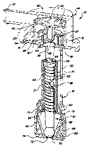
Referring to Figures 3 and 4, the valve assembly 10 also includes a valve
portion 16,
adapted for connection to the fuel tank 12. The mounting cap 20 encompasses at
least a
portion of the valve portion 16. The valve portion 16 defines a vent opening
28 for venting
vapors from the fuel tank 12 to the vapor canister 24 via outlet connector 22
and line 26.
The valve assembly 10 is characterized by a liquid fuel trap disposed above
the vent
opening 28 to limit liquid fuel flow through the outlet connector 22. The fuel
trap includes a
baffle barrier 32 surrounding the vent opening 28. A return cup 34 having a
base 36 overlies
the baffle barrier 32 with a depending rim 38 surrounding the baffle barner 32
for forcing the
flow of vapor from the vent opening 28 through a U-turn. The return cup 34
includes legs 48
extending downwardly from the rim 3 8 to support the fuel trap in the valve
portion 16. The
return cup 34 also includes a bullet 46 extending from the base 36 thereof and
into the baffle
-3-
CA 02366923 2001-10-02
WO 00/63042 PCT/CA00/00381
barrier 32 to define an annular passage for dividing the flow of vapors from
the vent opening
28. The bullet 46 extends above the base 36 of the return cup 34 and an
annular flange 50
extends radially of the bullet 46. The flange 50 has passages 52 therethrough
for the passage
of vapors through the flange 50. The return cup 34, base 36, bullet 46, legs
48, and flange 50
preferably define an integral discriminatormember. The discriminatormember
preferably is
formed of a homogeneous organic polymeric material. As appreciated, the
discriminator
member may include multiple separate parts and may be formed of any suitable
material.
The valve portion 16 includes a bottom 40 supporting the baffle barrier 32 and
defining the vent opening 28. The bottom 40 of the integral casing defines an
annular valve
seat 64 extending or projecting downwardly. An outer wall 42 extends from the
bottom 40
and is spaced from and surrounds the rim 3 8 for defining a collection
reservoir for liquid fuel.
The baffle barner 32 includes drain holes 44 for draining liquid from the
reservoir back
through the vent opening 28. The baffle barrier 32, bottom 40 and outer wall
42 are all
defined by an integral casing, preferably formed of an organic polymeric
material. The
integral casing may include multiple separate parts and may be formed of any
suitable
material.
The legs 48 of the return cup 34 extending downwardly to the bottom 40 for
supporting the return cup 34, as well as the entire discriminator member, on
the bottom 40.
The annular flange 50 engages the outer wall 42 to further support the
discriminatormember
to the wall 42 of the valve portion 16.
The mounting cap 20 surrounds the outer wall 42 of the casing and defines the
vapor
outlet connector 22 for conveying vapors from the passages 52 in the annular
flange 50 of the
discriminator member. The integral casing and the cap 20 include a first
tongue and groove
connection 76 interconnectingthe integral casing and the cap 20.
The float portion 18 defines a float cavity in which the float 30 is
vertically movable
between an open position spaced from the vent opening 28 and a closed position
seating
against and sealing the vent opening 28. The float cavity is defined by an
extension of the
integral casing which extends downwardly from the bottom 40. The float 30
includes a
buoyant cylindrical section 31 having a closed top end connected to the top of
a stem or shaft
54. The cylindrical section 31 is hollow with an open lower end and includes
diametrically
opposed openings 86 for allowing liquid to pass into a hollow interior of the
cylindrical
section 31. Openings 86 are spaced from the closed upper end of cylindrical
section 31 so
-4-
CA 02366923 2001-10-02
WO 00/63042 PCT/CA00/00381
that a vapor chamber is defined having a sufficient volume to enable the float
30 to float in
response to the filling liquid fuel.
A valve seal 56 is secured to the upper closed end of the cylindrical section
31 for
sealing engagement with the vent opening 28 to close the float 30 when in the
closed position.
As illustrated, the seal 56 is flexible and snapped into engagement with a
button integral with
the top end of the cylindrical section 31. Preferably, the seal 56 engages the
valve seat 64,
which extends into the float cavity. The stem 54 extends from the top end of
the cylindrical
section 31 of the float 30 downwardly to a lower end 58.
A guide disk 60 extends about the lower end of the float cavity and has an
opening
receiving the stem 54 for guiding and stabilizing movement of the float 30 in
the float cavity.
The guide disk 60 includes openings 84 for allowing liquid to pass
therethrough between the
funnel-shaped element 68 and the float cavity. A spring 62 acts between the
guide disk 60
and the top of the stem 54 for biasing the stem 54, as well as the entire
float 30, toward the
closed position.
Referring also to Figure 5, a skirt 66 depends from the float portion 18 of
the integral
casing. A gravity responsive device 67 is supported in the skirt 66 of the
float portion 18.
The gravity responsive device 67 is supported below the guide disk 60 for
engaging the distal
end 58 of the stem 54 and for moving the float 30 upwardly to seal with the
seat 64 and close
the vent opening 28 in response to a predetermined amount of deviation from
vertical.
The gravity responsive device 67 includes a funnel shaped element 68 extending
from
a large diameter adjacent the guide disk 60 to a small diameter at the bottom
thereof. A ball-
seat opening 70 is defined in the small diameter and a ball 72, preferably
made of steel, is
normally disposed over the ball-seat opening 70. A support wheel 74 extends
radially from
the small diameter to engage the skirt 66 to support the funnel-shaped element
68 in the skirt
66. The guide disk 60 is also supported in the skirt 66. A second tongue and
groove
connection 78 interconnects the disk 60 and the skirt 66. The wheel 74 and the
funnel-shaped
element 68 are integral and consist of an organic polymeric material and
include a third
tongue and groove connection 80 interconnectingthe wheel 74 and the skirt 66.
The invention provides a fill limit control valve assembly with an integrated
liquid/vapordiscriminatormember. During normal refilling of the fuel tank 12,
the fuel level
in the tank 12 rises and vapor is displaced. This causes a constant vapor flow
to the canister
24. In particular, the vapors pass through the openings 82 and upwardly
through the float
-5-
CA 02366923 2001-10-02
WO 00/63042 PCT/CA00/00381
cavity. The vapors then pass through the vent opening 28 and are then diverted
by the bullet
46. The vapors pass over the baffle barrier 32 between the barrier 32 and base
36. The
vapors are forced to complete a U-turn by the depending rim 38. The vapors
then continue
upward through the passages 52 in the flange 50 and out through the connector
22 and into
the vapor canister 24. The vapors are purified by the canister 24 and
exhausted to the
atmosphere.
The baffle barrier 32, in conjunction with the return cup 34, condenses fuel
and fuel
mist that travels with the vapor flow and retains any liquid in the reservoir
established
between the wall 42 and the baffle barrier 32. As appreciated, a small amount
of fuel mist
and/or liquid may become trapped in the reservoir. This retained mist and/or
liquid drains
back into the tank 12 through the drain holes or slits 44 in the baffle
barrier 32 once the vent
opening 28 is reopened.
During normal filling of the fuel tank 12, at least a portion of the liquid
fuel also
passes through the openings 82 and into the float cavity. The liquid fuel also
passes through
openings 84 in the guide disk 60 such that liquid fuel is accumulating below
and within the
float 30. In particular, liquid fuel is disposed between the stem 54 and the
cylindrical section
31. The displaced vapor within the float 30 passes out of opening 86 within
the cylindrical
section 31. This process continues until the level of liquid fuel within the
fuel tank 12 reaches
the level above the opening 86 in the cylindrical section 31. At this point,
no additional
vapors can pass through the opening 86 and the vapors disposed between the top
of the
cylindrical section 31 and the opening 86 are trapped within the upper end of
the hollow
interior of the cylindrical section 31, thereby increasing the buoyancy of the
float 30 allowing
the float 30 to move responsively upwardly to the closed position.
As the level of liquid in the fuel tank 12 continues to rise, the float 30
will move from
the open position, as shown in Figure 3, to the closed position, as shown in
Figure 4. The
upward movement of the float 30 occurs because of the buoyancy of the float
30, created by
the trapped vapor, in relation to the rising liquid and the upward pushing
force from the
spring 62. Hence, when a predetermined level of fuel in the tank 12 is
reached, the float 30
completely rises and, with the assistance of the spring 62, seals the seat 64
with the seal 56.
The float 30 is therefore movably supported by the float portion 18 for moving
to the closed
position seating against and sealing the vent opening 28 in response to the
float 30 rising to a
predeterminedfuel level, i.e., full.
-6-
CA 02366923 2001-10-02
WO 00/63042 PCT/CA00/00381
Upon closure of the vent opening 28, the fuel tank 12 no longer has an exhaust
avenue
for the vapor such that pressure builds up in the tank 12 and corresponding
filler neck 23.
This pressure build-up triggers the filling nozzle to shut off and stops the
refilling of the fuel
tank 12.
As the liquid fuel in the fuel tank 12 is used, the level of liquid fuel will
lower which
subsequently lowers the float 30 within the float cavity. As appreciated, the
liquid fuel will
flow out of the float cavity through the openings 82. When the float 30
lowers, the vent
opening 28 is reopened such that any trapped mist and liquid can flow back
into the float
cavity through the drain holes 44. The surface tension of the fuel in the
float 30 would cause
the fuel to remain in the cylindrical float 30 except that the stem 54 helps
to purge the fuel by
breaking this surface tension.
During a vehicle rollover, the steel ball 72 will disengage from the ball-seat
opening
70. Preferably, the steel ball 72 starts to roll out of the normal position
when the vehicle is
tilted more than 70 ° . As the steel ball 72 moves upward along the
funnel-shaped element, the
ball 72 engages the distal end 58 of the stem 54 to push the stem 54 into the
closed position
sealing the fuel tank 12. As appreciated, the ball 72 may be of any suitable
design, material
and weight so long as the stem 54 is adequately pushed upward against the
valve seat 64.
During the rollover, the cylindrical section 31 of float 30 will be in an
inverted condition and
will therefore fill with liquid fuel such that the float 30 is no longer
buoyant. The float 30 is
responsively forced to the closed position, against the valve seat 64 by the
spring 62
preventing fuel from passing through opening 28.
Many modifications and variations of the present invention are possible in
light of the
above teachings. The invention may be practiced otherwise than as specifically
described
within the scope of the appended claims.
_7_