Note: Descriptions are shown in the official language in which they were submitted.
CA 02366987 2002-O1-09
SLAB AND COIL RAILCAR
BACKGROUND OF THE TNV~~N
1. Field of tlZe, Inventio,~
[OOOI] The present invention relates to railcars for carrying slabs of various
materials.
More particularly, the present invention relates to a railcar for carrying
steel slabs as well as
steel coils. Most particularly, the present invention relates to a railcar for
carrying steel slabs
having an increased carrying capacity, easier loading and rlnloading, and
having steel Coil
carrying capabilities.
2. Descnsption of the Prig Art
[0002] Presently, steel slabs are often shipped on 52'- 6" Mill Gondola cars.
The
loading and unloading of the steel slabs from the Mill Gondola cars is not as
sufficiently
efficient as if might be. Large, heavy, cylindrical objects, and particularly
coils of rolled
steel, are also commonly transported on a flatcar or a troughed car. Either
type of car has a
cargo bed supported on a center sill or similar structure naming the length of
the cat. The
individual coils are chained or otherwise restrained in place. Withi regard to
railcars designed
specifically for carrying coils, the prior art is somewhat voluminous.
[0043] Known railcar arrangements for hauling coils of various materials are
disclosed, for example, in U.S. Patent Nos. 2,977,900; 3,009,426; 3,186,357;
3,291,072;
4,451,188; and 4,077,005.
[0004] U.S. Patent No. 2,997,900 shows a railcar for transporting steel coils.
A
cover is used on a gondola car with cradles formed in the bottom of the car to
retain the steel
coils. The body of the gondola-car includt~s a narrov~r platform along the
outer edge of the car.
[0005] U.S. Patent No. 3,291,072 discloses a support sysiem for carrying
different
sized coils. The outer support members are fixed at a downward slope. The two
inner support
members are hinged at both ends so that they can be inverted to divide a
single large storage
position intotwa smaller storage positions.
[0006] ll.S. Patent No. 3,1.86,357 shows a side sill and top flange
arrangement.
Planks extend the leagth of the car and extend at a downward. angle from the
side sills to a
center sill. This forms a cradle that is an integral part of the car
structure.
[DD07[ U.S. Patent No. 3,009,426 shows a railcar fnr transporting steel coils
that
include a hinged cover to enclose the steel coils. 'Wooden planks run the
length of the cradle
and are bolted to angled members. The wooden planks define the surface of the
trough,
which engages the steel coil. The cover is split down the middle and is hinged
at the outer
CA 02366987 2002-O1-09
edges. The cower rotates to permit coils to be loaded from the top or from the
ends of the
enclosure.
[0008] U.S. Patent No. 4,451,188 shows a support deck with trough assemblies
mounted on the support deck. The trough assemblies have a configuration that
facilitates the
mounting of various coal sizes. Moveable troughs cats be used to change the
configuration of
the decking for different coil arrangements.
(0009] When the coils are carried with tlieir axes longitudinal to the
direction of the
car, the coils can move longitudinally in the bed due to acceleration,
deceleration, or yard
impacts. The interior turns of the coils can also extend of telescope axially
out of the coils
responsive to the same forces, (In relation to steel coils; "telescope" here
means that the inner
coils extend out of line with the outer coils. Respecting the sections of a
cover> "telescope"
means that the covers are shifted to an overlapping relation.) '~'o alleviate
these types of
longitudinal movement, the prior art has placed transverse bars forward and
aft of each coil.
However, the weight of a :steel coil is so grEat that the coil or its inner
turns may shift
longitudinally against the transverse bar. The steel is soft enough that the
bar can be
impressed on the exposed edges of the coil and even ezt~bedded in the coil,
pt'eventing the coil
from being lifted vertically out of the car. Such engagement of the steel tail
with the
transverse bar damages or even rains tho metal of the coil.
(0010] This problem is discussed in IJ.S. Patent No. 3,x91;072.
Cylindrical objects, such as steel coils, have also been carried transversely
in troughs. Each
trough has faoiag, inwardly inclined surfaces that support the coil: The
transverse arietatation
of the coil prevents the inner turns from telescoping and centexs the coil on
the trough,
preventing both forms of shifting. A disadvantage of such troughs is that some
or all of the
troughs and coils are supported above the center sill or similar structure for
handling draft
and buff loads. A flatcar does not allow the coils or troughs to project below
the center sill of
the car.
(0011] V1re11 cars which have no center sill, and which transmit longitudinal
loads
from the couplers and draft sills through side sills, top chords, and other
longitudinal
members beside or beneath the cargo bed, are kno~w~n. One example of such well
car
construerion is U,S. Patent No. 4,841,876. Additionally, U.S. Patent No.
5,170,717 discloses
a well-type car for transporting coils.
2
CA 02366987 2002-O1-09
5U'ARY OIa' THE INVENTION
[0012] The slab car according to the present invention is a 100-125 ton
capacity steel
fiat car for hauling steel slabs with the capacity for hauling steel coilx.
The car design allows
steel slabs of vaxiaus sizes and weights to be hauled efficiently by placing
the slabs
longitudinally on the car. The slabs are captive by side stanchions
restricting the slabs from
lateral movement and bulkheads at the ends preventing longitudinal movement of
the slabs.
The weight of the slabs is concentrated near the bolsters through raised
.mounting platfotrtls.
The railcar also has the capability to haul steel coils in a built-in trough
over the bolster area.
The end bulkhead restricts and positions the steel coils allowing the coils in
each trough to
have as 8" gap between them far ease of leading and unlo~3ding_ One end of the
car has a
built-in cross over platform. The slab side stanchions doable as steel coil
stanchions
restricting the steel coils from unwanted unloading due to coupler farces. The
slab car of the
present invEntion provides increased hauling capacity over prior art slab cars
with less lineal
track space. The leading and unloading of the car is impmved over the prior
art slab railcars.
The ability tn siltemafiively carry steel coils increases the flexibility of
the railcar. Finally, the
railcar can be easily arranged to specifically suit a specific size of steel
slab as well as the
diameter and width of steel soil.
[0013] A further slab car according to the present invention is a 100 ton flat
railcar
designed to haul steel slabs. The railcar is designed for 286,000 pound gross
rail load. The
railcar can accommodate steel slabs between 35" to 72" in width and lengths up
to 44'.
(0014] The advantages of the railcars of the present invention will be clarif
ed in the
description of. the preferred embodiments together with the figures.
BR1EF DESCRIPT 011T OF THE ~R.AWTN,
(0015] Fig. 1 is a side elevational view of a steel slab loaded railcar
according to the
present invention;
(00] 6] Fig, 2 is a plan view of the railcar of Fig. 1;
(0017] Fig. 3 is s sectiaaal view of the railcar of Fig. 1 taken slang section
lines A-A
and B-B of Fig. 2;
[0018] Fig. 4 is an end view of the railcar of Fib;. 1;
[0019] Fig. 5 is a side elevational view of fihe railcar of Fig. 1 loaded with
steel coil;
(002x] Fig. 6 is a plan view of the railcar of Fig. 5;
(00211 Fig. 7 is a sectional view of the railcar of Fig_ 5 taken along section
lines A-A
and B-B of Fig. 6;
3
CA 02366987 2002-O1-09
[00221 Fig. 8 is an end view of the railcar of Fig: 5;
[0023] Fig. 9 is a side elevational view of a steel slab railcar according to
another
embodiment of the present invention;
[0024] Fig. 1,U is a plan view of the railcar of Fig. 9;
[0025] Fig. 11 is a sectional view of the railcar of Fig. 9 taken along a
bolster and
center stanchion, respectively; and
[0026] Fig. 1 Z is an end view of the railcar of Fig, 9.
DESCRIPTION Op' THE PREFERED EMBODIMENTS
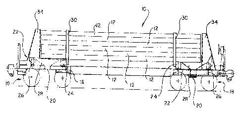
[00Z7] A railcar 10 according to the present invention is shown in Figs. 1-8
with the
railcar 10 being a 100-125 ton capacity steel flat car for hauling steel slabs
12 as shown in
Figs. 1-4 and the capacity for hauling steel coils 14 as shown in Figs. 5-8.
The railcar 10
design allows steel slabs I2 of various sizes and weights to be hauled
efficiently by placing
the slabs 12 longitudinally on the railcar 10 as shown in Figs. 1-4.
[0028] The railcar 10 includes an underframe having a conventional center sill
16
supported on a cogventional pair of spaced trucks 18 through bolsters 20.
Above each truck
18 is a raised platform 22. The raised platform 22 includes a slab supporting
fr$me rr~ember
24, an outer frame member 26, and plates extending at an angle from the frame
members 24
and 26 to form a trough 28 above the holster 20. As shown in Figs. 1-4, the
slabs 12 are
supported on the frame members 24.
[0029] The slabs 12 are captive by side stanchions 30 restricting the slabs
from lateral
movement. The side stanchions 30 are attached to the platform 22 and include
slab restraints
32 moveable to accommodate differing widths of slabs 12 as best shown in Fig.
4. The
railcar 70 includes end bulkheads 34 at the longitudinal ends of the railcar
10 preventing
longitudinal tz~ovement of the slabs l2. The weight of the slabs I2 is
concEntrated near the
bolsters z0 through raised mounting platforms 22.
[00301 The railcar 10 also has the capability to haul steel coils 14 in the
trough 28
oven the bolster 20 as shown in Figs. S-8. The end bulkheads 34 restrict a»d
position the steel
coils 14 as best shown in Figs. 6 and 8 allowing the coils 14 in each trough
28 to have an 8"
gap between then for ease of loading and unloading. One end of the railcar 10
has a built-in
cross over platform. The slab side stanchions 30 double as steel coil
stanchions restri,ctang
the steel coils from unwanted unloading due to coupler forces as shown in
Figs. 5-8.
[0031] The railcar 10 of the present invention provides increased hauling
capacity for
slabs 12 over prior art slab Cars with less lineal track space. The loading
and unloading of the
4
CA 02366987 2002-O1-09
railcar 10 is improved over the prior art slab railcars. The ability to
alternatively carry steel
cc~its 14 increases the flexibility of the railcar 10. Finally, the railcar 10
eari be easily
arranged to specifically suit a specific size of steel slab 12 as well as the
diameter and width
of steel coil 14:
[0032] A further slab car according to the present invention is shown in.
Figs_ 9..12
and is a 100 ton t7at railcar designed to haul steel slabs. The railcar is
designed for 2$6,000
pound gross rail load. The railcar can accommodate steel slabs between 35" to
'72" in width
and lengths up to 44'. The details of the railcars shown in Figs. 1-12 were
previously
described in United States Provisional Patent Application Serial N'o.
60/260,443, filed
January 9, 2001 entitled "Slab and Coil Railcar", which is incorporated herein
by reference.
(0033) rt will be apparent to those of ordinary skill in the atk that many
changes may
be made to the present invention without departing from the spirit and scope
thereof The
scope of the present invention, is tot intended to be restricted by the
specific embodiments
described, The detailed embodiments are intended to be illustrative and not
re$trictive of the
present invention.