Note: Descriptions are shown in the official language in which they were submitted.
CA 02367551 2001-09-12
WO 00/54870 PCT/CA00/00293
TITLE: Transfer of Shear-thinning slurries
TECHNICAL FIELD
This invention relates to high solids concentration slurries showing shear-
thinning visco-plastic rheological properties and, more specifically, to a
process and apparatus which allows for improved transfer of such thick, high
solids content slurries or mud from a reservoir to a conduit or any other
transportation device.
BACKGROUND ART
A large number of industrial processes generate solids residues which
normally have to be washed and transported to disposal sites or to other
recycling processes. The most common method used in industry to
transport these solids residues is to slurry them in a carrying medium, water
being the most commonly used medium, and to pump them to the desired
destination. If the slurry is sufficiently concentrated, other means of
transfer,
such as belt conveyors, can also be used. It is important and most
desirable, from an economical point of view, to operate with slurries of the
highest solids concentration possible. This keeps the total amount of
material to be handled, and eventually to be disposed of, to a minimum.
When washing is necessary, a high solids content allows a maximum
washing efficiency in the minimum number of washing stages. Finally,
maximizing the solids content of a slurry has a favorable impact on the
environment by reducing the total amount of material at the disposal site and
reduces the risk of spillage and leakage of liquid effluents.
Achieving a high solids concentration from a dilute slurry can be done in
numerous ways, the most common ones being by means of filtration,
hydrocyclone, centrifuge, flotation, magnetic separation or gravity settler
CA 02367551 2001-09-12
WO 00/54870 PCT/CA00/00293
2
also called decanter or thickener. Each of these methods is capable of
producing, to various degrees, a slurry of sufficiently high concentration
that
the thickened slurry or resulting mud will behave as a paste or a compacted
cake. If the solids concentration achieved is very high and a relatively dry
cake is formed, conventional dry transportation systems, such as belt or
screw conveyors can be used. This is the case, for example, when a high
efficiency vacuum filter or a pressure filter, such as a plate and frame type
filter, is used. The high capital, operating and maintenance cost of these
filters constitute, on the other hand, a major drawback.
The introduction of synthetic flocculants for the improvement of the
pertormance of settlers/thickeners (Chandler, US patent no. 4,040,954) and
the development of high efficiency thickeners, such as the ones described
by Bagatto et al. (US patents nos. 4,830,507 and 5,080,803) and by Farmery
et al. (US patent 5,718,510) have led to a generation of equipment capable
of producing, directly in a gravity thickener, very high solids content
slurries
or muds which exhibit paste-like behavior.
These new settlers are limited, however, in performance by the need to
maintain an underflow solids concentration which is low enough to ensure
evacuation of the mud or thick slurry from the equipment. This undertlow
solids concentration is normally continuously monitored in order to avoid
situations which would result in a severe blockage and, in many instances,
the necessity to empty the reservoir by external means.
The use of positive displacement pumps to transport the material away from
the thickening equipment to an appropriate disposal site can also be a
limitation to the maximum solids concentration which can be tolerated in use.
Although such pumps have, in principle, the capacity to transport very high
solids slurries from the pressure side of the pump, the mud must be
CA 02367551 2001-09-12
WO 00/54870 PCT/CA00/00293
3
sufficiently fluid to be introduced continuously into the pump on the suction
side.
Khan et al. (US patents nos. 5,188,739 and 5,188,740) have described a
process by which a sanitary sewage sludge mixed with carbonaceous
material is fed at a relatively high solids concentration into a reactor. This
is
achieved, as Khan et al. describe it in their patents, by the action of a pump
which reduces the viscosity of the sludge by its shearing effect. In the Khan
et al. patents, the material is fed directly from a centrifuge to a pump and
is
sufficiently fluid to be evacuated from the thickening equipment. Khan et
al.'s objective is to have a material fluid enough to enter into a subsequent
reactor. However, the Khan patents do not address the problem of getting
the slurry into the pump in the first place.
In summary, therefore, the difficulty of handling and transferring high
viscosity slurries has limited the attempts to maximize the solids contents of
such slurries, and has therefore limited the advantages that the formation of
such slurries could offer.
DISCLOSURE OF THE INVENTION
An object of the invention is to make it possible to transfer high viscosity
slurries from containers with reliability and consistency.
Another object of the invention is to facilitate transfer of high viscosity
slurries, thus allowing thickening equipment to be used more efficiently and
effectively.
Yet another object of the present invention, at least in its preferred forms,
is
to provide a method of, and apparatus for, moving slurries out of reservoirs
or equipment such as, but not exclusively, deep thickeners and high
CA 02367551 2001-09-12
WO 00/54870 PCT/CA00/00293
4
efficiency settlers, so that such slurries may be transferred from the
equipment in which they are formed or held to destinations where they may
be used, treated or discarded. Such movement may be possible when the
slurries are very thick, and have paste-like consistency exhibiting shear
thinning visco-plastic rheological properties (non-Newtonian fluids).
According to one aspect of the invention, there is provided a method of
removing a slurry having shear-thinning visco-plastic properties from a
reservoir holding a body of said slurry, wherein slurry is withdrawn from the
body through an outlet provided in the reservoir. The invention provides that
a submerged region of shear-thinned slurry of reduced viscosity is created in
said body of slurry, and a portion of the slurry of reduced viscosity is
permanently removed from said reservoir.
More preferably, the invention relates to a method of removing a slurry
having shear-thinning visco-plastic properties from a reservoir holding a
body of the slurry, the slurry having a viscosity so high that direct
withdrawal
of a flow of the slurry from the reservoir is difficult, impractical or
impossible,
the method comprising: creating a submerged region of shear-thinned slurry
of reduced viscosity in the body of slurry for entraining adjacent slurry of
the
high viscosity; and removing from the reservoir a portion of the slurry of
reduced viscosity containing entrained slurry of high viscosity. The region of
shear-thinned slurry is preferably created by withdrawing slurry temporarily
from the submerged region via an outlet to form a flow of withdrawn slurry,
subjecting the withdrawn slurry to shear force to produce a flow of shear-
thinned slurry of reduced viscosity, and returning the shear-thinned slurry of
reduced viscosity to the submerged region of the body via an inlet spaced
from the outlet, thereby creating a flow of slurry between the inlet and the
outlet. This withdrawal, shear application and return is preferably carried
out continuously, at least during the period when slurry is to be transferred
from the reservoir.
CA 02367551 2001-09-12
WO 00/54870 PCT/CA00/00293
According to another aspect of the invention, there is provided apparatus for
holding and delivering a slurry having shear-thinning visco-plastic
rheological properties, said apparatus having a reservoir for holding a body
5 of said slurry, a slurry outlet and a slurry remover for removing from the
reservoir a portion of said slurry; characterized in that the apparatus
further
includes a shear generator for creating a submerged region of slurry of
reduced viscosity in said body adjacent to the outlet.
The apparatus preferably comprises a first conduit having an inlet in the
reservoir for withdrawing slurry from the submerged region, shear
generating means communicating with the first conduit for subjecting
withdrawn slurry from the first conduit to shear, a second conduit
communicating with the shear generating means, having an outlet in the
reservoir, for returning shear-thinned slurry of reduced viscosity from the
shear generating means to the submerged region of the body, the inlet and
the outlet being spaced from each other in the region, thereby creating a
stream of slurry between the inlet and the outlet.
The invention may be used with any slurry having the required shear-
thinning visco-plastic rheological properties. Slurries derived from all
common mineral tailings (e.g. red mud from bauxite, tailings from zinc,
copper, gold, iron ore and platinum extractions, and residues from tar sands,
calcium tailings, etc.) have such properties, so the invention is of
particular
application to such slurries. The invention is also particularly suited for
use
on a continuous, semi-batch or batch basis (but most especially a
continuous basis) in combination With (e.g. is the same vessel as) slurry
thickeners or concentrators of the type discussed above.
By the term "shear-thinning visco-plastic rheological properties" used herein
to describe a slurry, we mean a thixotropic slurry having a viscosity that is
CA 02367551 2004-02-16
6
reduced when the slurry is subjected to mechanical shear compared to the
viscosity when the slurry is formed and remains undisturbed. The slurries with
which the invention is used are generally of such high solids content that
they
have the properties of a paste that is difficult or impractical to remove from
a
reservoir by conventional methods. Slurries having yield stress values up to
500 Pa or even more, normally 350 or 400 to 500 Pa are suitable for the
application of the present invention. Basically, the invention relates to any
slurry of the above kind that can be made to flow suitably for removal from a
reservoir under suction when subjected to shear. Shear thinning to a yield
stress in the range of 50 to less than 500, or 50 to less than 400, or even 50
to
less than 350 is preferred.
By the term "shear" we mean a force applied to the slurry that causes mixing
or turbulence sufficient to reduce the apparent viscosity of a shear-thinning
slurry. Shear varies in absolute terms according to various factors, including
the apparent viscosity of the mixture. It is more meaningful, therefore, to
use
the property "yield stress" to define the force required to mix the slurry.
Yield
stress is the minimum force required to initiate the movement or displacement
of a given slurry from the state of rest. The invention may require the
application of fairly high yield stress, e.g. in the range of 50 to 1,000 Pa.
The invention is based on the discovery that by creating a region, flow or
stream of slurry of reduced apparent viscosity within a submerged region of a
slurry of high apparent viscosity held in a reservoir, the high shear slurry
can
be entrained within the flow of slurry of reduced viscosity, and thereby be
caused to flow and to be removed from the reservoir. Slurry of high viscosity
may then move downwards to replace the slurry thus removed, and so a
constant slurry transfer from the reservoir may be achieved. The flow or
stream of low viscosity slurry may be created by re-circulating a shear-
thinning
slurry (frequently referred to hereinafter by the term of art "mud") through a
high-shear device, such as a pump, so that the apparent viscosity
CA 02367551 2001-09-12
WO 00/54870 PCT/CA00/00293
7
of the mud is greatly reduced, and this "remolded" mud can then act as a
carrier for conveying unsheared (unremolded) higher viscosity mud to the
high shear device or permanently out of the apparatus.
In this preferred form of the invention, the pump or other high shear device
is believed to operate by breaking bonds formed between the solids
particles of the mud, including the network formed by the flocculating agent
and possibly the polymer itself (normally present in such muds if produced
by slurry thickeners), which contributes to the lowering of the viscosity and
the yield stress of the system. The breaking of the bonds may have the
effect of releasing bound water, and the released water may act as a diluent
or lubricant that reduces the apparent viscosity of the mud. The remolded
lower viscosity mud, which is then re-circulated through a region of the
reservoir, mixes with higher viscosity mud in its immediate vicinity and
entrains it, e.g. by dissolving the higher viscosity mud or by physically
entraining parts of it. The pressure exerted by the column of mud above the
mixing region pushes material of higher viscosity down, filling the void
created by the mud swept out of the reservoir by the re-circulating low
viscosity mud which acts as a carrier. In this way, a continuous, downward
movement of otherwise high viscosity, quasi-static mud, is established in the
body or bed of mud. The amount of mud moving down in the reservoir is
equivalent to the amount of mud which is withdrawn from the reservoir, e.g.
via a branch conduit communicating with one of the mud recirculation
conduits or exiting a side of the reservoir near the region containing the
remolded mud.
In an especially preferred form, the invention involves providing an outlet
(hereinafter referred to as a suction point) situated on the reservoir (on the
tank wall or actually within the tank) in a region where the slurry is
approximately at the desired consistency (usually at the bottom end of the
reservoir), and providing a conduit (referred to as the suction conduit) of
CA 02367551 2001-09-12
WO 00/54870 PCT/CA00/00293
relatively short length (e.g. 30 meters or less) to connect this suction point
to
the suction port of a pump (or other high shear generating device), and
providing another (similarly short) conduit (referred to as the discharge
conduit) which connects the discharge port of the pump to another point on
the reservoir (called the discharge point), this discharge point being located
preferably at a short distance (e.g. between 0.2 and about 10 meters) from
the suction point. The pump keeps in re-circulation a less viscous, remolded
mud. A branch conduit is preferably provided communicating with either the
suction conduit or the discharge conduit to transfer part of the remolded mud
either to a transfer pump, or to any other transportation device such as a
belt or a screw conveyor. The branch conduit can alternatively be located
on a wall of the reservoir (or within the reservoir) in the vicinity of the
remolded mud. Alternatively, the recirculation pump may also serve as the
transfer pump.
In another preferred aspect of the present invention, in an arrangement
similar to the one described above, a low shear stirrer of any form or shape
may be incorporated into the reservoir to further reduce the viscosity of the
mud and further break the solids bonds and flocculated network in the
vicinity of the path of the re-circulating mud, i.e. in the region located
between the suction point and the discharge point. Preferably, this low
shear stirrer is a slow-moving mechanical device, such as, for example, a
rake or any other device to introduce additional shear and assist in moving
the thick largely unsheared slurry towards and through the suction point in
the reservoir. Incidentally, in the case of a rotational device, the term "low
shear" preferably means a device having a rotational speed of about 0.01 to
5 rpm.
In the case where a low shear stirrer is provided, a convenient method of
installation is to have a central support to which stirring elements are
connected.
CA 02367551 2001-09-12
WO 00/54870 PCT/CA00/00293
9
A preferred location to install the suction and discharge points is at the
bottom section of a reservoir, such as a thickener or a settler. They may
also be installed at the bottom section of an hydrocyclone or other
equipment of similar geometry.
The power requirement of the re-circulation device is a function of the
equivalent suction and discharge pipe dimension, the mass flow, the
apparent viscosity of the slurry, and the efficiency of the pump or other
shearing device. In practice, there is a maximum distance between the
suction and discharge points in the tank that should preferably not be
exceeded for efficient operation. This maximum distance is function of the
apparent viscosity of the mud recirculating between the two points. The
maximum distance is dictated by the efficiency of transportation of the low
viscosity mud between these two points. This maximum efficient distance is
normally in the order of 10 meters. On the other hand, if this distance is too
short, the thick mud above may have a tendency to create a bridge over the
space between the two points and block the downward movement of
unremolded mud. Distances as small as 0.2 meters have been found
effective, and it has been found that the suction and the discharge points
may be placed at any angle of each other.
The ratio of slurry re-circulated over the net amount of mud evacuated may
vary widely, e.g. from 0.25 to 10:1 depending on the apparent viscosity of
the mud after shearing. The higher the final apparent viscosity of the
remolded mud, the higher this ratio may be.
When the present invention involves recirculation of slurry and is used in
connection with a settling device, e.g. a thickener or clarifier or other
gravitational settling device, steps may be taken to create a region of shear-
thinned slurry at a lower portion of the device from the very start of the
CA 02367551 2001-09-12
WO 00/54870 PCT/CA00/00293
settling operation before the viscosity of the slurry becomes unduly high as a
result of gravitation settling. In this way, the necessary recirculation can
be
started when the viscosity of the slurry is fairly low and, once established,
the recirculation remains effective and operable even when the viscosity of
5 the surrounding slurry becomes very high. If this is not done, it may be
difficult to commence the required recirculation, especially when the
viscosity of the slurry has exceeded about 500 Pa. However, if the
recirculation can be commenced, even if the recirculation flow is initially
low,
the required region of reduced viscosity will eventually be formed and the
10 invention operated.
BRIEF DESCRIPTION OF THE DRAWINGS
Figure 1 is a cross-section of a reservoir containing high viscosity mud, and
a schematic view of one form of the re-circulation system of the present
invention.
Figure 2 is a cross-section of an inverted conical bottom portion of a
reservoir containing high viscosity mud, equipped with a low shear stirrer,
and includes a schematic view of the re-circulation system.
Figure 3 is a cross-section of a reservoir having a conical shape in one of
its
sections and having a cylindrical portion in its bottom section, containing
high viscosity mud, equipped with a low shear stirrer, and includes a
schematic view of the re-circulation system
BEST MODES FOR CARRYING OUT THE INVENTION
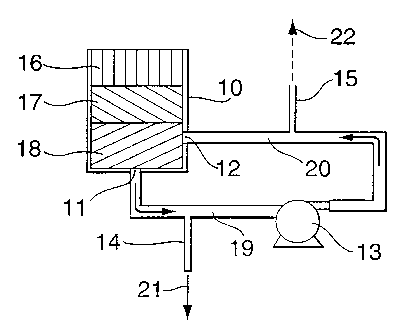
Figure 1 shows a cross section of a portion of a reservoir 10 containing
various layers of mud 16, 17 and 18 and having two openings 11 and 12 in a
bottom region of the reservoir, one opening 11 being a suction point forming
CA 02367551 2001-09-12
WO 00/54870 PCT/CA00/00293
11
a mud (slurry) outlet and the other opening 12 being a discharge point
forming a mud inlet. The mud 18 located in a submerged region
(submerged below other mud 17, 18 in the reservoir) between the two points
11 and 12 is re-circulated by a pump 13 via a suction conduit 19 and a
discharge conduit 20, as withdrawn mud of reduced apparent viscosity
(created by the high shear effect of the pump 13). This mud of reduced
apparent viscosity forms a flow moving through the body of mud from the
discharge point 12 to the suction point 11, and this flow creates a
submerged region of reduced viscosity. As the flow of mud in the region 18
moves generally from the inlet to the outlet, it mixes with adjacent high
apparent viscosity unsheared mud 17 located in its immediate vicinity. A
mixing zone is therefore created within the body of mud that may become
more extensive in volume as mud continues to be recirculated. The exact
nature of the entrainment of the high viscosity mud by the reduced viscosity
mud is not precisely known. It may take the form of actual dissolving of the
high viscosity mud within the reduced viscosity mud, or it may take the form
of physical embedding, or the like. In any event, the flow of reduced
viscosity mud carries away some of the mud of high viscosity while still
maintaining pumpable fluidity.
A portion of the high viscosity mud 17 is thus entrained with the remolded
mud 18, and will be transferred out of the reservoir 10 together with the
entraining mud of reduced apparent viscosity. Some of the mud of low
apparent viscosity entraining mud of high apparent viscosity is transferred
out of the apparatus completely (i.e. permanently) either through a branch
pipe 14 or a branch pipe 15, as chosen by the operator, and will end up as
transferred mud 21 or 22, respectively. Alternatively, the mud transferred
permanently from the apparatus may be taken directly from the submerged
region by an outlet conduit (not shown) having an opening in a wall of the
reservoir 10 adjacent to the mud 18, or projecting fully through the wall of
the reservoir and terminating at an inlet positioned within the body of mud
CA 02367551 2001-09-12
WO 00/54870 PCT/CA00/00293
12
18. The mud may be removed in this way because of its reduced apparent
viscosity in this region. A portion of high viscosity mud 17 and 16 positioned
above the re-circulated mud is then pushed downward under the pressure
exerted by its own weight and/or by any other pressure applied (e.g.
elevated air pressure applied to the headspace of the reservoir - not
shown), to fill the void created by the mud which is evacuated. In the
absence of applied pressure, the height of the column of high viscosity
mud 17, 16 above the submerged recirculation zone should preferably be
sufficient to achieve an efficient downward motion of this mud to replace
mud transferred permanently from the apparatus. This height varies from
mud to mud, particularly if the high viscosity changes from mud to mud, and
can be determined by simple trial and experiment. In general, however, the
region 18 of low apparent viscosity (between the mud inlet and outlet)
should preferably be submerged beneath the upper surface of the mud of
high apparent viscosity by a minimum distance of about 0.3 m, and more
preferably at least 1 m, in order to ensure effective entrainment of the high
viscosity mud within the mud of reduced apparent viscosity over a prolonged
period of time.
The apparatus may be operated continuously, with the amount of mud
withdrawn permanently from the reservoir equaling the amount of mud
introduced into the reservoir. The ratio of mud permanently removed to that
recirculated through the reservoir depends on the respective diameters of
the various conduits, and to some extent on the speed of recirculation
produced by the pump 13. A variable speed pump may be employed, in
order to provide a degree of control over this ratio, particularly when muds
of
different kinds or viscosities are to be used in the apparatus.
When the apparatus forms part of a mud thickener, the recirculation can be
started when thickening of the mud first commences. In this case, the first
mud introduced into the thickener will be quite dilute and will flow easily
CA 02367551 2001-09-12
WO 00/54870 PCT/CA00/00293
13
through the conduits and pump. The mud will then gradually thicken, but will
be moved continuously through the circuit since the shear-thinning effect will
reduce the apparent viscosity of the mud being recirculated. If the operation
has to be stopped and restarted, there is no problem because the mud in the
conduits and pump has a toothpaste-like consistency and does not settle.
Upon pump startup, the paste is squeezed through the conduits and
recirculation commences without difficulty. There is no need to purge the
pump and conduits.
Figure 2 shows a cross section of a portion of a reservoir 25 containing
various layers of mud 16', 17 and 18 and having two openings, one being a
suction point 27 and the other one being a discharge point 28 and equipped
with a low shear stirrer 26. The system essentially operates in the same
manner as the one described in Figure 1 with the added feature of the low
shear stirrer which further reduces the viscosity of the mud in the region
located between the suction point and the discharge point.
In reality, in both Figures 1 and 2, the mud zones labeled 16, 17 and 18
need not be physically sharply defined zones as they are shown in the
drawings. In particular, the layer 18 may not extend over the entire lower
surtace of the reservior and instead may form a small localized volume
within the lower layer of mud.
Typically the slurry corresponding to the layer 16 in the drawings can have a
yield stress of the order of up to 500 Pa, although slurries of higher yield
stress may be treated in some cases. The yield stress is the minimum
amount of energy or stress required to initiate the displacement of a system,
such as a slurry, which exhibits non-Newtonian viscosity behavior.
The re-circulation pump 13 provides mechanical shearing of the mud and
hence modifies the physical properties of the paste-like slurry by decreasing
CA 02367551 2001-09-12
WO 00/54870 PCT/CA00/00293
14
its apparent viscosity. In the case of concentrating equipment such as
thickeners and even hydrocyclones using synthetic flocculants, the pump
also reduces the negative effect of these flocculants on the slurry viscosity
by partially or completely destroying the long polymer chains and breaking
down the flocs. Although any type of pump supplying sufficiently high shear
is adequate, a centrifugal pump has been found to be especially capable of
providing the shear required to achieve the remolding of the mud that acts
as the carrier.
Figure 3 shows a cross section of a portion of a reservoir 125 containing
various layers of mud 116, 117 and 118 and having two openings, one being
a suction point 111 (mud outlet) and the other one being a discharge point
112 (mud inlet) and is equipped with a low shear stirrer 126. This reservoir
125 differs from the one in Figure 2 in that the bottom section is a truncated
inverted cone with a cylindrical portion at its lower end. The system
essentially operates in the same manner as the one described in Figure 1
with the added presence of the low shear stirrer 126 which further reduces
the viscosity of the mud in the region located between the suction point 111
and the discharge point 112.
In reality, the mud zones labeled 116, 117 and 118 need not be physically
sharply defined zones, as already noted for the embodiments of Figures 1
and 2.
EXAMPLES
Example 1
A red mud slurry, resulting from the digestion of a mixture of 25% African
and 75% Brazilian bauxite, was fed to a high capacity thickener. The solids
concentration at the underflow of the thickener reached approximately 53%
by weight and the yield stress was of the order of 400 Pa. This mud was
CA 02367551 2001-09-12
WO 00/54870 PCT/CA00/00293
difficult and impractical to remove from the base of the thickener and the
suction side of a positive displacement pump located a few meters away
could not be adequately fed. By the introduction of a re-circulation system
as shown in Figure 2, the yield stress measured in the re-circulation loop
5 was reduced to 100-120 Pa and the material could be continuously
withdrawn from the thickener. The positive displacement pump fed with this
remolded mud operated without difficulty. All yield stress measurements
were carried out by rotary viscometry.
10 Example 2
A thickener vessel used to settle red mud of a composition similar to the one
described in Example 1 above was limited to an undertlow concentration of
38 to 40% solids for consistent operation and to avoid frequent blockages of
15 the outlet of the thickener. A recirculation system was installed on the
vessel and the unit was able to operate without interruption at concentration
of the order of 52 to 55% solids.
Example 3
In a cylindrical vessel having an internal diameter of 7.62 cm, the bottom
section of which was coupled to a recirculating pump and a high shear
device as illustrated in US patent 5,616,831 was filled with a slurry of red
mud which after settling reached a solids concentration of 55% solids. The
yield stress measured for this slurry after settling was 485 Pa. When the
pump was turned on, the mud could not be taken out of the cylinder through
the pipe connecting to the pump.
The test was repeated again with fresh slurry of the same initial
concentration but this time, as the mud was let to settle, the underflow flow
pump and the in-line agitator were started and the slurry was re-injected at
CA 02367551 2001-09-12
WO 00/54870 PCT/CA00/00293
16
the base of the cylinder containing the slurry. The solids after few hours of
settling achieved a concentration 54.7% and the yield stress measured on
this remolded slurry was 48 Pa. The mud contained in the cylinder was then
completely removed through a branched pipe attached to the conduit
recirculating the mud back to the base of the cylinder
Although the above Examples have been carried out on red mud, which is
the residue of the digestion of bauxite, the same basic principle has been
applied to other residues such as copper and various calcium salts with
similar results. Although the percentage solids in the slurry will vary with
the
nature of the mud, the method of this invention will greatly improve the
transfer of virtually any thick slurry out of a reservoir when the slurry has
a
shear thinning visco-plastic behavior and, preferably, the initial yield
stress
of the slurry is not above about 500 Pa. This is the case for mining residues
such as zinc, gold, iron ore or platinum tailings and tar sands residues to
name a few that have been tested for their rheological properties.
Example 4
A copper tailing slurry was fed to a high capacity deep thickener. The solids
concentration measured was approximately 68% solids by weight and yield
stress was such that the tailing slurry would not flow by gravity from the
thickener to a floor trench. The yield stress was measured in the field using
a modified version of the cement slump test using a cylinder 100 mm in
diameter by 200 mm in height. In a slump test, the larger the diameter
measured, the less viscous the material. In terms of yield stress this would
translate into a lower yield stress for higher slump value. The measured
slump from the thickener was 130 mm. By using a recirculation system such
as the one illustrated in Figure 2, the "slump" was reduced to 165 mm and
the slurry could be discharged through a controlled valve into the floor
trench and to a disposal site nearby.