Language selection

Search

Patent 2368170 Summary

Third-party information liability

Some of the information on this Web page has been provided by external sources. The Government of Canada is not responsible for the accuracy, reliability or currency of the information supplied by external sources. Users wishing to rely upon this information should consult directly with the source of the information. Content provided by external sources is not subject to official languages, privacy and accessibility requirements.

Claims and Abstract availability

Any discrepancies in the text and image of the Claims and Abstract are due to differing posting times. Text of the Claims and Abstract are posted:

  • At the time the application is open to public inspection;
  • At the time of issue of the patent (grant).
(12) Patent Application: (11) CA 2368170
(54) English Title: ADJUSTING DEVICE
(54) French Title: DISPOSITIF DE REGLAGE
Status: Deemed Abandoned and Beyond the Period of Reinstatement - Pending Response to Notice of Disregarded Communication
Bibliographic Data
(51) International Patent Classification (IPC):
  • B60N 2/90 (2018.01)
  • F16D 41/10 (2006.01)
  • F16D 41/20 (2006.01)
  • F16D 43/02 (2006.01)
  • G05G 5/12 (2006.01)
(72) Inventors :
  • KLINGER, KNUD (Austria)
(73) Owners :
  • SCHUKRA-GERATEBAU AG
(71) Applicants :
  • SCHUKRA-GERATEBAU AG (Austria)
(74) Agent: RICHES, MCKENZIE & HERBERT LLP
(74) Associate agent:
(45) Issued:
(86) PCT Filing Date: 2000-04-03
(87) Open to Public Inspection: 2000-10-12
Examination requested: 2002-04-04
Availability of licence: N/A
Dedicated to the Public: N/A
(25) Language of filing: English

Patent Cooperation Treaty (PCT): Yes
(86) PCT Filing Number: PCT/EP2000/002956
(87) International Publication Number: WO 2000059753
(85) National Entry: 2001-09-28

(30) Application Priority Data:
Application No. Country/Territory Date
199 15 054.0 (Germany) 1999-04-01

Abstracts

English Abstract


The invention relates to an adjusting device for an adjusting element (2)
which is mounted on an axle (1) and by means of a drive mechanism (3) can be
freely turned in both directions of rotation and blocked in each adjusted
position. The device comprises two jaws (8, 8') which by means of the drive
mechanism can together be moved in a housing (7) and at at least one end (15,
15') are each in zero-play contact with an arm (14, 14') of a scissors-type
system (12). The counter-arms (11, 11') of the scissors-type system are in
zero-play contact with a driven element (10) which is rotationally mounted and
connected to the adjusting element.


French Abstract

Dispositif de réglage pour un élément de réglage (2), placé sur un axe (1), qui peut être tourné à volonté dans les deux sens de rotation à l'aide d'un élément de commande (3) et qui peut être bloqué dans chaque position de réglage. Ledit dispositif possède deux mâchoires (8, 8') mobiles ensemble dans un boîtier (7) sous l'effet de l'élément de commande. Lesdites mâchoires sont en contact serré au niveau d'au moins une extrémité (15, 15') avec une branche (14, 14') d'un élément ciseaux (12), les contre-branches (11, 11') de l'élément ciseaux se trouvant en contact serré avec un élément entraîné (10) monté rotatif et relié à l'élément de réglage.

Claims

Note: Claims are shown in the official language in which they were submitted.

-7-
claims
1. Adjusting device for an adjusting element (2)
which is arranged on a shaft (1), can be adjusted
as desired in both directions of rotation by means
of a drive (3) and can be locked in any set
position, characterized in that the device has two
jaws (8, 8') which can be moved together in a
housing (7) by means of the drive (3) and, at at
least one end (15, 15'), are each in zero-play
contact with an arm (14, 14') of a scissors-type
arrangement (12), the opposing arms (11, 11') of
the scissors-type arrangement (12) being in zero-
play contact with an output drive element (10)
which is rotatably mounted and connected to the
adjusting element (2).
2. Adjusting device according to Claim 1,
characterized in that the jaws (8, 8') are
supported on one side on a bearing (9) in the
housing (7).
3. Adjusting device according to Claim 1 or 2,
characterized in that between the arms (14, 14')
of the scissors-type arrangement (12) that make
contact with the jaws (8, 8') there is arranged a
spring (16) which presses the arms (14, 14')
against the jaws (8, 8') under prestress.
4. Adjusting device according to one of Claims 1 to
3, characterized in that the jaws (8, 8') are
connected to a lever (17, 17', 17'') in an
articulated manner.
5. Adjusting device according to one of Claims 1 to
4, characterized in that a driver (5) that is
permanently connected to the drive engages in the
jaws (8, 8') with its projections (6, 6').

-8-
6. Adjusting device according to one of Claims 1 to
5, characterized in that the jaws (8, 8') have a
different length resting on the circumference of
the housing and therefore the scissors-type
arrangement (12) has arms (14, 14') of different
lengths in contact with the respective jaws (8,
8', respectively).
7. Adjusting device according to one of Claims 1 to
6, characterized in that the scissors-type
arrangement (12) consists of a flexurally rigid
material.
8. Adjusting device according to one of Claims 1 to
7, characterized in that the scissors-type
arrangement (12) is arranged on a freely rotatable
plate (18).
9. Adjusting device according to Claim 8,
characterized in that the plate (18) permits a
different positional arrangement of the axes of
rotation of the scissors-type arrangement (12).
10. Adjusting device according to Claim 8 or 9,
characterized in that one opposing arm (11') is
fixedly fastened to the plate (18), and one
opposing arm (11) is movably fastened to the plate
(18).
.
11. Adjusting device according to one of Claims 1 to
10, characterized in that the output drive element
(10) has rounded-off edges.
12. Adjusting device according to one of Claims 1 to
11, characterized in that the output drive element
(10) is eccentrically mounted.
13. Adjusting device according to one of Claims 1 to
12, characterized in that at one end, at least one

-9-
jaw (8, 8') is angled away from the wall of the
housing (7).
14. Adjusting device according to one of Claims 1 to
13, characterized in that the pivot (13) of the
scissors-type arrangement (12) is arranged at any
desired height between the drive element (10) and
the ends (15, 15') of the jaws (8, 8').
15. Adjusting device according to one of Claims 1 to
14, characterized in that the transmission of
force at the contact between the arms (14, 14') of
the scissors-type arrangement (12) and the ends
(15, 15') of the jaws (8, 8') is configured to
take place over an area, a part area or at a
point.
16. Adjusting device according to one of Claims 1 to
15, characterized in that the area or part-area
contacts between the arms (14, 14') of the
scissors-type arrangement (12) and the ends (15,
15') of the jaws (8, 8') is designed at any
desired angle to the radius of the housing (7).
17. Adjusting device according to Claim 4,
characterized in that the lever (17') is rotatably
mounted in the region of the contact area (9) of
the jaws (8, 8') with each other and is connected
with play to the jaws (8, 8').
18. Adjusting device according to Claim 4,
characterized in that the lever (17'') is
rotatably arranged on the shaft (1) and is
connected with play to the jaws (8, 8').

Description

Note: Descriptions are shown in the official language in which they were submitted.


CA 02368170 2001-09-28
Adjusting device
The invention relates to an adjusting device for an
adjusting element which is arranged on a sh<~ft, can be
adjusted as desired in both directions of rotation by
means of a drive and can be locked in any set: position.
An adjusting device of this type is disclosed by DE-Al-
195 18 424 and also by EP-Bl-0 662 403.
The known adjusting devices have an extremely
complicated construction and are therefore complicated
to mount and costly.
It is an object of the invention to improve an
adjusting device of the type mentioned at the beginning
to the effect that it has a simple construction, which
permits rapid mounting and can be produced cost-
effectively.
This object is achieved by an adjusting device having
the features of Claim 1.
Advantageous refinements of the invention are to be
taken from the subclaims.
The invention will be explained in more detail below
using exemplary embodiments and with reference to
drawings, in which:
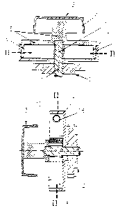
Figs la, b show cross sections through an exemplary
embodiment of an adjusting device, the
sections being located in planes shifted
through 90° with respect to each other;
Figs 2a, b show cross sections along the line II-II
from Figs la and b;

CA 02368170 2001-09-28
- 2 -
Figs 3a, b show design variants of an adjusting
device having levers;
Fig 4 shows a further design variant of an
adjusting device;
Figs 5a to f show design variants of adjusting
devices, output drive elements of
various configurations cooperating with
various scissors-type arrangements;
Figs 6a and b show design variants of the adjusting
device having a plate.
The design variant shown in Figs la, b and 2a, b of an
adjusting device has an adjusting element 2 which is
arranged on a shaft 1 and which can be adjusted as
desired in both directions of rotation by means of a
drive 3. The drive in this exemplary embodiment
comprises a handwheel 4, which is firmly connected so
as to rotate with a driver 5 having angled projections
6, 6' . The projections 6, 6' of the driver 5 engage in
two jaws 8, 8' which can be moved along the central
circumference of a circular housing 7 and, by means of
the drive 3, can be moved jointly within the housing 7,
for example into the position shown in Fig. 2b.
Instead of a manual drive, a motor drive, in particular
an electric-motor drive (not illustrated), can also be
employed.
In the exemplary embodiment illustrated in Figs 1, 2,
the jaws 8, 8' are supported on a common bearing 9,
which is designed here as a roller, that is to say as a
roller bearing, the jaws 8, 8' having appropriately
configured supporting faces.
Arranged on the shaft 1 is an output drive element 10
permanently connected to it. In the exemplary

CA 02368170 2001-09-28
- 3 -
embodiment illustrated, the output drive element 10 is
arranged coaxially with the shaft 1 and has a
rectangular cross section. The output drive element 10
is in contact with the arms 11, 11' of a scissors-type
arrangement 12, which are arranged such that they can
pivot about a common pivot 13, the corresponding
opposing arms 14, 14' associated with the arms 11, 11'
being in contact with the free ends 15, 15' of the jaws
8, a'.
The arms 11, 11', 14, 14' of the scissors-type
arrangement 12 are preferably in zero-play contact with
the ends 15 , 15 ' of the j aws 8 , 8 ' and with the output
drive element 10. It is possible for a spring 16 to be
arranged between the opposing arms 14, 14' a:nd to press
the opposing arms 14, 14' of the scissors-type
arrangement 12 against the ends 15 , 15 ' of t:he j aws 8 ,
8'.
The pivot 13 can be arranged at any desired height
between the output drive element 10 and the ends 15,
15' of the jaws 8, 8', as a result of which the lever
forces of the scissors-type arrangement 12 can be
varied.
The contact between the arms 14, 14' of the scissors-
type arrangement 12 and the ends 15, 15' of t:he jaws 8,
8' can be made over an area (see Fig. 2a), over part of
an area or at a point (not shown) . The contact area or
3 0 part contact area between the j aws 8 , 8 ' and the arms
14, 14' can be designed at any desired angle to the
radius of the housing 7. In a corresponding way, in the
case of a point-like configuration, the contact can be
provided at any desired point at the ends :15, 15' of
the jaws 8, 8'. As a result of these measures, the
friction between the jaws 8, 8' and the housing 7 can
be influenced by the introduction of different forces.

CA 02368170 2001-09-28
- 4 -
In the exemplary embodiment shown in Fig. 3a, the drive
3 comprises a lever 17 connected to the jaws 8, 8' in
an articulated manner. In the case of this linkage,
during a movement of the lever 17, the spring 16 is
initially compressed, as a result of which easier
displacement of the jaws 8, 8' and therefore of the
adjusting element 2 is possible, since in this way the
pressure of the jaws 8, 8' on the housing 7 is reduced
or virtually eliminated.
Illustrated in dashed form in Fig. 3a is a lengthened
lever 17' , which here is rotatably mounted in the area
of the bearing 9 between the jaws 8, 8'. In the case of
this lengthened lever 17', the free ends of the jaws 8,
8' are fixed to the lever 17' with play, in order to
avoid one of the jaws 8, 8' pressing on the housing 7
during any actuation of the lever 17'. Shown in Fig. 3b
is a lever 17 " , which is rotatably arranged coaxially
with or on the shaft 1. Here, too, the jaws 8, 8' are
connected to the lever 17' ' with play, no spring being
provided between the jaws 8, 8'.
In the case of the exemplary embodiment shown in Fig.
4, the arms 11, 11' of the scissors-type arrangement 12
that are connected to the output drive element 10 are
lengthened and are in contact with the other ends of
the jaws 8, 8', a bearing being dispensed with.
Fig. 5 shows different cross sections of the output
drive element 10. In addition to a rectangular cross
section, as in Fig. 2, cross sections of output drive
elements 10 having triangular, rounded-off and rounded
edges (see, in particular, Fig. 5e) are illustrated,
also the jaws 8, 8' with different lengths and also
bearings 9' (for example balls in a dome) resting on
the circumference of the housing 7 (see, in particular,
Figs 5a and 5f). The different lengths of jaws 8, 8'
and arms 11, 11' and opposing arms 14, 14' result in
different lever arms and therefore different force

CA 02368170 2001-09-28
- 5 -
transmission paths, by which means the frictional force
between the housing 7 and the jaws 8, 8' can be
influenced. The rounded designs according to Figs 5d
and 5e allow the transmission paths to be configured
from soft to hard, it also being possible for the
respective contact areas between the output drive
element 10 and the arms 11, 11' to be varied as
desired. Fig. 5f shows a design variant in which the
force relationships with respect to the points of
action A and B of the output drive element 10, as it is
rotated in the direction of the arrow, are
approximately equal on the arms 11, 11' and on the jaws
8, 8' via the opposing arms 14, 14'.
Further possible modifications permit the exemplary
embodiments according to Figs 6a and b, which have a
plate 18 which can be rotated freely with respect to
the output drive element 10. The plate 18 shown in Fig.
6a permits a different definition of the respectively
desired axes of rotation of the scissors-type
arrangement 12 which, as shown there, do not have to
coincide either.
Fig. 6b shows a variant having a plate 18', one arm 11'
being firmly connected to the plate 18' which, as
illustrated, can also be arranged eccentri,~ally with
respect to the shaft 1 and which additionally makes it
possible for the pivot 13' of the scissors-type
arrangement 12, here of the arm 11, to be displaced,
for example onto a projection 19 of the plate 18'.
The eccentric mounting of the output drive element 10'
in turn results in different force relationships which
act on the jaws 8, 8' via the arms 11, 11' and the
opposing arms 14, 14'.
The adjusting devices described operate as follows:

CA 02368170 2001-09-28
- 6 -
By means of a drive 3, for example a handwheel 4 or a
lever 17 or a motor, the jaws 8, 8' can be moved in
both directions of rotation within the housing 7. The
portions of the jaws 8, 8' that make contact with the
housing 7 are wholly adapted (see, for example, Fig. 2)
or partially adapted (see, for example, F'ig. 5f) in
their shape to the interior of the housing 7, so that
there are contact areas between them. As a result of
the zero-play connection between the jaws 8, 8' of the
scissors-type arrangement 12 and the output drive
element 10, the actuating element 2 is also moved
during a drive movement, so that any desired adjustment
can be carried out. The adjusting element 2 can be a
coil, a gear wheel or any other desired element
transmitting a movement. Once the desired adjustment
has been made, a load acts on the adjusting element 2,
generally from the object to be adjusted, fo:r example a
lumbar support whose height or curvature can be
adjusted, it being possible for the load to be assisted
by the spring 16 or applied only by the spring 16. In
this way, a load is transmitted to the output drive
element 10 which, as a result of the contact between
the latter and the scissors-type arrangement 12, has
the effect that the scissor arms attempt to open and,
in so doing, exert a pressure on the jaws 8, 8', which
are supported on the opposite side and therefore
prevent any opening of the scissors-type arrangement
12, that is to say locking occurs. In addition, the
opposing arms 14, 14' press against the ends 15, 15' of
the jaws 8, 8' , so that the latter are pressed against
the wall of the housing 7 and support locking because
of the friction effected thereby.
It is preferable for at least the scissors-type
arrangement to be produced from a flexurally rigid
material, for example a preferably abrasion-resistant
metal. The same is true of the areas which make contact
with the scissors-type arrangement, which can also have
only a hard metal covering.

Representative Drawing
A single figure which represents the drawing illustrating the invention.
Administrative Status

2024-08-01:As part of the Next Generation Patents (NGP) transition, the Canadian Patents Database (CPD) now contains a more detailed Event History, which replicates the Event Log of our new back-office solution.

Please note that "Inactive:" events refers to events no longer in use in our new back-office solution.

For a clearer understanding of the status of the application/patent presented on this page, the site Disclaimer , as well as the definitions for Patent , Event History , Maintenance Fee  and Payment History  should be consulted.

Event History

Description Date
Inactive: IPC deactivated 2019-01-19
Inactive: First IPC from PCS 2018-01-27
Inactive: IPC from PCS 2018-01-27
Inactive: IPC expired 2018-01-01
Inactive: IPC from MCD 2006-03-12
Application Not Reinstated by Deadline 2004-04-05
Time Limit for Reversal Expired 2004-04-05
Amendment Received - Voluntary Amendment 2003-04-22
Deemed Abandoned - Failure to Respond to Maintenance Fee Notice 2003-04-03
Letter Sent 2002-05-30
Inactive: Acknowledgment of national entry - RFE 2002-05-29
Letter Sent 2002-05-15
Inactive: Single transfer 2002-04-10
Request for Examination Requirements Determined Compliant 2002-04-04
All Requirements for Examination Determined Compliant 2002-04-04
Request for Examination Received 2002-04-04
Inactive: Cover page published 2002-03-14
Inactive: Courtesy letter - Evidence 2002-03-12
Inactive: Notice - National entry - No RFE 2002-03-11
Inactive: Filing certificate correction 2002-03-04
Filing Requirements Determined Compliant 2002-03-04
Application Received - PCT 2002-02-15
Inactive: Correspondence - Formalities 2001-10-11
Application Published (Open to Public Inspection) 2000-10-12

Abandonment History

Abandonment Date Reason Reinstatement Date
2003-04-03

Maintenance Fee

The last payment was received on 2001-09-28

Note : If the full payment has not been received on or before the date indicated, a further fee may be required which may be one of the following

  • the reinstatement fee;
  • the late payment fee; or
  • additional fee to reverse deemed expiry.

Please refer to the CIPO Patent Fees web page to see all current fee amounts.

Fee History

Fee Type Anniversary Year Due Date Paid Date
Registration of a document 2001-09-28
Basic national fee - standard 2001-09-28
MF (application, 2nd anniv.) - standard 02 2002-04-03 2001-09-28
Request for examination - standard 2002-04-04
Owners on Record

Note: Records showing the ownership history in alphabetical order.

Current Owners on Record
SCHUKRA-GERATEBAU AG
Past Owners on Record
KNUD KLINGER
Past Owners that do not appear in the "Owners on Record" listing will appear in other documentation within the application.
Documents

To view selected files, please enter reCAPTCHA code :


To view images, click a link in the Document Description column. To download the documents, select one or more checkboxes in the first column and then click the "Download Selected in PDF format (Zip Archive)" or the "Download Selected as Single PDF" button.

List of published and non-published patent-specific documents on the CPD .

If you have any difficulty accessing content, you can call the Client Service Centre at 1-866-997-1936 or send them an e-mail at CIPO Client Service Centre.


Document
Description 
Date
(yyyy-mm-dd) 
Number of pages   Size of Image (KB) 
Representative drawing 2002-03-13 1 12
Cover Page 2002-03-14 1 42
Abstract 2001-09-28 1 17
Drawings 2001-09-28 7 189
Claims 2001-09-28 3 109
Description 2001-09-28 6 264
Notice of National Entry 2002-03-11 1 195
Acknowledgement of Request for Examination 2002-05-15 1 179
Notice of National Entry 2002-05-29 1 202
Courtesy - Certificate of registration (related document(s)) 2002-05-30 1 114
Courtesy - Abandonment Letter (Maintenance Fee) 2003-05-01 1 176
PCT 2001-09-28 15 594
Correspondence 2001-10-11 8 274
Correspondence 2002-03-11 1 30
Correspondence 2002-03-04 1 48