Note: Descriptions are shown in the official language in which they were submitted.
CA 02368555 2002-O1-18
GAS TURBINE SPhIT RING
FIELD OF THE INVENTION
The present invention relates to a gas turbine split
ring and. More specifically, this invention relates to a
.split ring which appropriately secures an interval (chip
clearance) with respect to a tip end of a moving-blade in
the operating state of a gas turbine (under high
temperatures).
BACKGROUND OF THE INVENTION
Fig. 10 shows a general section view showing a front
stage part in a gas passage part of a gas turbine . In the
drawing, to an attachment flange '31 of a combustor 30, an
outer shroud 33 and an inner shroud 34 which fix each end
of a first stage stationary blade (lc) 32 are attached, and
the first stage stationary blade 32.is circumferentially
arranged in plural about the axis of the turbine and fixed
to the cabin on the stationary side.
On the downstream side of the first stage stationary
blade 32, a first stage moving blade (ls) 35 is arranged
in plural, and the first stage moving blade 35 is fixed to
a platform 36, the platform 36 being fixed to the periphery
of a rotor disc so that the first stage moving blade 35 rotates
together with the rotor. Furthermore, in the periphery to
1
CA 02368555 2002-O1-18
which the tip end of the first stage moving blade 35 neighbors,
a split ring 42 of circular ring shape having a plural split
number is attached and fixed to the side cabin side.
On the downstream side of the first stage moving blade
35, a second stage stationary blade (2c) 37 of which each
side is fixed to an outer shroud 38 and an inner shroud 39
is circurnferentially attached in plural to the stationary
side in the same manner as the first stage stationary blade
32. Furthermore, on the downstream side of the second
stationary stage 37, a second stage moving blade (2s) 40
is attached to the rotor disc via a platform 41, and in the
periphery to which the tip end of the second stage moving
blade 40 neighbors, a split ring 43 of circular ring shape
having a plural split number is attached.
The gas turbine having such a blade arrangement is
configured by, for example, four stages, wherein high
temperature gas 50 obtained by combustion in the combustor
30 enters from the first stage stationary blade 32, expands
while flowing between each blade of the second to fourth
stages, supplies rotation power to the rotor by rotating
each of the moving blades 35, 40 or the like, and then be
discharged outside.
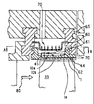
Fig. 11 is a detailed section view of the split ring
42 to which the tip end of the first stage moving blade 35
neighbors . In this drawing, a number of cooling ports 61
2
CA 02368555 2002-O1-18
are provided in an impingement plate 60 so as to penetrate
through it, and this impingement plate 60 is attached to
a heat shielding ring 65.
Also the split ring 42 is attached to the heat shielding
ring 65 by means of cabin attachment flanges formed on both
the upstream and downstream sides of main flow gas 80 which
is the high temperature gas 50. Inside the split ring 42,
a plurality of cooling passages 64 thorough which the cooling
air passes are pierced in the flow direction of the main
flow gas 80, and one opening 63 of the cooling passage 64
opens to the outer peripheral surface on the upstream side
of the split ring 42, while other opening opens to the end
surface on the downstream side.
In the above-mentioned configuration, cooling air 70
extracted from a compressor or supplied from an external
cooling air,supply source flows into a cavity 62 via the
cooling port 61 of the impingement plate 60, and the cooling
air 70 having flown into the cavity 62 comes into collision
with the split ring 42 to forcefully cools the split ring
42, and then the cooling air 70 flows into the cooling passage
64 via the opening 63 of the cavity 62 to further cool the
split ring 42 from inside, and is finally discharged into
the main flow gas 80 via the opening of the downstream side .
Fig. 12 is a perspective view of the above-described
split ring 42. As shown in the drawing, the split ring 42
3
CA 02368555 2002-O1-18
is composed of a plurality of split structure segments
divided in the circumferential direction about the axis of
the turbine, and a plurality of these split structure
segments are connected in the circumferential direction to
form the split ring 42 having a circular ring shape as a
whole. On the outside (upper side in the drawing) of the
split ring 42 is provided the impingement plate 60 which
forms the cavity 62 together with the recess portion of the
split ring 42.
The impingement plate 60 is formed with a number of
cooling ports 61, and the cooling air 70 flows into the cavity
62 via the cooling ports 61, comes into collision with the
outer peripheral surface of the split ring 42, cools the
split ring 42 from outer peripheral surface, flows into the
cooling passage 64 via the opening 63, flows through the
cooling passage 64, and is discharged into the main flow
gas 80 from the end surface, whereby the cooling air 70 cools
the split ring from inside in the course of passing through
the cooling passage 64.
As described above, the split ring of the gas turbine
is cooled by the cooling air, however, in the operating state
of the gas turbine, since the surface of the split ring is
exposed to the main flow gas 80 of extremely high temperature,
the split ring will heat expand in both the circumferential
and the axial direction.
4
CA 02368555 2002-O1-18
The interval between the tip end of the moving blade
of the gas turbine and the inner peripheral surface of the
split ring becomes small under high temperatures or under
the operating state due to the influence of centrifugal force
and heat expansion in comparison with the situation under
low temperatures or under the unoperating state, and it is
usual to determine a design value and a management value
of the tip clearance in consideration of the amount of change
of this interval. In practice, however, the inner
peripheral surface of the split ring often deforms into a
shape which is not a shape that forms a part of the cylindrical
surface because of a temperature difference between the inner
peripheral side and the outer peripheral side of the split
ring, so that there is a possibility that the rotating moving
blade and the split ring at rest interfere with each other
to cause damages of both members.
In view of the above situation, the applicant of the
present invention has proposed a split ring in which for
the purpose of suppressing the heat deformation under high
temperatures, on the outer peripheral surface between two
cabin attachment flanges in the split structure segments
constituting thesplitring,acircumferentialribextending
in the circumferential direction and an axial rib extending
in the direction parallel to the axis of the circular ring
shape are formed in plural lines to provide a rib in the
5
CA 02368555 2002-O1-18
shape of a waffle grid as a whole (Japanese Patent Application
No. 2000-62492) . According to this invention, ,the rib in
the form of a waffle grid suppresses the heat deformation,
making it possible to secure an appropriate tip clearance .
However, even by the above proposition of the present
applicant, that is, by formation of the rib in the form of
a waffle grid, it is impossible to suppress the heat
deformation of the split ring satisfactorily.
SUMMARY OF THE INVENTION
It is an object of the invention to provide a spli t
ring which makes it possible to secure a tip clearance with
respect to a tip end of a moving blade in the operating state
of a gas turbine (under high temperatures).
The gas turbine split ring according to one aspect
of the present invention is a gas turbine split ring which
is provided on a peripheral surface in a cabin at a
predetermined distance with respect to a tip end of a moving
blade, the split ring being made up of a plurality of split
structuresegmentsthatareconnectedin thecircumferential
direction to form the split ring of a circular ring shape,
eachsplitstructuresegmenthaving cabin attachmentflanges
extending in the circumferential direction on both of the
upstream and downstream sides of high temperature gas . On
an outer peripheral surface between two cabin attachment
6
CA 02368555 2002-O1-18
flanges of the split structure segment, a circumferential
rib which extends in the circumferential direction and an
axial rib which extends in the direction parallel to the
axis of the circular ring shape and has a height alley than
the circumferential rib are formed in plural lines . That
is, in this gas turbine split ring, the axial rib is formed
to be higher than the circumferential rib in the waffle grid
rib formed on the outer peripheral surface of the gas turbine
split ring.
The height of the axial rib is designed to be larger
than that of the. circumferential rib as described above on
the basis of the findings by means of simulation made by
the inventors of the present application that heat
deformationinthe axial direction contributes toreduction
of the tip clearance more largely than heat deformation in
the circumferential direction. Also from the view point
of not preventing the cooling air supplied via the cooling
ports of the impingement plate from flowing into the openings
of the cooling passages formed on the outer peripheral
surface of the split ring, the height of the circumferential
rib is suppresse d.
That is, the split ring is formed by connecting a
plurality ofsplitstructuresegmentsinthecircumferential
direction as described above, and since a clearance is formed
at the connecting portion in expectation of heat expansion
7
CA 02368555 2002-O1-18
under high temperatures, heat deformation can be absorbed
more or less at this clearance part, while on the other hand,
as for the axial direction, since two cabin attachment
flanges are attached to the cabin without leaving a clearance,
heat deformation cannot be absorbed, and the peripheral wall
part between two cabin attachment flanges protrudes to the
moving blade side to reduce the tip clearance.
In view of the above, according to the gas turbine
split ring of the present invention, by forming the axial
20 rib to be higher than the circumferential rib in the waffle
grid rib formed on the outer peripheral surface of the split
ring, the section modulus in the axial direction is made
smaller than that of the conventional case, and the amount
of heat deformation in the axial direction which contributes
to the change of the tip clearance more largely than heat
deformation in the circumferential direction, with the
result that it is possible to suppress the change of the
tip clearance due to a temperature difference compared to
the conventional case.
The gas turbine split ring according to an another
aspect of the present invention is a gas turbine split ring
which is provided on a peripheral surface in a cabin at a
predetermined distance with respect to a tip end of a moving
blade, the split ring being made up of a plurality of split
structure segments that are connected in the circumferential
8
CA 02368555 2005-O1-20
28964-49
direction to form the split ring of a circular ring shape,
each split structure segment having cabin attachment flanges
extending in the circumferential direction on both of the
upstream and downstream sides of high temperature gas. The
split ring is formed to have a shape before heat deformation
such that the inner peripheral surface of the split
structure segment and the tip end of the moving blade has a
predetermined interval in heat deformed condition in the
operating state of the gas turbine.
In the above-mentioned gas turbine split ring, the
split ring is formed into a shape in expectation of heat
deformation so that the tip clearance becomes a
predetermined clearance in the condition after heat
deformation regardless of presence/absence of the waffle
grid rib.
According to the gas turbine split ring, the shape
of the split ring before the heat deformation is formed in
expectation of heat deformation regardless of
presence/absence of the waffle grid rib, with the result
that it is possible to control the tip clearance after heat
deformation more properly.
A broad aspect of the invention provides a gas
turbine split ring which is provided at a distance with
respect to a tip end of a moving blade, the split ring
comprising a plurality of split structure segments connected
in a circumferential direction to form a circular ring
shape, each split structure segment having cabin attachment
flanges extending in the circumferential direction on both
of an upstream side and a downstream side of the split ring,
wherein on an outer peripheral surface between two cabin
attachment flanges of the split structure segment,
9
CA 02368555 2005-O1-20
28964-49
circumferential ribs extending in the circumferential
direction intersect with axial ribs extending in a direction
parallel to an axis of the circular ring shape, the axial
ribs having a height taller than the circumferential ribs.
Other objects and features of this invention will
become apparent from the following description with
reference to the accompanying drawings.
BRIEF DESCRIPTION OF THE DRAWINGS
9a
CA 02368555 2002-O1-18
Fig. 1A is a sectional view of a split ring according
to a first embodiment of the present invention, and Fig.
1B is a view taken in the direction of the arrows A-A in
Fig. 1A;
Fig. 2 is a perspective view of the split ring shown
in Fig. lA;
Fig. 3 is a view showing heat deformation of the split
ring;
Fig . 4A and Fig . 4B are views showing simulation results
of heat deformation in the axial direction and the
circumferential direction of the split ring (part 1);
Fig. 5A and Fig. 5B are views showing simulation results
of heat deformation in the axial direction and the
circumferential direction of the split ring (part 2);
Fig. 6A and Fig. 6B are views showing simulation results
of heat deformation in the axial direction and the
circumferential direction of the split ring (part 3);
Fig. 7A and Fig. 7B are views showing simulation results
of heat deformation in the axial direction and the
~ircumferential direction of the split ring (part 4);
Fig. 8 is a perspective view showing a gas turbine
split ring according to a second embodiment of the present
invention;
Fig. 9 is a view showing the shape of the inner
peripheral surface of the split ring shown in Fig. 8;
CA 02368555 2002-O1-18
Fig. 10 is a general section view showing agas passage
part of a gas turbine;
Fig. 11 is a section view of a conventional split ring
to which a first stage moving blade neighbors;
Fig. 12 is a perspective view of the conventional split
ring.
DETAILED DESCRIPTION
Embodiments of the gas turbine split ring according
to the present invention will be concretely explained with
reference to the. accompanying drawings.
Fig. 1A is a sectional view of a split ring according
to a first embodiment, and Fig. 1B is a view taken in the
direction of the arrows A-A in Fig. 1A. In Fig. l, the split
ring 1 shows one of a plurality of split structure segments
constituting a split ring of circular ring shape, the split
ring 1 being attached to the heat shielding ring 64, having
the opening 63 in the cavity 62, and being provided with
a number of cooling passages 64 opening to the end surface
on the downstream of the main flow gas 80 in the same manner
as the conventional split structure segment. Also the
impingement plate 60 is attached to the heat shielding ring
65 in the same manner as the conventional case. On both
ends on the upstream and downstream sides of the split ring
1, the cabin attachment flanges 4, 5 extending in the
11
CA 02368555 2002-O1-18
circumferential direction are provided.
On an outer peripheral surface 1b of the split ring
1 is formed a waffle grid rib 10 consisting of a
circumferential rib lob extending in the circumferential
direction and an axial rib_10a extending in the axial
direction. The height of the circumferential rib 10b is
3 mm, while the axial rib 10a is formed to be 12 mm high
and taller than the circumferential rib 10b.
Fig. 2 is a perspective view of a single split ring
1, and by connecting a plural number of split rings 1 along
the circumferential direction (shown in the drawing) so as
to neighbor to the tip end of the moving blade while leaving
an appropriate tip clearance C, the split ring 1 having a
circular ring shape as a whole is formed. The number to
be connected is determined in accordance with the size of
the split ring and the length of arrangement circle for
achieving arrangement of one circle of the circular ring
(for example, about 40 segments).
In the split ring 1 having the configuration as
described above, the cooling air 70 extracted from a
compressor as shown in Fig. 1 or supplied from an external
cooling air supply source flows into the cavity 62 via the
number of cooling ports 61 formed in the impingement plate
60, comes into collision with the outer peripheral surface
1b of the split ring 1 to impinge-cool the split ring l,
12
CA 02368555 2002-O1-18
and flows into the cooling passage 64 via the opening 63,
flows through the cooling passage 64 while cooling the
interior of the split ring l, and is finally discharged into
the main flow gas 80 via the opening of the downstream side .
As described above, though the split ring 1 is cooled
by the cooling air 70, the conventional split ring 1 heat
deforms because of a temperature difference between the inner
peripheral surface la which is directly exposed to the main
flow gas 80 which is high temperature burned gas and the
outer peripheral surface 1b which does not contact with the
main flow gas 80, and the tip clearance C with respect to
the tip end of the moving blade 35 becomes small as indicated
by the broken line in Fi'g. 3, so that the desired tip clearance
C is no longer secured and there arises a possibility that
the rotating moving blade 35 and the inner peripheral surface
1a at rest of the split ring 1 interfere with each other
and both members get damaged.
However, according to the split ring 1 of the first
embodiment, owing to the waffle grid rib 10 formed on the
outer peripheral surface 1b, heat deformation in the
circumferential direction and in the axial direction is
suppressed, so that reduction of the above-mentioned tip
clearance C is also suppressed. In addition, though the
degree of contribution to reduction in the tip clearance
C is larger in the axial deformation than in the
13
CA 02368555 2002-O1-18
circumferential deformation, in the split ring 1 which is
the first embodiment of the invention, the axial rib l0a
is formed to be higher than the circumferential rib lOb in
the waffle rigid rib 10, with the result that it is possible
to further suppress the heat deformation.
Fig. 4A to Fig. 7B show comparison results in which
heat deformed conditions of the split ring under high
temperatures are determined by simulation. Each of Fig.
4A, Fig. 5A, Fig. 6A, and Fig. 7A shows a radial displacement
along the axial direction at each point A, B, C in the
circumferential direction of Fig. 2, and each of Fig. 4B,
Fig. 5B, Fig. 6B, and Fig. 7B shows a radial displacement
along the circumferential direction at each point LE ( Leading
Edge), MID (middle), TE (Trailing Edge) in the axial
direction of Fig. 2. Moreover, Fig. 4A and Fig. 4B show
the result for the conventional split ring not having a waffle
grid rib, Fig. 5A and Fig. 5B show the result for the split
ring having a waffle grid rib of which axial rib and the
circumferential rib are 3 mm high (width of 2 mm and pitch
of 20 mm for the axial rib), and Fig. 6A to Fig. 7B show
the results for the split ring according to the first
embodiment having a waffle grid rib of which circumferential
rib is 3 mm high and axial rib is 12 mm high (width of 2
mm and pitch of 20 mm for the axial rib), and Fig. 4A to
Fig. 6B show the results at the maximum metal temperature
14
CA 02368555 2002-O1-18
of 880 °C and Fig. 7A and Fig. 7B show the result at the
maximum metal temperature of 1020 °C.
As is evident from these drawings, under the same metal
temperature, as for the split ring 1 according to the first
embodiment shown in Fig. 6A and Fig. 6B, the amount of
displacement is reduced both in the axial direction and in
the circumferential direction in comparison with the split
ring not having a waffle grid rib or the split ring having
a waffle grid rib of which ribs in the axial direction and
the circumferential direction are 3 mm high, and it was also
proved that the distribution range of the amount of
displacement along the circumferential direction at each
of the points LE, MID, TE and the distribution range of the
amount of displacement along the axial direction at each
of the points A, B, C are reduced.
Also as for the split ring 1 according to the first
embodiment under the maximum metal temperature of 1020 °C
(Fig. 7A and Fig. 7B) , it was confirmed that the amount of
displacement is smaller than those of the conventional split
ring (Fig. 4A and Fig. 4B) and the split ring having a waffle
grid rib having the same height in the axial direction and
the circumferential direction (Fig. 5A and Fig. 5B) under
the maximum metal temperature of 888 °C.
As described above, according to the gas turbine split
ring 1 of the first embodiment, the amount of heat deformation
CA 02368555 2002-O1-18
in the axial direction which largely contributes to the
change in the tip clearance C is predominantly made smaller
than that of the conventional case, so that it is possible
to efficiently suppress the change of tip clearance C due
to the temperature difference.
Fig. 8 shows the split ring 1 according to a second
embodiment. The split ring 1 is such that, in the
conventional split ring not having a waffle grid rib, the
inner peripheral surface la opposing to the tip end of the
moving blade 35 is formed into a recess shape with respect
to the moving blade 35 under normal temperatures (low
temperatures at the time of unoperating state of the gas
turbine).
As shown in Fig. 9 in detail, this recess shape is
a shape under normal temperatures (denoted by the solid bold
line in Fig. 9) that is designed in expectation of heat
deformation so that the tip clearance C between the tip end
of the moving blade 35 and the substantially center part
in the axial direction of the inner peripheral surface 1a
becomes a desired value after heat deformation (denoted by
the double dotted line in Fig. 9) in the operating state
of the gas turbine (under high temperatures) , and is a shape
such that the distance with respect to the moving blade 35
under normal temperatures decreases with distance from the
substantially center part of the inner peripheral surface
16
CA 02368555 2002-O1-18
1a to both of the upstream and downstream sides.
As explained with regard to Fig. 3, in the conventional
split ring, heat deformation occurs so that it protrudes
to the tip end side of the moving blade 35 under high
temperatures because of operation of the gas turbine, and
hence the tip clearance C at the substantially center part
in the axial direction of the inner peripheral surface 1a
becomes insufficient, however, according to the split ring
l of the second embodiment, the tip clearance C becomes a
desired optimum value after heat deformation and such
shortage will not occur.
The split ring 1 of the second embodiment is formed
into a recess shape in its entirety, however, since the
essential feature is that at least the tip clearance C between
the inner peripheral surface 1a and the tip end of the moving
blade 35 becomes a desired value after heat deformation,
only the inner peripheral surface 1a is formed into a recess
shape instead of forming the entire split ring 1 into a shape
that is bend in recess shape. Furthermore, various shapes
such as parabola and part of a circle are applicable for
the contour shape of the cross section by the surface
containing the rotation axis of the turbine in the inner
peripheral surface 1a.
Furthermore, the second embodiment may also be applied
to the split ring 1 having the above-described waffle grid
17
CA 02368555 2002-O1-18
rib 10 which is the first embodiment.
As described above, according to the gas turbine split
ring of one aspect of the present invention, in the waffle
grid rib formed on the outer peripheral surface, the axial
rib is formed to be higher than the circumferential rib so
as to increase the section modulus in the axial direction
and predominately decrease the amount of heat deformation
in the axial direction which largely contributes the change
of the tip clearance compared to the amount of heat
deformation in the circumferential direction, with the
result that it is possible to efficiently suppress the change
of the tip clearance due to a temperature difference.
Moreover, the amount of heat deformation in the axial
direction is reduced compared to the conventional case by
forming the axial rib to be higher than the circumferential
rib, while the shape of the split ring before heat deformation
is formed in expectation of heat deformation which will
nonetheless occur, with the result that it is possible to
control the tip clearance after heat deformation more
properly.
According to the gas turbine split ring of another
aspect of the present invention, the shape of the split ring
before heat deformation is formed in expectation of heat
deformation regardless of presence/absence of the waffle
grid rib, with the result that it is possible to control
18
CA 02368555 2002-O1-18
the tip clearance after heat deformation more properly.
Moreover, it is possible to control the tip clearance
after heat deformation properly even for the substantially
center part in the axial direction of the inner peripheral
surface of the split ring where heat deformation is the
maximum.
Although the invention has been described with respect
to a specific embodiment for a complete and clear disclosure,
the appended claims are not to be thus limited but are to
be construed as embodying all modifications and alternative
constructions that may occur to one skilled in the art which
fairly fall within the basic teaching herein set forth.
19