Language selection

Search

Patent 2368718 Summary

Third-party information liability

Some of the information on this Web page has been provided by external sources. The Government of Canada is not responsible for the accuracy, reliability or currency of the information supplied by external sources. Users wishing to rely upon this information should consult directly with the source of the information. Content provided by external sources is not subject to official languages, privacy and accessibility requirements.

Claims and Abstract availability

Any discrepancies in the text and image of the Claims and Abstract are due to differing posting times. Text of the Claims and Abstract are posted:

  • At the time the application is open to public inspection;
  • At the time of issue of the patent (grant).
(12) Patent: (11) CA 2368718
(54) English Title: PORTABLE ELECTRIC APPLIANCE WITH CORD HOLDER
(54) French Title: APPAREIL MENAGER ELECTRIQUE AVEC BARBOTIN DE CORDON D'ALIMENTATION
Status: Expired and beyond the Period of Reversal
Bibliographic Data
(51) International Patent Classification (IPC):
  • H05K 07/02 (2006.01)
  • B65H 75/36 (2006.01)
  • H02G 11/02 (2006.01)
(72) Inventors :
  • TSUJI, MASAO (United States of America)
  • CARBAJAL, FRANCISCO J. (United States of America)
(73) Owners :
  • HUNTER FAN COMPANY
  • HUNTER FAN COMPANY
(71) Applicants :
  • HUNTER FAN COMPANY (United States of America)
  • HUNTER FAN COMPANY (United States of America)
(74) Agent: FINLAYSON & SINGLEHURST
(74) Associate agent:
(45) Issued: 2009-03-31
(22) Filed Date: 2002-01-21
(41) Open to Public Inspection: 2002-07-22
Examination requested: 2002-05-24
Availability of licence: N/A
Dedicated to the Public: N/A
(25) Language of filing: English

Patent Cooperation Treaty (PCT): No

(30) Application Priority Data:
Application No. Country/Territory Date
09/766,527 (United States of America) 2001-01-22

Abstracts

English Abstract


A portable electric appliance (10) has a housing with
recesses (20) in which posts (25) are mounted for movement
between extended and retracted positions. The appliance power
cord is wrapped about the posts for storage in their extended
positions and held in a notch (31) of a post flange (30).


Claims

Note: Claims are shown in the official language in which they were submitted.

-6-
WHAT IS CLAIMED IS:
1. A portable electrically powered appliance having a housing and
a power cord which extends out of said housing for connection to a
source of electric power, and wherein said housing has a side
formed with two recesses and two posts with manually gripable
flanges repositionably mounted to and extending from said two side
recesses for movement inboard between a retracted position with
said flanges located inboard said side recesses and an extended
position with said flanges located outboard of said side recesses,
whereby the power cord may be wrapped about the posts for appliance
transportation and storage with the posts in their extended
positions and the posts retracted when the appliance is in use.
2. The portable electric appliance of claim 1 wherein said
flanges have a notch in which an end of said electric cord may be
held.
3. The portable electric appliance of claim 1 wherein one of said
housing recesses has a hole through which said electric cord
extends adjacent one of said posts.
4. A portable electrically powered appliance having a housing
through which a power cord extends and means for holding said power
cord f lushly aside one side wall of said housing, said means
including a post that is retractably and extendably mounted to said
housing between a retracted position wherein said entire post is
positioned inboard of said side wall and an extended position
wherein a portion of said post is positional outboard of said side
wall; and
wherein said cord holding means comprises a second post
retractably and extendably mounted to said housing spaced from the
other post.

-7-
5. A portable electrically powered appliance having a housing
through which a power cord extends and means for holding said power
cord flushly aside one side wall of said housing, said means
including a post that is retractably and extendably mounted to said
housing between a retracted position wherein said entire post is
positioned inboard of said side wall and an extended position
wherein a portion of said post is positioned outboard of said side
wall;
wherein said housing has a flat rear side formed with a recess
in which said post is mounted; and
wherein said post is formed with a flange with a notch through
which said power cord may be passed.

Description

Note: Descriptions are shown in the official language in which they were submitted.


CA 02368718 2002-04-08
-1-
PORTABLE ELECTRIC APPLIANCE WITH CORD HOLDER
TECHNICAL FIELD
This invention relates to portable, electric powered
appliances such as humidifiers, air purifiers and fans.
BACKGROUND OF THE INVENTION
Portable electric appliances commonly have a power
cord that is several feet long. The cord terminates with
a plug that may be plugged into a wall socket to access a
source of municipal power. This is done when the appliance
is ready for or actually is in use. When not in use, as
when being moved about or stowed, the power cord must be
held or otherwise it will drag during transport. During
storage it should be held or coiled for compactness and
neatness.
Heretofore portable electric appliances have been
equipped with means for holding their power cord. Vacuum
cleaners, for example, commonly have hooks or cleats
mounted to their vacuum tubes. Their power cords are
wrapped over these along the tubes when the appliance is
not in use. Other appliances have been equipped with means
for retracting and storing the cord inside the appliance

CA 02368718 2005-05-13
-2-
housing. These employ spring loaded reels and thus have
moving parts and are more expensive. Others have had racks
mounted to their housing for this purpose. Exemplary of
these are those shown in U.S. Patent Nos. 2,033,491,
3,476,331 and 6,003,804.
Most power cord holders have provided projections in
one form or another. This presents little problem when the
cord is wrapped about them. However, when the appliance is
not in use these projections not only present a hazard,
they also prevent the appliance from being placed flushly
or at least closely aside a wall. Small appliances are
commonly located on kitchen countertops where space is at
a premium. Even those larger ones that are set upon
floors, such as air purifiers, humidifiers, space heaters
and fans, are preferably located closely aside a wall.
Accordingly, it is seen that a need has long existed
for portable, electric powered appliances to be provided
with power cord holders that are readily accessible and
easy to use and yet which do not provide protrusions of
significance when not in use. It thus is to the provision
of such that th present invention is primarily directed.
SUMMARY OF THE INVENTION
In a broad aspect, the invention pertains to a
portable electrically powered appliance having a housing
through which a power cord extends and means provided for
holding the power cord flushly aside one side wall of the
housing, the means including a post that is retractably and
extendably mounted to the housing between a retracted
position wherein the entire post is positioned inboard of
the side wall, and an extended position wherein a portion
of the post is positional outboard of the side wall.
In a preferred form of the invention, a portable
electrically powered appliance has a housing, an electric
load housed within the housing, and an electric power cord
coupled with the load. The power cord extends out of the
housing for connection to a source of electric power. The

CA 02368718 2005-05-13
-2a-
housing has a generally flat side formed with two recesses
and two posts with manually gripable flanges. The posts
are repositionably mounted to the housing side recesses for
movement between a retracted position with their flanges
generally coplanar with the housing side and an extended
position with their flanges located outboard of the side.
So constructed, the electric power cord. may be wrapped

CA 02368718 2002-04-08
-3-
about the posts for appliance transportation and storage
with the posts in their extended positions and the posts
retracted when the appliance is in use so that they do not
present protrusions.
BRIEF DESCRIPTION OF THE DRAWING
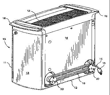
Fig. 1 is a perspective view of an air purifier that
incorporates principles of the invention in a preferred
form shown with its power cord loose.
Fig. 2 is a perspective view of the air purifier of
Fig. 1 shown with its power cord stowed.
Fig. 3 is an enlarged view, in perspective, of one of
the two cord holding posts shown in Figs. 1 and 2.
Fig. 4 is an enlarged view of a portion of the air
purifier showing one of its cord holding posts in its
retracted position while Fig. 5 shows it in its extended
position.
DETAILED DESCRIPTION
Referring now in more detail to the drawing, there is
shown an air purifier 10 that is of conventional structure
save for its inclusion of means for holding its power cord
in a stowed configuration. The air purifier has a housing
with a grill 11 on its front side that provides an air
inlet and another grill 12 on its top that provides an air
outlet. The housing also has a bottom 12, two opposite
sides 13 and a back 14. The air purifier has an unshown
blower and filter conventionally mounted inside the housing
between the air inlet and air outlet. The blower fan is
driven by an electric motor from which a power cord 15
extends. The cord terminates with a plug 16. Upon
insertion of the plug into a socket the unit may be
connected with a source of municipal power upon operation

CA 02368718 2002-04-08
-4-
of its on/off switch. The housing is formed with two hand
grips 18 for portability.
The back side 14 of the housing is generally flat
except for two recesses in its two bottom corners. The
principal walls 21 of the recesses are flat and parallel to
the back side 14. One recess wall 21 is formed with a hole
22 through which the power cord 15 extends. Each recess is
formed with a central opening through which a cylindrical
post 25 extends. The inboard end of the post is formed
with two pairs of short slits 26 that straddle a chambered
or beveled locking tab 27. The outboard end of the post is
formed with a disc-shaped or maple leaf flange 30 that has
three angularly spaced notches 31. The post may be readily
mounted to the housing rear side by inserting its end
whereupon the tabs are momentarily flexed inwardly and then
spring back to serve as stop. The posts may then be moved
between the retracted position shown in Fig. 4 and the
extended positions shown in Fig. 5. In their retracted
positions their flanges are located in the recesses 20
while in their extended positions they are located outboard
of the rear side 14.
In use the power cord plug is inserted into an
electrical receptacle like a common wall socket. The posts
are recessed as shown in Figs. 1 and 4. So configured they
do not provide protrusions that can present a hazard. This
also enables the purifier to be set closely beside a wall.
Indeed, this enables the unit, whether it be an air
purifier, or humidifier, or simply a fan, to be placed
flush against a room wall. If full flush placement is
desired a small channel is formed in the rear side that
extends from a recess 30 to a side 13 to receive the cord
15.
During storage or transportation the cord is wrapped
about the post as shown in Fig. 2. This is done by
manually pulling the two flanges 30 outwardly and then

CA 02368718 2002-04-08
-5-
wrapping the cord about the post 25. The cord is then
seated in a notch 31.
It thus is seen that a portable electric appliance is
now provided with improved means for holding its power
cord. Although the invention has been shown and described
in its preferred form, it should be understood that many
modifications, changes or additions may be made without
departure from the spirit and scope of the invention as set
forth in the following claims.

Representative Drawing
A single figure which represents the drawing illustrating the invention.
Administrative Status

2024-08-01:As part of the Next Generation Patents (NGP) transition, the Canadian Patents Database (CPD) now contains a more detailed Event History, which replicates the Event Log of our new back-office solution.

Please note that "Inactive:" events refers to events no longer in use in our new back-office solution.

For a clearer understanding of the status of the application/patent presented on this page, the site Disclaimer , as well as the definitions for Patent , Event History , Maintenance Fee  and Payment History  should be consulted.

Event History

Description Date
Time Limit for Reversal Expired 2011-01-21
Letter Sent 2010-01-21
Grant by Issuance 2009-03-31
Inactive: Cover page published 2009-03-30
Inactive: Final fee received 2008-12-31
Pre-grant 2008-12-31
Letter Sent 2008-10-15
Notice of Allowance is Issued 2008-10-15
Inactive: IPC removed 2008-10-08
Inactive: Approved for allowance (AFA) 2008-09-29
Amendment Received - Voluntary Amendment 2007-03-12
Inactive: S.30(2) Rules - Examiner requisition 2006-12-04
Amendment Received - Voluntary Amendment 2006-08-31
Inactive: S.30(2) Rules - Examiner requisition 2006-03-14
Inactive: IPC from MCD 2006-03-12
Amendment Received - Voluntary Amendment 2005-05-13
Inactive: S.30(2) Rules - Examiner requisition 2005-01-04
Letter Sent 2002-08-06
Application Published (Open to Public Inspection) 2002-07-22
Inactive: Cover page published 2002-07-21
Request for Examination Received 2002-05-24
Request for Examination Requirements Determined Compliant 2002-05-24
All Requirements for Examination Determined Compliant 2002-05-24
Inactive: Correspondence - Formalities 2002-04-08
Inactive: First IPC assigned 2002-03-14
Inactive: IPC assigned 2002-03-14
Inactive: Filing certificate - No RFE (English) 2002-02-20
Letter Sent 2002-02-20
Application Received - Regular National 2002-02-20

Abandonment History

There is no abandonment history.

Maintenance Fee

The last payment was received on 2008-12-31

Note : If the full payment has not been received on or before the date indicated, a further fee may be required which may be one of the following

  • the reinstatement fee;
  • the late payment fee; or
  • additional fee to reverse deemed expiry.

Patent fees are adjusted on the 1st of January every year. The amounts above are the current amounts if received by December 31 of the current year.
Please refer to the CIPO Patent Fees web page to see all current fee amounts.

Fee History

Fee Type Anniversary Year Due Date Paid Date
Application fee - standard 2002-01-21
Registration of a document 2002-01-21
Request for examination - standard 2002-05-24
MF (application, 2nd anniv.) - standard 02 2004-01-21 2004-01-06
MF (application, 3rd anniv.) - standard 03 2005-01-21 2005-01-14
MF (application, 4th anniv.) - standard 04 2006-01-23 2006-01-06
MF (application, 5th anniv.) - standard 05 2007-01-22 2007-01-09
MF (application, 6th anniv.) - standard 06 2008-01-21 2008-01-14
Final fee - standard 2008-12-31
MF (application, 7th anniv.) - standard 07 2009-01-21 2008-12-31
Owners on Record

Note: Records showing the ownership history in alphabetical order.

Current Owners on Record
HUNTER FAN COMPANY
HUNTER FAN COMPANY
Past Owners on Record
FRANCISCO J. CARBAJAL
MASAO TSUJI
Past Owners that do not appear in the "Owners on Record" listing will appear in other documentation within the application.
Documents

To view selected files, please enter reCAPTCHA code :


To view images, click a link in the Document Description column (Temporarily unavailable). To download the documents, select one or more checkboxes in the first column and then click the "Download Selected in PDF format (Zip Archive)" or the "Download Selected as Single PDF" button.

List of published and non-published patent-specific documents on the CPD .

If you have any difficulty accessing content, you can call the Client Service Centre at 1-866-997-1936 or send them an e-mail at CIPO Client Service Centre.

({010=All Documents, 020=As Filed, 030=As Open to Public Inspection, 040=At Issuance, 050=Examination, 060=Incoming Correspondence, 070=Miscellaneous, 080=Outgoing Correspondence, 090=Payment})


Document
Description 
Date
(yyyy-mm-dd) 
Number of pages   Size of Image (KB) 
Representative drawing 2002-03-13 1 24
Abstract 2002-04-07 1 10
Description 2002-04-07 5 179
Claims 2002-04-07 2 49
Description 2002-01-20 5 213
Abstract 2002-01-20 1 13
Drawings 2002-01-20 4 160
Claims 2002-01-20 2 58
Claims 2005-05-12 2 63
Description 2005-05-12 6 205
Claims 2006-08-30 2 54
Claims 2007-03-11 2 63
Abstract 2007-03-11 1 9
Representative drawing 2009-03-09 1 28
Courtesy - Certificate of registration (related document(s)) 2002-02-19 1 113
Filing Certificate (English) 2002-02-19 1 164
Acknowledgement of Request for Examination 2002-08-05 1 193
Reminder of maintenance fee due 2003-09-22 1 106
Commissioner's Notice - Application Found Allowable 2008-10-14 1 163
Maintenance Fee Notice 2010-03-03 1 171
Correspondence 2002-02-19 1 18
Correspondence 2008-12-30 1 34