Note: Descriptions are shown in the official language in which they were submitted.
' CA 02369254 2001-10-09
11-105956
-1-
S P E C I F I C A T I O N
DISPOSABLE WIPE-OUT SHEET AND PROCESS FOR MAKING THE SAME
TECHNICAL FIELD OF THE INVENTION
This invention relates to a disposable wipe-out sheet
suitable for wiping out dust and/or dirt from floor or wall
surfaces.
RELATED ART
Japanese Patent Application Publication No. 1997-135798
describes a disposable wipe-out sheet comprising a heat-
sealable synthetic resin base sheet and a plurality of
heat-sealable filaments bonded to the base sheet and extending
in one direction. These filaments are obtained by
deregistering or opening a tow of continuous filaments and
bonded to the base sheet by a plurality of sealing lines
extending transversely of the filaments and arranged
intermittently in the one direction. An assembly of these
filaments obtained by deregistering the two is bulky and, along
the sealing lines formed by locally pressing this assembly under
heating, a plurality of filaments are molten and solidified to
form a high density film bonded to the base sheet. Between each
CA 02369254 2001-10-09
11-105956
-2-
pair of the adjacent sealing lines, filaments form convex
bridge-like portions describing arcs which are convex upward
from the base sheet.
One of measures to improve a productivity per unit time
of the wipe-out sheet of prior art is to feed the heat-sealable
synthetic resin base sheet and the filaments at a high velocity
onto a production line so that the base sheet and filaments may
be heat-sealed together at a high velocity corresponding to said
high feeding velocity. To improve the heat-sealing velocity,
it is preferable to use synthetic resin having a relatively low
melting point for both the base sheet and the filaments and to
use the press having high temperature and pressure. However,
if a temperature of the press is adjusted to a level
substantially higher than the melting point of the synthetic
resin, both the base sheet and the filaments would be deformed
due to heat transferred from the press in their regions other
than their regions in which the sheet and the filaments. As
a result, it is difficult for the wipe-out sheet to maintain
its initial shape. Accordingly, an improvement of the
productivity by adopting a higher press temperature is
inevitably limited.
It is an object of this invention to improve the
conventional disposable wipe-out sheet so that a relatively
CA 02369254 2001-10-09
11-105956
-3-
high press temperature can be employed during a process for
making the wipe-out sheet.
DISCLOSURE OF THE INVENTION
According to the invention, there is provided a
disposable wipe-out sheet comprising a heat-sealablesynthetic
resin base sheet and a plurality of heat-sealable synthetic
resin long fibers heat-sealed with the base sheet and extending
in one direction, wherein the long fibers are heat-sealed with
the base sheet by a plurality of sealing lines arranged
intermittently in the one direction, wherein: the long fibers
comprise core-sheath type conjugated fibers wherein a melting
point of the sheath is lower than a melting point of the core
and such difference of the melting points is at least by 30 °C.
According to the invention, there is also provided a
process for making a disposable wipe-out sheet comprising a
heat-sealable synthetic resin base sheet and a plurality of
heat-sealable synthetic resin long fibers heat-sealed with the
base sheet and extending in one direction, wherein said long
fibers are heat-sealed with the base sheet by a plurality of
sealing lines arranged intermittently in the one direction,
wherein:
the long fibers comprise core-sheath type conjugated
CA 02369254 2001-10-09
11-105956
-4-
fiber wherein a melting point of the sheath is lower than a
melting point of the core and such difference of the melting
points is at least by 30 °C; a difference between a melting point
of the base sheet as measured along the sealing lines and a
melting point of the sheath in the conjugated fiber is less than
20 °C; and the base sheet and the long fibers are bonded together
at a temperature higher than the melting point of the sheath
in the conjugated fiber by 20 °C or more but lower than the
melting point of the core in the conjugated fiber.
BRIEF DESCRIPTION OF THE DRAWINGS
Fig. 1 is a perspective view showing a wipe-out sheet
according to this invention as being actually used;
Fig. 2 is a perspective view showing the wipe-out sheet
alone;
Fig. 3 is a perspective view showing an important part
of the wipe-out sheet;
Fig. 4 is a fragmentary diagram of the base sheet layer
realized in different manners (A) - (C); and
Fig. 5 is a sectional view showing the long fibers.
DESCRIPTION OF THE PREFERRED EMBODIMENTS
Details of a disposable wipe-out sheet according to this
' - CA 02369254 2001-10-09
11-105956
-5-
invention will be more fully understood from the description
given hereunder with reference to the accompanying drawings .
Fig. 1 is a perspective view showing a holder 2 with a
disposable wipe-out_ sheet 1 attached thereto. The holder 2
comprises a base plate 3 and a stick 4. The wipe-out sheet 1
placed against the lower surface of the base plate 3 has its
opposite long side edge regions 7 folded back onto the upper
surface of the base plate 3 and fastened to the upper surface
by means of clips 8 mounted on the base plate 3. Dust and/or
dirt on floor or wall surfaces may be wiped out by the wipe-out
sheet 1 attached to the holder 2 with the stick 4 gripped in
user's hands.
Fig. 2 is a perspective view showing the same wipe-out
sheet 1 as the wipe-out sheet 1 shown by Fig. 1 as partially
broken away. The wipe-out sheet 1 is herein illustrated as_have
been detached from the base plate 3 and developed with its wiper
surface facing upward. The wipe-out sheet 1 comprises a base
sheet layer 10 made of a heat-sealable synthetic resin film or
nonwoven fabric and a wiper layer 20 formed by a plurality of
heat-sealable long fibers or filaments 25 bonded to the upper
surface of the base sheet layer 10.
The base sheet layer 10 is of a rectangular shape defined
by a pair of opposite long side edge regions 11 extending
CA 02369254 2001-10-09
11-105956
-6-
parallel to each other and a pair of opposite short side edges
12 extending also parallel to each other. Band-like
reinforcing sheets 13 made of a synthetic resin film are
heat-sealed with the opposite side edge regions 11 at a
plurality of spots 15 in order to improve a tear strength of
these side edge regions 11. Referring to Fig. 2, a pair of
opposite side edge regions of the wiper layer 20 are covered
with inner edge regions 14 of the respective reinforcing sheets
13. The side edge regions 11 of the base sheet layer 10 are
formed with a plurality of slits 16 extending through these side
edge regions 11 as well as the respective reinforcing sheets
13. These slits 16 facilitate the wipe-out sheet 1 to be
attached to the holder 2 by means of the clips 8.
The wiper layer 20 comprises a plurality of long fibers
25, i.e., continuous filaments extending substantially
parallel to the side edge regions 11 of the base sheet layer
10. These long fibers 25 are heat-sealed with the base sheet
layer 10 along a plurality of sealing lines 9 intermittently
arranged to extend between the pair of opposite side edge
regions 11 substantially parallel to each other toward the
opposite short side edge regions 12 of the base sheet layer 10.
The respective long fibers 25 partially define relatively long
bridge-like portions 26A connecting each pair of the adjacent
CA 02369254 2001-10-09
11-105956
sealing lines 9 and relatively short fluffy portions 26B formed
by severing the remaining long fibers 25 between each pair of
the adjacent sealing lines 9. The severed portions define slits
29 extending in the direction intersecting the direction in
which the long fibers 25 extend. Such wiper layer 20 may be
obtained by a process comprising the following steps. First,
a tow which is a bundle of the long fibers 25 is deregistered
or opened to have a predetermined width. These long fibers 25
are fed onto a web of heat-sealable base sheet which is
continuously fed. Then the sealing lines 9 extending across
the web of heat-sealable base sheet are formed intermittently
with respect to the direction in which the web of heat-sealable
base sheet is fed. Between each pair of the adjacent sealing
lines 9, the long fibers 25 are severed intermittently across
the direction in which the long fibers 25 are fed.
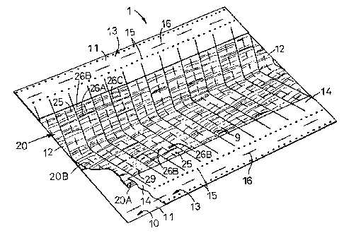
Fig. 3 is a fragmentary scale-enlarged perspective view
showing an important part of Fig. 2. The sealing lines 9 are
formed by heating the base sheet layer 10 together with an
assembly of the long fibers 25 under a pressure exerted to them
so that they are pressed against each other in the direction
of thickness. The assembly of the long fibers 25 is bulky and
the finished wipe-out sheet 1 is formed with a plurality of
troughs 26C in the vicinity of the sealing lines 9 compressed
CA 02369254 2001-10-09
11-105956
_g_
at a high density as a result of the heating under a pressure.
Lengths of the long fibers 25 continuously extending between
each pair of the adjacent sealing lines 9 form the convex
bridge-like portions 26A describing arcs which are convex
upwardly of the base sheet layer 10. The lengths of the long
fibers 25 extending each pair of the adjacent sealing lines 9
are partially severed in tow, respectively, to form the fluffy
portions 26B.
The heat-sealable base sheet having been assembled with
the wiper layer 20 in the manner as has been described above
may be provided along its opposite long side edge regions with
the reinforcing sheets 13 bonded thereto and then cut into
predetermined lengths to obtain the individual wipe-out sheets
1. The wiper layer 20 is defined preferably 10 - 100 mm, more
preferably 20 - 60 mm inside the outermost edges of the long
side edge regions 11 of the base sheet layer 10. With such
arrangement, the wipe-out sheet 1 can be easily clipped to the
base plate 3 (See Fig. 1) and the long fibers 25 can be
economically used because the long fibers 25 are gathered to
the transversely middle zone of the wipe-out sheet 1. The
opposite short side regions of the wiper layer 20 may be
substantially aligned and sealed with the opposite short side
edge regions 12 of the base sheet layer 10, respectively, to
CA 02369254 2001-10-09
11-105956
-9-
improve a tear strength of the base sheet layer 10 along its
opposite short side edge regions 12.
Fig. 4 is a fragmentary sectional illustrating the base
sheet layer 10 realized in different manners as illustrated by
(A) - (C) . Fig. 4 (A) illustrates a two layer laminated base
sheet layer 10 comprising two different types of synthetic resin,
i.e., a heat-sealable layer 31 participating in sealing with
the long fibers 25 and a non-heat-sealable layer 32 not
participating in sealing with the long fibers 25. The
heat-sealable layer 31 has a melting point lower than a melting
point of the non-heat-sealable layer 32 and is easily sealed
with the long fibers 25. A difference between the melting
points of these two base layers 31, 32 is preferably 70 °C or
higher so that the non-heat-sealable base layer 32 may be free
from deformation as well as damage even when the heat-sealable
base layer 31 is heated at a temperature higher than its melting
point. The base sheet layer 10 of this construction can be
obtained using polyethylene resin as the heat-sealable base
layer 31 and polyester resin as the non-heat-sealable base layer
32.
Fig . 4 ( B ) illustrates a three layer laminated base sheet
layer 10 comprising two different types of synthetic resin.
Upper and lower layers are defined by the heat-sealable base
CA 02369254 2001-10-09
11-105956
-10-
layers 31 and the non-heat-sealable base layer 32 is disposed
between the heat-sealable layers 31. The base sheet layer 10
of this construction enables the long fibers 25 to be heat-
sealed with both surfaces of this base sheet layer 10.
Fig. 4 (C) illustrates a base sheet layer 10 made of a
nonwoven fabric comprising core-sheath type conjugated fiber
33. Component fibers of the conjugated fiber 33 are
mechanically entangled and/or heat-sealed together to form the
nonwoven fabric. In the conjugated fiber 33, the sheath 36 leas
a melting point lower than a melting point of the core 37
preferably at least by 30 °C, more preferably at least by 70 °C.
With the base sheet layer 10 of this construction, the core 3?
maintains its initial shape even when the sheath 36 is molten
to be heat-sealed with the long fibers 25. Accordingly, the base
sheet layer 10 itself also can maintain its function as well
as its shape. This base sheet layer 10 enables the long fibers
25 to be heat-sealed with both surfaces of the base sheet layer
10.~ Polyethylene resin may be used for the sheath 36 and
polypropylene resin may be used for the core 37.
Fig. 5 is a fragmentary sectional view illustrating the
long fibers 25 forming the bridge-like portion 26A. While the
long fibers 25 comprise core-sheath type conjugated fiber,
preferably comprise mechanically crimped or heat-crimped
CA 02369254 2001-10-09
11-105956
-11-
conjugated fiber, Fig. 5 illustrate the long fibers 25 having
no crimps. The sheath 46 has a melting point lower than a
melting point of the core preferably at least by 30 °C, more
preferably at least by 70 °C. When the long fibers 25 are pressed
against the base sheet layer 10 under heating in order to seal
them with the base sheet layer 10, a press temperature is
adjusted to a temperature higher than the melting point of the
sheath 46 preferably by 20 °C or more, and more preferably by
60 °C but lower than the melting point of the core 47. At such
press temperature, the core 47 maintains each of the long fiber
25 in its initial shape, for example, so that this long fiber
25 reliably describes the arc. Polyethylene resin may be used
for the sheath 46 and polyester resin may be used for the core
47.
It is desired that the base sheet layer 10 and the long
fibers 25 are simultaneously molten and thereby rapidly as well
as reliably heat-sealed together. To this end, materials for
the base sheet layer 10 and the long fibers 25 are preferably
selected so that a difference between the melting points of the
components to be heat-sealed together may be limited to a level
less than 20 °C. For example, the heat-sealable layer 31 of
the base sheet layer 10 illustrated in Fig. 4 and the conjugated
fiber's sheath 46 constituting the long fibers 25 illustrated
CA 02369254 2001-10-09
11-105956
- 12-
in Fig. 5 are preferably made of polyethylene resin having
substantially the same melting point.
According to this invention, the core-sheath type
conjugated fiber is used as material for the long fibers forming
the wiper layer of the wipe-out sheet so that the melting point
of the sheath is lower than the melting point of the core
preferably at least by 30 °C, more preferably at least by 70 °C.
Selection of such relationship between the core and the sheath
in the conjugated fiber enables the wipe-out sheet to be
mass-produced at a high rate without deformation of the long
fibers even if a temperature of the press used to seal the long
fibers with the base sheet layer is relatively high.
According to this invention, the synthetic resin sheet
forming the base sheet layer of the wipe-out sheet also
comprises the layer having a relatively high melting point and
the layer having a relatively low melting point so that the layer
having the relatively low melting point may be heat-sealed with
the long fibers. In this manner, the productivity for the
wipe-out sheet is further improved.