Note: Descriptions are shown in the official language in which they were submitted.
CA 02369366 2001-10-04
IPEAAS
DIVERLESS SUBSEA HOT TAP SYSTEM
BACKGROUND OF THE INVENTION
1. Field of the Invention.
The present invention relates to a diverless process for tapping a pressurized
subsea
pipeline without removing the pipeline from service. This diverless process
utilizes
specialty clamping equipment, tapping equipment and remote operating vehicles
for
operating at water depths beyond that accessible by divers.
2. Prior Art.
Various kinds of underwater pipeline work have been carried out using divers
equipped with various tools. Deep water conditions entail high subsea pressure
and
dangerous conditions. Manned or diver equipped operations are not suitable if
the pipeline
is at a depth which is inaccessible by divers.
Remote operating vehicles perform visual and operational functions that are
more
limited than those functions performed by divers. To compensate for this
limitation,
processes must be developed to adapt the available technology to the work
requirements.
These processes are typically referred to as "diverless". Developed diverless
processes are
easily adapted for use using divers and/or control from the sea surface in
diver accessible
water depths.
It has been proposed in the past to utilize a diverless underwater pipe tap
system. De
Sivry et al. (USPN 4,443,129) discloses an example of a diverless underwater
pipe tap
system including a lifting device to engage and displace the pipe, a working
platform
installed vertically above the tapping region and various tools used to carry
out operations
including concrete stripping, ovality or roundness measurement, and a tapping
operation.
...wan ~
CA 02369366 2001-10-03
WO 00/60262 PCT/US00/07325
2
De Sivry et al. contemplates cutting out a section of the pipeline. There is
no disclosure or
suggestion of a tap procedure while the pipeline is under pressure and de
Sivry would not
be suitable for such an operation.
Likewise, various hot tap machines for tapping into a pipeline while the
pipeline is
pressurized have been disclosed. Reneau et al. (USPN 4,223,925) discloses one
exaniple
of a hot tap machine for an underwater pipeline. It is advantageous to perform
work on the
pipeline without interrupting the flow of liquids or gases therethrough.
It is also known to provide a remote operated subsea vehicle (ROV) controlled
from
the surface which includes thrusters or other mechanisms for propelling it
through the water
in response to a source of power at or controlled from the surface.
Brooks et al. (Re27,745) illustrates an example of a submersible wireline
robot unit
that may be controlled remotely.
None of the foregoing would be suitable for deep water conditions where the
external
subsea pressure is extreme.
Given that the life spans of certain deep water oil and gas developments will
be
coming to an end in the near future, there will be an increasing number of
existing pipelines
which have excess transport capacity, thereby leaving excess pipeline
infrastructure in deep
water locations.
If production from new fields can be tied into existing pipelines, then the
investment
in the pipeline can be spread out over more than one development. A diverless
hot tap
capability would allow the extension of pipelines from new fields to be
connected to existing
pipelines. This will reduce the overall length of the pipeline required to
support a new field.
CA 02369366 2001-10-03
WO 00/60262 PCT/US00/07325
3
It would also be possible to lay new trunk lines into areas in order to
support multiple
future field developments which would use lateral pipelines without having to
pre-install
connection facilities and valves at predetermined locations along the
pipeline.
Additionally, in deep water oil and gas developments, the cost of the pipeline
infrastructure is estimated to be the majority of the cost of all of the
installed subsea
equipment.
As an alternative to diverless hot tap systems, it would be possible to take
an existing
line out of service, cut a section of the pipeline and bring it to the
surface, install a valve,
lower the section back to the bottom and reconnect with a suitable jumper.
Such an
approach is not only time-consuming but requires the pipeline to be out of
service. It would
also be possible to pre-install blind branch connection facilities in the
pipeline for future tie-
ins. A disadvantage is that a great number of branch facilities would have to
be installed to
cover all possible future tie-in locations, a procedure that would be both
time-consuming and
expensive.
Notwithstanding the foregoing, there remains a need for a diverless process of
tapping a deep water subsea pipeline under high pressure without removing the
pipeline
from service.
CA 02369366 2001-10-03
WO 00/60262 PCT/USOO/07325
4
SUMMARY OF THE INVENTION
The invention described herein is a diverless process for tapping into a deep
water,
pressurized subsea pipeline without removing the pipeline from service. This
invention
provides a method to hot tap into an existing subsea pipeline and connect a
second, or
multiple, pipelines by means of a horizontal pull-in and connection process.
The initial phase will be locating a desired position of the hot tap along the
pipeline
and determining the in-situ conditions at that location. Various means such as
subsea
cameras, side-scan sonar, towed vehicles and remotely operated vehicles (ROV)
may be
used to locate and identify an area of interest. A preferred location on the
pipeline will be
indicated by the absence of any circumferential or longitudinal welds.
After the desired area of interest and pipe section have been located, it may
be
necessary to excavate soil, sand or silt from underneath the pipeline to
provide access for the
hot tap equipment. A work-class ROV may be used to blow away the soil, sand or
silt or
a suction dredge may be used to remove it, thereby creating an excavated area
for installing
the hot tap equipment. It may then be necessary for the ROV to clean the
pipeline using a
hydraulically operated brush or low pressure water jet.
In the next stage, two or more pipe lifting frames will be lowered from the
surface
and aligned by the ROV to straddle the pipeline during positioning. The
lifting frames will
be spaced at appropriate positions along the pipeline to effectively lift the
pipeline without
exceeding its plastic limit or otherwise damaging the pipeline. The distance
between, and
the number of lifting frames required, will be dependent upon the pipe size,
wall thickness,
internal pressure, soil conditions and other site-specific parameters.
Each of the lifting frames incorporates a pipe grip mechanism that can move
CA 02369366 2001-10-03
WO 00/60262 PCT/USOO/07325
transverse or perpendicular to the axis of the pipeline and lowered onto the
pipeline using
hydraulic supply and controls provided by the ROV. The pipe lifting frames are
also fitted
with mud mats that may be extended or retracted by the ROV to provide sea bed
stability.
After the lifting frame is positioned over the pipeline at the desired
location, the pipe
5 grip mechanism is lowered onto the pipeline using the ROV hydraulic supply
and controls.
After the pipe grip is lowered and brought into contact with the pipeline, the
grip mechanism
is closed securely around it and hydraulically locked. The pipe grip
mechanism, then
supporting the pipeline, is raised to the desired height above the sea bed by
the ROV using
a mechanical jack screw device or hydraulic means. The second pipe lifting
frame is landed
and operated in a similar manner so that the pipeline is supported by at least
two lifting
frames.
When the pipeline has been raised to the desired height by the pipe lifting
frames,
a measurement tool will be lowered from the surface on to the pipeline to
check pipe
roundness, ovality and axial alignment or straightness. The measurement tool
will be guided
into position and then powered and controlled by the ROV.
After the pipeline has been checked for ovality and straightness, the
measurement
tool will inspect the pipeline condition at the desired hot tap area and note
any anomalies or
welds in the area. In the event that the pipeline contains a longitudinal weld
that would
affect the sealing area, a weld bead removal tool will be lowered from the
surface and guided
onto the pipeline by the ROV. The ROV will then operate the weld bead removal
tool to
machine the weld flush with the pipe surface.
In the next stage, a pipe fitting frame assembly will then be lowered over the
pipeline
at the desired hot tap location. The pipe fitting frame assembly will include
a hot tapping
CA 02369366 2001-10-03
WO 00/60262 PCT/US00/07325
6
machine pre-installed at surface level on a hot tap fitting clamp by means of
a releasable
connector. The hot tapping machine and hot tap fitting clamp are integrated
together into
the pipe fitting frame. The hot tap cutter will be in retracted position
during lowering to
preclude initial contact with, and possible damage to, the pipeline.
After the pipe fitting frame has landed out on the pipeline, it is secured to
the pipe
by means of two ROV-operated pipe clamps located at opposite ends of the
frame. Next,
the hot tap fitting clamp is extended to the pipe and closed around it by
means of ROV-
supplied hydraulics and controls. After the hot tap clamp has been closed
around the pipe,
the ROV will tighten each of the clamp bolts. After the hot tap clamp has been
securely
tightened, the ROV will confirm that the hot tap isolation valve is open.
Next, the ROV will
perform an external seal test on the hot tap clamp and hot tapping machine
assembly prior
to making the hot tap.
Following a successful external seal test, the ROV will operate the hot
tapping
machine to perform the hot tap. The hot tapping machine will tap the pipeline
using its
cutter mechanism. When the hot tap operation has been completed and confirmed,
the ROV
will close the hot tap isolation valve and unlatch the hot tapping machine
from the releasable
connector hub which is located outboard of the hot tap isolation valve. The
hot tapping
machine and its support frame will then be retrieved to the surface.
In the next stage, a lateral pipe connector guide is lowered from the surface
and
guided into alignment stabs fixed to the pipe fitting frame. After the lateral
pipe connector
guide has landed out and secured to the pipe fitting frame, the ROV will pay
out two pull-in
cables from hydraulic winches mounted on the frame and attach them to the
lateral pipe
connector pull-in skid. The ROV then operates hydraulic winches to pull in the
lateral
pipeline connector to a position near the mating face of the releasable
connector hub.
CA 02369366 2001-10-03
WO 00/60262 PCTIUSOO/07325
7
Next, the ROV will stroke the lateral pipe connector to seat against the
mating hub
and sequentially lock the connector to the hub. To ensure the connector is
locked and to
confirm the sealing integrity of the connection, the ROV will perform a final
external seal
test.
Following a successful external seal test, the ROV then opens the hot tap
isolation
valve which permits product flow to the lateral pipeline system. Finally,
after the pipeline
has been connected and tested, the lateral pipe connector guide and associated
equipment
are retrieved to the surface.
An alternate method of the embodiment is now described. During the initial
stages
of the process, a pipeline will be located and a preliminary visual condition
inspection will
be conducted through use of cameras. Cameras would be incorporated in a remote
operating
vehicle which is known in various configurations. The pipeline will be
inspected in the area
of interest and a pipe section will be identified. If the pipe contains a
longitudinal weld or
seam, the location of the seam will be identified. It is preferred, but not
required, to select
a location where a weld seam is not cut out with the hole being bored into the
pipe during
the tapping operation. For seamless pipe, this step is ignored. Additionally,
a location will
be identified away from any circumferential weld so that no section of the hot
tap fitting will
be over a circumferential field weld joint.
Soil will be excavated from underneath the pipeline at the chosen location to
allow
unrestricted installation of the tools. The remote operating vehicle will be
utilized to remove
soil from underneath the pipeline and create a hole or an exposed area. The
pipeline will be
cleaned using a brush and/or a low pressure water jet powered by the remote
operating
vehicle.
CA 02369366 2001-10-03
WO 00/60262 PCT/US00/07325
8
Once the foregoing preliminary procedures have been completed, a measurement
tool
will be lowered from the surface on to the pipeline in order to check
circumferential
roundness or ovality of the pipeline while simultaneously checking the
straightness of the
pipeline. The measurement tool will be powered by the remote operating
vehicle.
A pair or more of pipe lift frames will be lowered from the surface to
straddle the
pipeline, the lift frames spaced as appropriate, along the pipeline axis, and
on opposing sides
of the hot tap location. Each pipe lift frame will include a pair of platforms
containing screw
or hydraulic mechanisms, located on each side of the pipeline, which are used
to position
and raise or lower a pipeline lifting tong.
Between the pair of platforms is a transverse beam from which extends the pipe
tong.
Each pipe tong may be positioned transversely to the axis of the pipeline and
lowered onto
the pipeline using the hydraulic system from the remote operating vehicle or a
mechanical
screw. Each lift platform may also include a mud mat which is adjustable with
respect to
the lift frame.
The lift frames will position the pipeline to a desired height in an even and
incremental sequence by the aforementioned mechanical or hydraulic mechanisms
contained
in each of the platforms thereby creating an upward net force. The mechanisms
are powered
by the remotely operated vehicle (ROV) in the same manner as the
aforementioned tong and
its associated manipulation mechanism. Subsequently, the pipe tongs are
mechanically
locked onto the pipeline in an elevated position.
After lifting the pipeline in preparation for installation of the hot tap
fitting clamp
assembly around the pipeline, the measurement tool will again be utilized to
check the
circumferential roundness or ovality and straightness of the pipeline.
CA 02369366 2001-10-03
WO 00/60262 PCT/US00/07325
9
In the event the pipeline contains a longitudinal weld and it is deemed
necessary to
remove the protruding surface of the weld, a weld bead removal tool will be
lowered from
the surface and landed onto the pipeline. The remote operating vehicle will be
docked into
the weld bead removal tool and hydraulic and control connections will be made.
The weld
bead removal tool will remove any protrusion of the longitudinal weld by
machining a
section of the weld along the pipeline.
In the next step of the sequence of the invention, a hot tap fitting clamp
assembly and
its associated orientation frame will be lowered from the surface and landed
on top of the
pipeline at the designated location between the lift frames. The hot tap
fitting clamp
assembly comprises the piping components for the lateral branch connection: a
clamp with
a branch port and with associated fasteners or studs, a valve having opening
and closing
features for the branch connection, and a connector hub for connection of the
hot tapping
machine and subsequently the lateral pipeline. These piping components are
preassembled
prior to being placed in the fitting and orientation frame.
The orientation frame includes a plurality of mud mats to support the hot tap
fitting
clamp assembly and hot tapping machine in soft soils. These mud mats can be
extended and
retracted by either hydraulic cylinders or mechanical screws so as to level
the frame and
support the weight of the equipment. The mud mats may be articulated to aid in
the
transportation and launching of the orientation frame.
Using the remote operating vehicle and its hydraulic system, the diverless hot
tap
fitting clamp assembly and orientation frame will be leveled.
In a preferred embodiment, the fitting and orientation frame includes four
uprights,
each of which is parallel to the other and each of the uprights are
perpendicular to the axis
CA 02369366 2001-10-03
WO 00/60262 PCT/US00/07325
of the pipeline. The orientation frame includes level indicators to measure
the tilt, if any,
and make leveling adjustments to the frame.
The orientation frame houses the hot tap fitting clamp assembly on supports
designed
to not obstruct the operation of closing the clamp body around the pipeline or
rotation of the
5 assembly about the pipeline. The hot tap fitting clamp assembly is made to
surround the
pipeline, in the closed position, by operating its own hydraulic pistons, or
mechanical
screws.
A plurality of guide posts are lowered from the surface onto the uprights of
the
orientation frame. The guide posts serve to guide and retain the hot tapping
machine to be
10 described herein. The guide posts are different lengths to facilitate the
landing of the
equipment.
The hot tap fitting clamp will be closed to surround the pipeline using
hydraulic
pistons or mechanical screws attached to the body of the clamp powered and
controlled by
the remote operating vehicle. The remote operating vehicle will also position
the fasteners
or studs for securing the body seals of the clamp. A torque tool or stud
tensioning assembly
will be lowered onto the guide posts, if not preinstalled with the hot tap
fitting clamp
assembly. The remote operating vehicle will be docked into the torque tool or
stud
tensioning assembly. Studs on the fitting clamp will thereafter be tightened
by said torque
tool or stud tensioning assembly. Upon completion of this operation, the
torque tool or stud
tensioning assembly will be retrieved to the surface.
Using a hydraulic piston and pinion arrangement, or other hydraulic mechanism
for
imparting a rotary motion, the hot tap fitting clamp assembly, which includes
a valve and
connector hub for the branch connection, is rotated from a side orientation to
an upright
CA 02369366 2001-10-03
WO 00/60262 PCT/US00/07325
11
position with respect to the pipeline. In the upright position, the valve will
be vertical and
parallel to the uprights and the guide posts. The remote operating vehicle
will actuate a grip
and seal mechanism in the hot tap fitting clamp to lock the hot tap fitting
clamp and to make
a seal with the pipeline. Finally, the pipeline will be lowered by the pipe
lift frames until
the pipeline is supported on the orientation frame.
The next operation describes a diverless method to connect the hot tapping
machine
to the hot tap fitting clamp assembly. The hot tap machine and its
accompanying frame will
be lowered onto the orientation frame through the use of the guide posts. The
hot tap
machine will be brought into position above and in approximate alignment with
the lateral
connection hub that is part of the hot tap fitting clamp assembly. The next
operation
involves the precision alignment of the connecting hubs (one on the hot tap
fitting clamp
assembly and one on the hot tap machine) and the landing of sealing surfaces
so as to avoid
damage in consideration of the weight of the equipment. The connectors are
designed with
various tapered surfaces to align the sealing faces as they are positioned for
contact by the
force of the weight of the top connector. An integral part of the connectors
are hydraulic
cylinders that control the final make-up of the two hubs. Additional hydraulic
cylinders are
used to latch and unlatch the hubs.
An alternate method for lowering the hot tap machine onto the connecting hub
would
involve a plurality of pistons, or other hydraulic mechanisms, attached to the
hot tap
orientation frame and the hot tapping machine which will control the height
and rate of
descent of the hot tap machine with respect to the hot tap frame. Once the hot
tap assembly
has been set in position using the guide posts, the hot tap machine will be
carefully lowered
through use of the pistons, or other hydraulic mechanisms, on the hot tap
frame and a seal
CA 02369366 2001-10-03
WO 00/60262 PCTIUSOO/07325
12
will be made with the hub of the connector on the hot tap fitting clamp
assembly. This
method would allow for other styles of connectors that do not have the
integral controlled
landing features to be employed.
The hot tap machine will tap the pipeline using its cutter mechanism by
passing
through the valve, in its opened position, and engaging the pipeline.
Thereafter, the cutter
of the hot tap machine and pipe coupon will be retracted and the valve will be
closed.
The pipe lift frames will then lower the pipeline and the accompanying fitting
clamp
back to the sea floor.
A series of steps will be taken to connect a production branch line or
extension of
another pipeline to the lateral hub of the hot tap fitting clamp assembly on
the existing
pipeline. With the production branch line terminating in a second production
hub and valve
assembly, the distance and relative orientation between the hot tap fitting
clamp assembly
as assembled on the pipeline and with the upright valve and connector hub on
the production
branch line will be measured. A pipeline jumper which contains mating
connector hubs for
connection at each end will be built to match the dimensions. The jumper is
then lowered
and guided by the remote operating vehicle onto the mating hubs at each
respective end by
the methods previously described in the setting of the hot tapping machine.
The jumper will
be lowered until the sealing faces meet. After the jumper is connected, the
various guide
posts and the pipe lift frames will be retrieved to the surface.
CA 02369366 2001-10-03
WO 00/60262 PCT/US00/07325
13
BRIEF DESCRIPTION OF THE DRAWINGS
Figure 1 illustrates an underwater deep sea pipeline residing on a sea floor
or sea bed
prior to the application of the present invention;
Figure 2 illustrates an example of a remote operating vehicle;
Figure 3 illustrates a measurement tool used in the process of the present
invention;
Figure 4 illustrates installation of a pair of pipe lift frames, part of the
process of the
diverless hot tap system of the present invention;
Figure 5 illustrates the pipe lift frame being lowered with accompanying mud
mats
retracted;
Figure 6 illustrates the pipe lift frame landed out on the sea floor and
positioned over
the pipeline;
Figure 7 illustrates the pipe lift frame clamped onto the pipeline and with
the pipeline
lifted off the sea floor for subsequent access;
Figure 8 illustrates the optional weld bead removal process;
Figure 9 illustrates the hot tap fitting frame being lowered with the hot
tapping
machine pre-installed on the frame;
Figure 10 illustrates the hot tap fitting frame landed out on the sea floor
and
positioned over the pipeline and between the pipe lift frames;
Figure 11 illustrates the pipe support clamps on both ends of the hot tap
fitting frame
closed around the pipeline;
Figure 12 illustrates the hot tap fitting clamps being aligned and closed onto
the
pipeline;
CA 02369366 2001-10-03
WO 00/60262 PCT/US00/07325
14
Figure 13 illustrates the hot tap clamps being tightened on the pipeline by
the remote
operating vehicle;
Figure 14 illustrates the ROV operating the hot tap machine to make the
pipeline hot
tap;
Figure 15 illustrates the hot tap machine being retrieved to the surface;
Figure 16 illustrates the hot tap machine support frame being retrieved to the
surface;
Figure 17 illustrates the lateral pipe connector guide being lowered into
position over
the hot tap fitting frame guideposts;
Figure 18 illustrates the lateral pipe connector guide landed out onto the hot
tap
fitting frame;
Figure 19 illustrates the lateral pipeline connector and skid assembly being
pulled
in to close proximity of an isolation valve;
Figure 20 illustrates the lateral pipeline connector aligned with and locked
on to the
isolation valve flange; and
Figure 21 illustrates the lateral pipe connector guide released from the hot
tap fitting
frame and being retrieved to the surface.
Figure 22 illustrates installation of a pair of pipe lift frames, part of the
process of
the diverless hot tap system of the present invention;
Figure 22A is an enlarged view of one of the pipe lift frames, which is part
of the
process of the present invention;
Figure 23 illustrates a weld bead removal tool on the pipeline, which is a
part of the
process of the present invention;
Figure 24 illustrates installation of an orientation frame containing the
assembly of
CA 02369366 2001-10-03
WO 00/60262 PCT/US00/07325
hot tap fitting clamp, valve and connecting hub installed on the pipeline
between the pipe
lift frames;
Figure 25 illustrates installation of the guide posts on the orientation frame
and the
use of a torque tool assembly to affix the hot tap fitting clamp on the
pipeline;
5 Figure 26 illustrates the hot tap fitting clamp and its repositioning from a
side
orientation to an upright orientation;
Figure 26A illustrates an enlarged view of the orientation frame to show
movement
of its pipe supports.
Figure 27 illustrates the lowering of a hot tap machine and accompanying frame
onto
10 guide posts of the orientation frame;
Figure 28 illustrates the initial alignment of the connector hub on the hot
tap fitting
machine and the hub on the lateral connection of the hot tap fitting clamp
assembly;
Figure 29 illustrates the final alignment utilizing hydraulic pistons or other
hydraulic
mechanism, on the hot tap frame to lower the hot tapping machine onto the hub
of the hot
15 tap fitting clamp assembly;
Figure 30 illustrates a production line and terminating production hub which
will be
connected to the pipeline;
Figure 31 illustrates the attachment of a pig catcher or pig launcher to the
production
hub prior to connection of the production line to the pipeline;
Figure 32 illustrates lowering of a jumper which is made to span between the
production hub and the fitting clamp;
CA 02369366 2001-10-03
WO 00/60262 PCT/US00/07325
16
Figure 33 illustrates lowering of the jumper in alignment with the production
hub
and the pipeline fitting clamp valve for use of the guide posts on the
orientation frame and
on the production frame;
Figure 34 illustrates the final lowering through use of valves on a jumper
frame to
bring the jumper into sealing alignment; and
Figure 35 illustrates the final connection of the jumper following which
removal of
the guide posts and pipe lift frames will be accomplished.
CA 02369366 2001-10-03
WO 00/60262 PCT/US00/07325
17
DETAILED DESCRIPTION OF THE PREFERRED EMBODIMENTS
The embodiments discussed herein are merely illustrative of specific manners
in
which to make and use the invention and are not to be interpreted as limiting
the scope of
the instant invention.
While the invention has been described with a certain degree of particularity,
it is to
be noted that many modifications may be made in the details of the invention's
construction
and the arrangement of its components without departing from the spirit and
scope of this
disclosure. It is understood that the invention is not limited to the
embodiments set forth
herein for purposes of exemplification.
Referring to the drawings in detail, Figure 1 illustrates a section of an
underwater
deep sea pipeline 12 residing on and supported by a floor 14 of a sea bed.
Figure 1, thus,
illustrates the pipeline 12 prior to application of the present invention. The
pipeline 12 will
consist of a number of sections joined together with a plurality of
circumferential welds 16.
Depending on the size of the pipeline and other factors, longitudinal welds
(not seen) may
also be encountered. Deep water locations, such as at 6,000 feet and below are
known to
produce high pressure conditions external to the pipeline, relative to the
internal pressure of
the pipeline. The present invention is adaptable to various diameter pipelines
but is
particularly useful for 10" to 20" diameter pipelines.
A remote operating vehicle (ROV) 18, shown in Figure 2, will assist in
performing
many of the steps or operations to be described in the present invention. The
remote
operating vehicle 18 will be controlled and may be powered from the surface.
Various
unmanned ROV's are well known in the field.
During the initial stages of the invention, the pipeline 12 will be located
and a series
CA 02369366 2001-10-03
WO 00/60262 PCT/US00/07325
18
of comprehensive procedures will be performed. Subsea cameras, side-scan
sonar, towed
vehicles and remotely operated vehicles (ROV) may be used to locate and
identify an area
of interest. A preliminary visual condition inspection will be conducted
through the use of
underwater cameras. The bottom conditions will be reported, the water current
will be
reported, the visibility surrounding the pipeline will be reported, the type
of soil on the sea
bed will be reported and the depth of the pipeline will be reported. Other
survey information
may be necessary and would be obtained. Additionally, the location of
circumferential pipe
seams and welds, if any, will be reported. The nature and condition of any
coating on the
pipeline, such as concrete or other material, will also be reported.
The pipeline 12 will be inspected in the area of interest and a pipe section
will be
identified between circumferential pipe welds 16. A preferred location on the
pipeline will
be the absence of any longitudinal welds that, if present, may be later
removed by a grinding
tool or similar mechanism operated by the ROV. A circumferential weld 16 will
be located
and then a location along the pipeline will be located a short distance from
the
circumferential weld so that there will be no section of the hot tap fitting
installed over or
immediately adjacent to the circumferential weld.
At the outset, soil, sand or silt will be excavated from underneath the
pipeline 12 to
allow unrestricted installation of tools to be described herein. In one
operation, the remote
operating vehicle 18 will employ a pump to create a jet of sea water to blow
away sand or
silt from underneath the pipeline and create an excavated or exposed area
beneath the
pipeline. Alternatively, the ROV 18 may employ a suction device to create the
desired
excavation.
CA 02369366 2001-10-03
WO 00/60262 PCT/US00/07325
19
Therefore, the pipeline 12 at the selected location will be cleaned using a
brush or
low pressure water jet powered and operated by the ROV. In some instances,
external
protective pipeline coating, such as fusion bonded epoxy, concrete or cement
and the like,
will be required to be removed prior to the next stage. A number of devices
have been
developed and are available to remove these coatings, and their use is
possible within the
scope of this invention.
Once the foregoing preliminary procedures have been completed, a measurement
or
metrology tool 30 as seen in Figure 3 will be lowered onto the pipeline 12
from the surface
at the selected location in order to check the circumferential roundness of
the pipeline while
simultaneously checking the axial alignment or straightness of the pipeline.
The
measurement tool 30 will be guided into position by the ROV and powered and
controlled
by the ROV's systems through the surface operator. The measurement tool moves
a probe
and camera back and forth axially as well as around circumferentially on the
pipe surface
to measure ovality and check for surface imperfections. If the pipeline is
determined to be
within the tolerances of roundness and straightness, the measurement tool may
be removed
and returned to the surface. Alternatively, the measurement tool 30 may be
left on, or
adjacent to, the pipeline 12 for use in a later sequence in the operation.
If the pipeline fails the roundness and straightness test at that location,
the
measurement tool 30 will be moved axially to another location on the pipeline
12 and the
measurement tests will be performed again until a satisfaction location is
found.
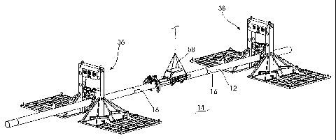
As illustrated in Figure 4, after a suitable location along the pipeline 12
has been
determined, a pair of pipe lifting frames, 36 and 38, will be lowered from the
surface to
straddle the pipeline 12. Figure 5 shows an enlarged drawing of one of the
lifting frames 36
or 38, as it is being lowered into position.
CA 02369366 2001-10-03
WO 00/60262 PCT/US00/07325
At least one pair of the pipe lifting frames will be utilized. In some
applications, four
lifting frames (only two shown) will be required to achieve the desired
results. Each lifting
frame 36 and 38 will include a pair of opposed structural guides 40 and 42 and
a cross-frame
44 upon which is installed a ROV control panel 46. Extendable mud mats 48 and
50 are
5 installed on each side of the lifting frame which can be rotationally
extended to provide
seabed support. In the present embodiment, the mud mats are positioned by
hydraulic
cylinders. Figure 5 shows the mud mats in the retracted, travel position.
Between the
vertical structural guides, 40 and 42, a transverse beam 52 is installed from
which extends
a pipe grip device 54.
10 The pipe grip device 54 may be moved transversely or perpendicularly to the
axis
of the pipeline 12 and lowered onto the pipeline 12 by means of a hydraulic
system provided
by the remote operating vehicle 18 and controlled through the ROV control
pane146. The
pipe grip device 54 may be brought to a desired height in an even and
incremental sequence
by the ROV-controlled hydraulic system 46 acting upon hydraulic cylinders or
other
15 extension mechanism (not shown) within the vertical structural guides, 40
and 42.
Before lifting the pipeline 12, the mud mats 48 and 50 are hydraulically
lowered into
position to rest securely on the seabed, as seen in Figure 6. In the present
embodiment, the
mud mats are positioned by hydraulic cylinders.
The pipe grip device includes a pair ofjaws which pivot to open or close.
Next, the
20 pipe grip device 54 is opened and lowered down to engage the pipeline 12.
After initial
contact, the pipe grip device 54 is closed around the pipeline 12 and
mechanically locked.
The pipeline 12 may then be raised to the desired elevated position, as best
seen in Figure
7.
CA 02369366 2001-10-03
WO 00/60262 PCT/US00/07325
21
This same sequence of operations is then repeated on each of the other pipe
lifting
frame or frames.
After both of the pipe lifting frames 36 and 38 have been installed as
described and
the pipeline 12 raised to the desired elevation, the measurement too130 will
again be utilized
to check the circumferential roundness and straightness of the pipeline 12.
If the measurement tool has not remained on the pipeline 12, it will be
reinstalled
between pipe lifting frames 36 and 38. The remote operating vehicle 18 will be
used to
power and operate the measurement too13 0. The roundness and straightness of
the pipeline
will again be checked in order to determine any effects of the aforementioned
pipe lifting
sequence. If the pipeline 12 is within the desired tolerances, the measurement
too130 will
be removed and retrieved to the surface. If the pipeline fails the measurement
check, the
pipe lifting frames may be repositioned and a new location selected for the
forthcoming hot
tap.
The next step in the sequence of the process, shown in Figure 8, will only be
performed if the pipeline 12 contains a longitudinal weld. A weld bead removal
tool 5 8 will
be lowered from the surface and landed onto the pipeline 12 in a manner
similar to the
measurement tool. The remote operating vehicle (not seen) will be docked into
the weld
bead removal too158 and will remove any longitudinal weld by grinding or
machining from
the pipeline. Confirmation of the weld bead removal tool 5 8 will be made
through a subsea
camera. After satisfactory weld bead removal, the removal too158 will be
removed from
the pipeline 12 and retrieved to the surface.
Prior to performing a subsea hot tap of the pipeline 12, a hot tap fitting
frame (to be
described in detail) will be inspected on the surface and prepared for
operation. The various
CA 02369366 2001-10-03
WO 00/60262 PCT/US00/07325
22
seals and slips of the hot tap machine and fitting frame will be inspected.
When the hot tap
machine is used with a ball valve, it will be connected and checked. The hot
tap machine
and pre-installed ball valve are then rigged for deployment.
Figure 9 illustrates the next sequence in the process. A hot tap machine 60
installed
on a fitting frame 62 together with the pre-installed ball valve 64 and pipe
clamp 66 is
lowered from the surface onto the pipeline 12. A hot tap machine support frame
and
horizontal structural guide 80 has also been mounted on the fitting frame 62
on the surface.
Hydraulically-operated pipe supports 68 and 70 are located at each end of the
fitting
frame 62 to capture the pipeline 12 after the frame has landed out on the
pipeline. The
combined hot tap machine/ball valve/pipe clamp assembly is supported in a
structural guide
system (not shown) within the lifting frame 62 that may be moved horizontally
away from
the pipeline during lowering and land out. The pipe clamp 66 is open at this
stage in order
to accept the pipeline 12 in a subsequent step.
Figure 10 illustrates the hot tap fitting frame 621anded out on to the
pipeline 12. The
pipe supports 68 and 70 and the pipe clamp 66 are open and the hot tap
machine/ball
valve/pipe clamp assembly is retracted away from the pipeline 12 to prevent
premature
contact and possible damage to the pipeline 12. Each pipe support 68 and 70
includes a pair
of U-shaped pieces that rotate between open and closed position.
In Figure 11, the ROV 18 has closed the pipe supports 68 and 70 at both ends
of the
fitting frame 62 and extended the hot tap machine/ball valve/pipe clamp
assembly
horizontally to contact the pipeline 12. After the hot tap machine/ball
valve/pipe clamp
assembly has been extended to contact the pipeline 12, the ROV 18
hydraulically closes the
pipe clamp 66 around the pipeline. Closing the pipe clamp 66 is accomplished
in three steps
CA 02369366 2001-10-03
WO 00/60262 PCT/US00/07325
23
- 1) the initial closing of the clamp 66; 2) subsequent tightening of the
structural bolts along
the side of the clamp 66; and 3) setting of the seals and packers by means of
bolts at the end
of the clamp 66. Other pipe clamp designs may embody alternate means to obtain
the same
required results (a structurally secure and leak-tight clamp) within the scope
of this
invention.
Figure 12 illustrates the ROV 18 tightening the structural bolts along the
side of the
pipe clamp 66 using a hydraulically-operated torque tool (not shown). To
ensure a positive
leak-tight seal, the ROV 18 will be capable of monitoring grip displacement
indicators and
the pressure seal between the pipeline 12 and pipe clamp 66.
In the next sequence as seen in Figure 13, the ROV 18 operates the hot tap
machine
60 using a cutter mechanism (not shown) to machine out the hot tap coupon.
Prior to
making the hot tap, the ROV 18 confirms that the pre-installed ball valve is
in the "open"
position. After making the hot tap, the hot tap cutter will be retracted
through the ball valve
64 and the ball valve will be "closed" by the ROV 18.
After the hot tap has been completed, the ROV 18 disconnects the hot tap
machine
60 from the ball valve 64 as shown in Figure 14. This is accomplished by means
of a
mechanical (bolted flange or hub) or hydraulic connection between the ball
valve 64 and hot
tap machine 60. The present embodiment illustrates the use of a hub-type
mechanical
connection 20 which requires only 1 or 2 actuation screws to install.
Figure 15 illustrates the hot tap machine 60 being retrieved to the surface.
The ball
valve 64 has been "closed" and the ROV 18 has checked the pipe clamp 66 and
ball valve
64 for any leakage.
Figure 16 illustrates the hot tap machine support frame and horizontal
structural
CA 02369366 2001-10-03
WO 00/60262 PCT/US00/07325
24
guide 80 being retrieved to the surface. This subassembly was supported and
oriented by
a plurality of vertical guideposts 82. An alternate configuration (not shown)
wherein the hot
tap machine, support frame and horizontal structural guide are integrated into
a single
system is within the scope of this invention.
In the next sequence seen in Figure 17, a lateral spool connector guide 84 is
lowered
from the surface and stabbed over the pair of vertical guideposts 82. After
initial guidance
by the ROV, the lateral connector guide 841ands out on the hot tap fitting
frame structure
62. Figure 18 shows the lateral spool connector guide 84 completely landed out
on the
fitting frame structure 62. The guide 84 includes a pair of opposed walls..
As seen in Figure 19, after the lateral spool connector guide 84 has landed
out on the
hot tap fitting frame 62, a lateral spool sled 88, having a production or
other branch pipeline
94, is brought in proximity with the structure 62. The ROV 18 pulls, in
sequence, wires
from a pair of small hydraulic winches 86 installed on the connector guide 84
out to a lateral
spool sled 88 which has been positioned near the pipeline 12. The ROV 18 then
attaches
the wires to structural points 90 on the sled 88. Next, the ROV 18 actuates
the hydraulic
winches 86 to pull the lateral spool sled 88 to a position within the
connector guide 84.
From that position, the sled 88 is guided to a final position wherein a
flowline connector 92
contacts a mating flange on the ball valve 64. The connecting pipeline, or
spool 94 is
connected to the existing pipeline 12 by means of the flowline connector 92.
A series of steps will next be taken to connect the existing pipeline 12 into
a
production branch or other unpressurized pipeline 94 by means of the lateral
spool tie-in to
be described herein. In a preferred example, the following steps occur.
CA 02369366 2001-10-03
WO 00/60262 PCT/US00/07325
As seen in Figure 20, after the flowline connector 92 has seated against a
corresponding flange on the ball valve 64, the ROV 18 hydraulically actuates
the connector
92 to firmly connect it to the ball valve. In the embodiment illustrated, a
collet connector
hydraulically locks the lateral spool to the ball valve 64 then seals off the
lateral
5 spool/connector hub interfaces. After this connection has been made, the ROV
18 will
perform a leak test of the interface and "open" the ball valve 64 to permit
fluid flow from
the existing pipeline 12 through the pipeline system.
After all checks and tests have been satisfactorily performed, the connector
guide 84
is retrieved to the surface and recovered as seen in Figure 21.
10 The foregoing describes connection of a production branch or other pipeline
to the
existing pipeline. Other configurations are possible within the scope of the
invention.
Once a suitable location on the pipeline 12 has been determined, a plurality
of pipe
lift frames, 120 and 122, will be lowered from the surface to straddle the
pipeline as best
seen in Figure 22. Figure 22A shows an enlarged drawing of one such pipe lift
frame 120.
15 In the present embodiment, at least a pair of pipe lift frames 120 and 122
will be
utilized. In some applications, four pipe lift frames (not shown) will be
utilized to achieve
the desired result. Each pipe lift frame 120 and 122 will include a pair of
opposed support
platforms 124 and 126 which will be lowered on opposite sides of the pipeline
12. Each
platform contains hydraulic or screw mechanisms. Between the platforms 124
and126 is a
20 transverse beam 128 from which extends a pipe tong 130.
Each pipe lift platform 124 and 126 may include a mud mat, lift bags (not
shown in
Figures 22 and 22A) or other methods of support.
CA 02369366 2001-10-03
WO 00/60262 PCT/US00/07325
26
The pipe tongs 130 may be moved transversely or perpendicular to the axis of
the
pipeline 12 and lowered around the pipeline 12 using the hydraulic system from
the remote
operating vehicle 18. The lift frames 120 and 122 will be brought to a desired
height in an
even and incremental sequence by the lifting device 132 and 134 contained in
each of the
platforms 124 and 126. In one preferred method, the hydraulic devices include
bags which
are actuated with hydraulic power supplied by the remote operating vehicle 18
(not shown
in Figure 22). Subsequently, the pipe tongs 130 are mechanically locked onto
the pipeline
12 in the elevated position.
Once the pipe lift frames 120 and 122 have been installed as described, the
measurement too130 will then again be utilized to check the circumferential
roundness or
ovality and straightness of the pipeline.
If the measurement tool has not remained on the pipeline 12, it will be
reinstalled on
the pipeline 12 between the lift frames 120 and 122. The remote operating
vehicle will be
docked into the measurement tool and the hydraulic and electronic control
connections will
be made. The roundness or ovality and straightness of the pipeline will again
be checked
in order to determine any effects of the foregoing pipe lifting on the pipe.
If the pipeline 12
is within the desired tolerances, the measurement too130 will be removed. If
the pipeline
fails the check, the pipe lifting frames may be readjusted and a new location
chosen for the
forthcoming hot tap.
The next step in the sequence shown in Figure 23 will only be performed if the
pipeline contains a longitudinal weld. If deemed necessary, a weld bead
removal tool 140
will be lowered from the surface and landed onto the pipeline 12 as shown in
Figure 23. The
remote operating vehicle 18 (not shown in Figure 23) will be docked into the
weld bead
CA 02369366 2001-10-03
WO 00/60262 PCT/US00/07325
27
removal tool 140 and the hydraulic and control connections will be made. The
weld bead
removal tool 140 will remove any protruding longitudinal weld by machining the
weld bead
from the pipeline 12. Thereafter, visual inspection through a camera will be
made. Finally,
the weld bead removal tool 140 will be removed from the pipeline and returned
to the
surface. The weld bead removal tool will be used in those instances where a
longitudinal
weld has been found and the tool must be removed prior to the hot tap to be
performed.
In a step to be performed prior to the tapping of the pipeline, a hot tap
fitting clamp
will be inspected and prepared for operation. The various seals on the hot tap
fitting clamp
will be checked. The hot tap fitting clamp will also be rigged for vertical
orientation.
The next step in the sequence of the invention is illustrated in Figure 24.
The pipe
lift frames 120 and 122 are lowered so that the pipeline 12 will likewise be
lowered. A hot
tap fitting and its associated orientation frame 148 will be lowered from the
surface and
landed on top of the pipeline 12 between the pipe lift frames 120 and 122. The
frame 148
may include a pair of opposed mud mats 150 (one visible in Figure 4). The mud
mats 150
are movable by hydraulic cylinders between an extended and retracted position.
The mud
mats will be placed in the retracted position during lowering. The mud mats
150 will be
extended and lowered before final touchdown on the sea floor 14. The mud mats
150 will
be operated by the remote operating vehicle hydraulic system.
Thereafter, the pipe lift frames 120 and 122 will be raised until the pipeline
12 is
fully seated in the saddles of the orientation frame 148. Using the remote
operating vehicle
hydraulics system, the orientation frame 148 will be leveled. Thereafter, the
pipe lift frames
120 and 122 will be locked in place.
CA 02369366 2001-10-03
WO 00/60262 PCT/USOO/07325
28
In the present embodiment, the orientation frame 148 includes four uprights
142,
144, 146 and 147, each of which is parallel to the other. It will be
appreciated that while a
plurality of uprights is advantageous, the number is a matter of choice.
The frame 148 also includes an associated hot tap fitting clamp assembly 154.
The
hot tap fitting clamp assembly comprises the piping components for the lateral
branch
connection: a clamp with a branch port and with associated fasteners or studs,
a valve
having opening and closing features for the branch connection, and a connector
hub for
connection of the hot tapping machine. The hot tap fitting clamp assembly 154
is lowered
over the pipeline at the selected location. The fitting clamp 154 is initially
closed using its
own hydraulic pistons and a plurality of fasteners or studs are pushed in. The
remote
operating vehicle (ROV) 18 will initially be used to hydraulically close the
fitting clamp
around the pipeline.
With reference to Figure 25, either before or after closing the fitting clamp
154, a
plurality of guide posts 160, 162, 164 and 166 are lowered from the surface
onto the uprights
142, 144, 146 and 147, respectively, of the orientation frame 148 to guide and
retain. While
the guide posts may be of various configurations, in the present embodiment
they have
frusto-conical shaped, open bases. The guide posts 160, 162, 164, and 166 are
of uneven
length allowing for easy landing of equipment. By stabbing one guide post at a
time, the
remote operating vehicle can guide the equipment into position.
A torque tool or stud tensioning assembly 170 is seen being lowered from the
surface
into position in Figure 25. The remote operating vehicle 18 will be docked
into the torque
tool or stud tensioning assembly 170 and the hydraulic and electronic control
connections
will be made. The fasteners or studs on the hot tap fitting clamp 154 will
thereafter be
CA 02369366 2001-10-03
WO 00/60262 PCT/US00/07325
29
tightened by the torque tool or stud tensioning assembly. Once this operation
has been
completed, the torque tool assembly or stud tensioning assembly 170 will be
retracted from
the guide posts and returned to the surface.
To facilitate the positioning of the hot tap fitting clamp on the pipeline as
just
described, a lateral connection valve 172 on the fitting clamp assembly 154
will be oriented
in a side position. Stated in other words, the connection valve 172 will not
be vertical to
the sea floor 14.
As shown in Figure 26, using a hydraulic piston and pinion or rotary actuator
arrangement, the fitting clamp 154 will include a connection valve 172 which
is rotated
approximately ninety degrees (90 ) from a side to an upright position. In the
upright
position, the valve will be vertical to the sea floor and parallel to the
uprights and the guide
posts. The hot tap fitting clamp and valve assembly will contain level
indicators to verify
that the valve is vertically oriented. These level indicators may be
electronic transponders
and/or visual scale measurement devices.
Thereafter, the remote operating vehicle 18 will actuate a grip and seal
mechanism
between the fitting clamp and the pipeline 12. The remote operating vehicle
(ROV) will be
capable of monitoring grip displacement indicators and the pressure. The
remote operating
vehicle 18 will hot stab into a test port and pressurize it to a predetermined
pressure to verify
a seal between the fitting clamp 154 and the pipeline 12. Accordingly, the
seal integrity is
tested. A relative vacuum/pressure test is performed using a remote operating
vehicle tool.
When the test is performed with the valve closed, it verifies the integrity of
the seal between
the pipeline 12 and the fitting clamp 154, the longitudinal seals along the
clamp body, and
the seal of the valve for pipeline pressure. In the case of a vacuum test, the
external pressure
of the water depth is verified.
CA 02369366 2001-10-03
WO 00/60262 PCTIUSOO/07325
Finally, as illustrated in Figure 26A, opposed pipe supports 171 rotate about
axes
173 (shown by dashed lines) to close to form U-shaped piece 174, the pipeline
12 will then
be lowered by the pipe lift frames 120 and 122 until the pipeline 12 is
supported on the
orientation and fitting frame 148. The U-shaped piece 174 receives and
supports the
5 pipeline 12.
The next step in the sequence of the present invention is illustrated in
Figure 27.
With the pipeline 12 lowered and supported by the orientation frame 148, a hot
tap machine
190 and accompanying frame 192 (forming a hot tap assembly) is lowered from
the surface
onto the orientation frame 148 through use of the guide posts 160, 162, 164
and 166. The
10 hot tap machine 190 and its frame 192 have been previously rigged together.
The same
guide post arrangement is used as described previously. The hot tap frame 192
includes
receptacles 180, 182, 184 and 186 which are received on the guide posts 160,
162, 164 and
166. While the receptacles 180, 182, 184 and 186 may take various forms, in
the present
preferred embodiment, they are frusto-conical with open bases. The hot tap
frame 192 may
15 include a plurality of pistons or mechanical screws 194 which control the
level of the hot tap
machine 190 with respect to the frame.
As seen in Figure 28, the hot tapping assembly will land on the orientation
frame
148. Initially, no seal is made so that the hot tap machine 190 is prevented
from accidentally
being rammed against the fitting clamp 154. In Figure 28, the hot tap machine
190 is aligned
20 with the connection valve 172.
Thereafter, as seen in Figure 29, the pistons 194 on the hot tap frame 192
will be
activated so that the hot tap machine 190 will be carefully lowered and a seal
will be made
between the hot tap machine 190 and the fitting clamp 154. The integrity of
the seal will
CA 02369366 2001-10-03
WO 00/60262 PCT/US00/07325
31
then be tested. If the aforementioned pressure test is conducted with the
valve open, it tests
the integrity of the connection between the hot tap machine 190 and fitting
clamp 154 as
well. The test medium is not water and is selected to avoid hydrate formation
which occurs
by a meta-stable combination of natural gas liquids and water at the ambient
pressures and
temperatures. The test medium utilized could be any of several different
methods, such as
glycol or methanol. It is introduced to the cavitie(s) by means of a low
pressure pump which
circulates inhibitor/test medium into the cavitie(s) and takes seawater
returns into a holding
tank. Once the seawater has been displaced by the inhibitor/test medium, the
pressure test
is conducted. The test is conducted by connecting a high pressure/vacuum pump
to a cavity
in the hot tap machine body. The pump will pressurize the cavity between the
top of the
ball-valve ball and the tap machine. A successful test verifies integrity of
the seal between
the hot tap machine and the male hub on the hot tap fitting. The ball valve is
then opened
and the test is repeated. A successful test verifies the sealing integrity of
the entire system.
The entire process is repeated with the pump in the vacuum mode. This verifies
integrity
of the sealing system when the hydrostatic (ambient) pressure is greater than
the pipeline
pressure.
After a good test is attained, the tapping will proceed. The remote operating
vehicle
18 will be docked into the control panel of the hot tap machine 190 and
hydraulic and
electronic connections made. The hot tap machine 190 will tap the pipe 12
using its cutter
mechanism (not visible). Thereafter, the cutter mechanism and pipe coupon will
be retracted
through the valve 172 and the valve will be closed. If deemed necessary, the
integrity of the
seal of the valve will be verified by testing on the external pressure side of
the valve (hot tap
fitting machine side) with the valve in the closed position.
CA 02369366 2001-10-03
WO 00/60262 PCT/USOO/07325
32
Finally, the hot tap machine 190 and its accompanying frame 192 will be raised
and
recovered to the surface in a reverse procedure. The entire procedure is
performed while
the pipeline is operational. The internal pressure of the pipeline may be
significantly above
or in deep sea conditions, below, ambient pressure.
If external pressure exceeds the internal pipeline pressure, it will be
necessary to
break the seal by pressuring the connection with the valve closed. The
internal pressure
would be raised to at least the external pressure so that there would be no
external forces
acting on the seal to prevent disconnection of the hot tapping machine.
The hot tap fitting clamp 154 is then released from the uprighting mechanism.
Thereafter, the pipe lift frames 120 and 122 will lower the pipe 12 and the
accompanying
hot tap fitting clamp assembly back toward the sea floor 14. The weight of the
pipeline 12
and the fitting clamp 154 are taken up by the orientation frame 148.
Accordingly, the weight
will not be distributed on the hot tap fitting or on the pipeline. The
orientation frame 148
is designed with sufficient dimensional tolerances so as to provide the
required flexibility
for the connection of the lateral pipeline and also provide support for the
weight of the
connecting pipeline in soft soils.
A series of steps will next be taken to connect a production branch or other
pipeline
to the existing pipeline 12. In a preferred example to be discussed herein, a
new production
line 200, as seen in Figure 30, is tied in to the pipeline 12. The production
line 200
terminates in a valve or upright production hub 202. The distance or relative
orientation
between the hot tap fitting as assembled and the valve hub 202 on the
production line is
measured.
CA 02369366 2001-10-03
WO 00/60262 PCT/US00/07325
33
The pipe lift frames 120 and 122 may be removed at this time or,
alternatively, may
be removed at the end of the procedure.
In Figure 31, a pig catcher 220 is guided onto the production hub so that the
production line 200 may be pigged prior to completion, all as known in the
art. A pair of
guide posts 214 and 216 are lowered on the uprights.
With reference to Figure 32, a jumper 230 is built to match the measured
dimensions.
The jumper 230 will be filled with methanol or glycol or a hydrate-inhibition
fluid prior to
being deployed subsea. Thejumper 230 is then lowered and guided by the remote
operating
vehicle 18 using techniques for setting jumpers previously described. As seen
in Figure 32,
the jumper assembly 230 is held by jumper frame 232 and is lowered on to male
end
connectors (one at the connection for the hot tap and one on the lateral
pipeline sled
structure). The connecting devices on the jumper contain hydraulic pistons to
land the
female collet connector on the sealing faces in a method to prevent damage to
the sealing
faces.
Finally, as seen in Figure 23, hydraulic cylinders 236 gradually lower
thejumper 230
until the sealing faces meet. Collet connectors then seal off the jumper
valve/hub interfaces.
Figure 34 shows the jumper 230 after it has been connected.
In a final step, as seen in Figure 35 the guide posts 160, 162, 164, and 166,
and the
pipe lift frames 120 and 122 are retrieved to the surface.
Whereas the present invention has been described in relation to the drawings
attached
hereto, it should be understood that other and further modifications, apart
from those shown
or suggested herein, may be made within the spirt and scope of this invention.