Note: Descriptions are shown in the official language in which they were submitted.
CA 02370229 2001-10-12
WO 99!56512 PCT/US99/08070
1
APPARATUS FOR THE REDISTRIBUTION OF ACOUSTIC ENERGY
FIELD OF THE INVENTION
This invention relates to reflective devices
that, when coupled with a transducer, are capable of
redistributing and broadly dispersing sound over a
broad spectrum of frequencies with little or no
distortion.
BACKGROUND OF THE INVENTION
It is well known in acoustics that the dispersion
pattern of a sound source is related to the size of
the radiating element. This causes conventional
electro-acoustic transducers, or loudspeakers, to have
an off-axis response that degrades with increasing
frequency. This has long been regarded as a basic
problem in loudspeaker design and over the years
several different solutions have been proposed. These
include the use of multiple transducers, horns and
waveguides, electrostatic elements, and acoustic
reflectors of varying shapes. Many of these solutions
have undesirable side effects such as the introduction
of frequency response anomalies and complicated
fabrication techniques. Furthermore, these systems as
well as conventional loudspeakers can act in
CA 02370229 2001-10-12
WO 99/56512 PCT/US99/08070
2
unpredictable ways in typical listening environments
due to the lack of consideration usually given to the
human auditory perceptual system.
The recreation of sound via loudspeakers can be
enhanced by controlling the direction, amplitude and
spectral content of the sound arriving at the
listener's ears via the loudspeaker/listening
environment combination. It is the purpose of this
invention to address all these issues in a single
device which is simple to manufacture. When properly
mated to a suitable conventional transducer, the
invention causes sound to be transferred to the
listening environment with a nearly frequency-
invariant horizontal dispersion pattern. This affords
a greater number of listeners with timbrally accurate
sound with a greater sense of envelopment due to
greatly enhanced lateral room reflections.
Furthermore, floor and ceiling reflections are reduced
causing increased stereophonic phantom image
stability. A number of the invention's features can
be modified to suit the designer's particular needs
when incorporating the invention into a complete
loudspeaker system.
CA 02370229 2001-10-12
WO 99/56512 PCT/US99/08070
3
SUMMARY OF THE INVENTION
The present invention addresses these concerns by
providing an apparatus for the redistribution of
acoustic power which comprises a base, a lens, and a
means for mounting the lens upon the base. The base
has an upper surface, a lower surface, a front
surface, and a rear surface. The rear surface of the
base is positionable upon a supporting surface. The
lens also has an upper surface, a lower surface, a
front surface, and a rear surface.
The front surface of the lens includes a
reflective surface, a point P lying on the reflective
surface, and at least one adjoining surface 81. A
line L passes through the point P and intersects the
lower surface of the base at a point B. A point F1
lies on the line L between the point P and the point
B. The reflective surface is defined by the surface
of revolution R1 of an elliptical arc A1 rotated about
the line L through an angle a1 and the surface of
revolution R2 of an elliptical arc A2 rotated about
the line L through an angle a2. The elliptical arc A1
constitutes a portion of an ellipse E1 having a focal
point located at the point F1 and having a lower end
terminating at the point P. The elliptical arc A2
constitutes a portion of an ellipse E2 having a focal
point located at said point F1 and having an upper end
CA 02370229 2001-10-12
WO 99/56512 PCT/US99/08070
4
terminating at said point P. The angle a1 is chosen
such that the surface of revolution R1 is convex with
respect to adjoining surface 81, and the angle a2 is
chosen such that the surface of revolution R2 is
concave with respect to adjoining surface 81.
A primary object of the present invention is to
provide an apparatus which redirects acoustic energy
radiated from a sound radiator positioned at or
proximate to focal point F1 such that the resulting
dispersion pattern is very broad over a very wide
frequency range horizontally and is limited
vertically.
A further object of the present invention is to
provide an apparatus which produces horizontally
redirected acoustic radiation which is substantially
free of frequency response anomalies.
Another object of the present invention is to
provide an apparatus with insulative surfaces
positioned to tailor the overall acoustic radiation
pattern.
Other objects and advantages of the present
invention will become apparent when the apparatus for
redistribution of acoustic radiation of the present
invention is considered in conjunction with the
accompanying drawings, specification, and claims.
CA 02370229 2005-07-05
4a
In a further aspect, the present invention provides an
apparatus for the redistribution of acoustic energy,
comprising: a base having an upper surface, a lower surface,
a front surface, and a rear surface, said lower surface
positionable upon a supporting surface; a lens having an
upper surface, a lower surface, a front surface, and a rear
surface; and means for mounting said lens upon said base;
said front surface of said lens including a reflective
surface, a point lying on said reflective surface, and at
least one adjoining surface, a line passing through said
point and intersecting the lower surface of said base at a
point, a point lying on said line between said point and said
point, said reflective surface defined by the surface of
revolution of an elliptical arc rotated about said line
through an angle and the surface of revolution of an
elliptical arc rotated about said line through an angle, said
elliptical arc having a lower end terminating at said point
and constituting a portion of an ellipse having a focal point
located at said point, said elliptical arc having an upper
end terminating at said point and constituting a portion of
an ellipse having a focal point located at said point, said
angle chosen such that said surface of revolution is convex
with respect to said adjoining surface, said angle chosen
such that said surface of revolution is concave with respect
to said adjoining surface.
CA 02370229 2001-10-12
WO 99/56512 PCT/US99/08070
BRIEF DESCRIPTION OF THE DRAWINGS
Figure 1 is a side plan view of an embodiment of
the inventive apparatus placed on a supporting surface
showing the boundary of an interior reflective surface
in phantom.
Figure 2 is a front plan view of an embodiment of
the inventive apparatus placed on a supporting
surface.
Figure 3 is a top plan view of an embodiment of
the inventive apparatus showing the boundary of the
exposed upper surface of its base member in phantom.
Figure 4 is a cross-sectional view of the
embodiment of the inventive apparatus of Figure 3
taken at section line 4-4 showing in phantom two
ellipses used in the formation of the reflective
surface of the inventive apparatus.
Figure 5 is a diagram depicting the formation of
the two surfaces of rotation which form the reflective
surface of the inventive apparatus by the rotation of
two elliptical arcs.
Figure 6 is a side view of an embodiment of the
inventive apparatus having a transducer mounted in a
tilted orientation on the upper surface of its base.
Figure 7 is a diagram showing the connection of
a high pass filter between a power amplifier for the
CA 02370229 2001-10-12
WO 99/56512 PCT/US99/08070
6
sound system and a transducer used with the inventive
apparatus.
DESCRIPTION OF THE PREFERRED EMBODIMENT
Referring to Figure 1, a preferred embodiment of
the inventive apparatus 1 for redistribution of
acoustic energy is shown. Apparatus 1 comprises a
base 10, a lens 30, and a means for mounting lens 30
upon base 10. Base 10 has an upper surface 12, a
lower surface 14, a front surface 16, and a rear
surface 18. Lower surface 14 is configured such that
base 10 is positionable upon a supporting surface 20.
Supporting surface 20 shown here is planar; it should
be understood, however, that supporting surface 2o can
be any surface upon which the user desires to place
the inventive apparatus 1.
Lens 30 has an upper surface 32, a lower surface
34, a front surface 36, and a rear surface 38.
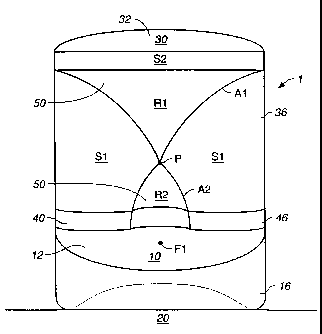
Referring to Figure 2, front surface 36 includes, but
is not limited to, a reflective surface 50, a point P
lying on reflective surface 50, and at least one
adjoining surface 81. Additional adjoining surfaces
such as 82 may also be designed.
Reflective surface 50 is configured to provide
optimal dispersion of acoustic radiation emitted from
a transducer, and is defined by two surfaces of
revolution R1 and R2. Referring to Figure 4, a line
CA 02370229 2001-10-12
WO 99/56512 PCT/US99/08070
7
L passes through the point P lying on reflective
surface 50 and intersects the lower surface 14 of base
at a point B. Two ellipses E1 and E2 can then be
chosen such that point P is located on each ellipse E1
and E2, and ellipses E1 and E2 share a common focal
point F1 which lies on line L between point P and
point B. Ellipse E1 then will have a second focal
point F2~, and ellipse E2 will have a second focal
point F22. Ellipse E1 defines an elliptical arc A1
having a lower end terminating at point P, and ellipse
E2 defines an elliptical arc A2 having an upper end
terminating at point P. Referring to Figure 5,
surface of revolution R1 is formed by rotating
elliptical arc A1 through an angle a1, and surface of
revolution R2 is formed by rotating elliptical arc A2
through an angle a2. Angle a1 should be chosen such
that surface of revolution R1 is convex with regard to
adjoining surface S1; angle a2 should be chosen such
that surface of revolution R2 is concave with regard
to adjoining surface 81.
In an embodiment of the inventive apparatus, the
length of elliptical arc A1 is varied constantly as it
is rotated about line L at angles al, while arc A1
always terminates at lower point P. Effectively, this
allows the user to produce a number of variances upon
reflective surface R1, each having a different upper
boundary.
CA 02370229 2001-10-12
WO 99/56512 PCT/US99/08070
8
Referring to Figure 6, in operation, a transducer
60 is positioned at or proximate to point F1.
Acoustic radiation is emitted from F1 and disperses
outward in all directions from the transducer's
emissive area. Acoustic radiation dispersing towards
lens 30 is reflected by reflective surface 50.
While ellipses E1 and E2 may be any two ellipses
selected to have the appropriate focal point F1, point
P, and arc A1 or A2 described above, they are
preferably chosen such that most acoustic radiation
striking surfaces R1 and R2 will be reflected upon
paths which have a limited vertical component and a
broad horizontal component. It should be understood,
however, that the directivity of the reflected
acoustic radiation, will depend upon many factors
including, but not limited to, the positioning of the
sound radiator producing the reflected acoustic
radiation and the orientation of the reflective
surface 50 with regard to the surrounding environment.
The choice of ellipses E1 and E2 and the exact
positioning of transducer 60 can be tailored to
produce optimal effects.
Transducer 60 may be tilted as shown in Figure 6,
thus changing the direction at which the acoustic
energy emitted from the transducer is radiated. The
degree to which transducer 60 is tilted, which can be
measured by an angle p made between an axis 62 of the
CA 02370229 2001-10-12
WO 99/56512 PCT/US99/08070
9
transducer 60 and the line L, can be varied to tailor
the overall frequency response and vertical
directivity of the apparatus.
Referring to Figure 4, the surfaces of apparatus
1 other than reflective surface 50 also affect the
overall sound production. Means for mounting lens 30
upon base 10 preferably comprises an absorptive
material insulator 40 having an upper surface 42, a
lower surface 44, a front surface 46, and a rear
surface 48. Lower surface 44 of insulator 40 is fixed
upon upper surface 12 of base 10. Lower surface 34 of
lens 30 is fixed upon upper surface 42 of insulator
40.
Insulator 40 may be composed of felt or any other
appropriate absorptive material. Note that the
vertical thickness of insulator 40 has been made large
in Figures 1 and 4 for purposes of clarity of
illustration. Benefits of the use of insulator 40
include, but are not limited to, the reduction of
acoustic resonances that might otherwise degrade
performance.
The placement of insulator 40 may define a first
covered portion 17 and a second uncovered portion 19
of the upper surface 12 of base 10. The uncovered
portion 19 of upper surface 12 may slope downwardly.
Benefits of such downward sloping include, but are not
limited to, the tailoring of vertical dispersion to
CA 02370229 2001-10-12
WO 99/56512 PCT/US99/08070
suit the needs of the designer. It should be
understood that absorptive material insulator could
entirely cover upper surface 12 of base 10, if
increased sound absorption is desired.
Similarly, adjoining surfaces 81 and 82 may be
covered with some absorptive material 72 to absorb
acoustic radiation which would otherwise reflect from
them. This technique can be used to tailor overall
system frequency response and limit the amount of
horizontal dispersion.
Considering the exterior surfaces of apparatus 1,
curved surfaces will typically produce fewer
disruptive diffraction effects. Accordingly, front
surface 16 preferably forms a curvilinear arc, such as
a generally elliptical or circular arc. Additionally,
the rear surfaces 18, 38, and 48 of the base 10, lens
30, and insulator 4o preferably together form a rear
surface 70 which is curvilinear and connects lower
surface 14 of the base 10 to upper surface 32 of the
lens 30. Preferably at least a portion of lower
surface 14 is curvilinear and slopes upwardly to meet
rear surface 70. Lower surface 14 and front surface
16 of base 10, rear surface 70, and upper surface 32
of lens 30 may also be covered with absorptive
material 72 to inhibit diffraction effects.
All conventional transducers have a sound power
output that increases with decreasing frequency.
CA 02370229 2001-10-12
WO 99/56512 PCT/US99/08070
11
Since the apparatus equally redistributes sound power,
the overall response of the system will have a
corresponding rising response with decreasing
frequency. Referring to Figure 7, to address this
problem, in a preferred embodiment a simple high pass
filter 100 which decreases electrical energy with
decreasing frequency is connected to the transducer 60
of the inventive apparatus. The output of a signal
source 110 used to drive the sound system passes
through filter 100, causing the system to have an
output at all frequencies that is substantially equal.
Where multiple transducers 60 are installed in a sound
system employing the apparatus, the filter may be part
of the crossover network used to connect the multiple
transducers 60.
While the inventive apparatus has been described
in terms of redistributing acoustic energy, it should
be understood that the inventive apparatus could also
be used to redistribute other energy waveforms such as
electromagnetic waves.
Although the foregoing invention has been
described in some detail by way of illustration for
purposes of clarity of understanding, it will be
readily apparent to those of ordinary skill in the art
in light of the teachings of this invention that
certain changes and modifications may be made thereto
CA 02370229 2001-10-12
WO 99/56512 PCT/US99/08070
12
without departing from the spirit or scope of the
appended claims.