Language selection

Search

Patent 2370449 Summary

Third-party information liability

Some of the information on this Web page has been provided by external sources. The Government of Canada is not responsible for the accuracy, reliability or currency of the information supplied by external sources. Users wishing to rely upon this information should consult directly with the source of the information. Content provided by external sources is not subject to official languages, privacy and accessibility requirements.

Claims and Abstract availability

Any discrepancies in the text and image of the Claims and Abstract are due to differing posting times. Text of the Claims and Abstract are posted:

  • At the time the application is open to public inspection;
  • At the time of issue of the patent (grant).
(12) Patent: (11) CA 2370449
(54) English Title: WATER JET
(54) French Title: HYDROJET
Status: Term Expired - Post Grant Beyond Limit
Bibliographic Data
(51) International Patent Classification (IPC):
  • B05B 9/04 (2006.01)
  • B08B 3/02 (2006.01)
  • F04F 1/06 (2006.01)
(72) Inventors :
  • NOESTHEDEN, ANDREW (Canada)
(73) Owners :
  • VALIANT CORPORATION
(71) Applicants :
  • VALIANT CORPORATION (Canada)
(74) Agent: SMART & BIGGAR LP
(74) Associate agent:
(45) Issued: 2011-01-04
(22) Filed Date: 2002-02-04
(41) Open to Public Inspection: 2002-08-14
Examination requested: 2006-11-06
Availability of licence: N/A
Dedicated to the Public: N/A
(25) Language of filing: English

Patent Cooperation Treaty (PCT): No

(30) Application Priority Data:
Application No. Country/Territory Date
09/783,260 (United States of America) 2001-02-14

Abstracts

English Abstract


A water jet is disclosed having a tank which forms a reservoir
containing a liquid, such as water. An elongated conduit has one end fluidly
connected to the reservoir while a nozzle is connected to the other end of the
conduit. This nozzle, furthermore, has an opening with a cross-sectional area
less than the cross-sectional area of the conduit. A valve is connected in
series
between the conduit and the reservoir, and this valve is movable between an
open and a closed position. The reservoir is pressurized to a pressure in the
range of 30-300 psi so that, once the valve is opened, water flows through the
conduit and out through the nozzle at a high pressure and high speed water
jet.
This water jet can be used, inter alia, to clean industrial parts, such as
engine
blocks.


French Abstract

Dispositif de jet d'eau doté d'un réservoir contenant un liquide, comme de l'eau. Un conduit allongé comporte une extrémité raccordée au réservoir qui permet au liquide de s'écouler tandis qu'une buse est raccordée à l'autre extrémité du conduit. La buse comporte aussi une ouverture dont le diamètre est inférieur à celui du conduit. Un robinet-vanne est connecté en série entre le conduit et le réservoir. Le robinet-vanne peut s'ouvrir et se fermer. Le réservoir est sous pression, à une pression de 30 à 300 livres par pouce carré. Lorsque le robinet-vanne est ouvert, l'eau s'écoule par le conduit et sort en un jet par la buse à haute pression et à haute vitesse. Le jet d'eau peut servir, entre autres choses, à nettoyer des pièces industrielles comme des blocs-moteurs.

Claims

Note: Claims are shown in the official language in which they were submitted.

8
We claim:
1. A method for cleaning debris from a passageway in an industrial part
comprising the steps of:
creating a pressurized source of liquid,
connecting one end of an elongated fluid conduit to a valve fluidly
connected with said pressurized source of liquid, said conduit having a
reduced
cross sectional area nozzle fluidly connected to and directly aligned with its
other end, and
selectively opening said valve to create an accelerating flow of liquid from
said valve, through said conduit and to said nozzle, said accelerating flow of
liquid forming a moving wall of liquid in said conduit which, upon impact with
the
nozzle, forms a high pressure liquid spray from the nozzle sufficient to
dislodge
debris in the passageway.
2. A method as claims in Claim 1, wherein said creating step comprises the
step of creating pressure in the range of 2 bar (30 psi) to 20 bar (300 psi).
3. A method as claimed in Claim 1 or Claim 2, wherein the cross sectional
area of the nozzle is less than one hundredth the cross sectional area of the
conduit.

9
4. A method as claims in any one of claims 1 to 3, further comprising the
step of bleeding air from the conduit at a location adjacent the nozzle
simultaneously as the flow of liquid travels from the valve toward the nozzle.
5. A method as claimed in any one of claims 1 to 4 wherein said conduit
extends in substantially a straight line between said valve and said nozzle to
minimize turbulence of the liquid flow through the conduit.
6. Apparatus for cleaning debris from a passageway in an individual part
comprising:
means for creating a pressurized source of liquid,
a valve fluidly connected to said pressurized source of liquid,
an elongated fluid conduit fluidly connected at one end to said valve,
a nozzle having a cross-sectional area less than a cross sectional area of
said conduit fluidly connected to a second end of said conduit,
means for creating an accelerating flow of liquid from said valve, through
said conduit and to said nozzle, said nozzle being directly aligned with said
second end of said conduit.
7. Apparatus as claimed in Claim 6, comprising an air bleed fluid circuit
fluidly connected to said conduit downstream from said valve to reduce
cushioning of the liquid flow by compressed air in the conduit.

8. Apparatus as defined in Claim 6 or Claim 7, wherein said pressure
creating means creates pressure in the range of 2 bar (30 psi) to 20 bar (300
psi).
9. Apparatus as claimed in Claim 6, Claim 7 or Claim 8, wherein the cross
sectional area of said nozzle is less than one hundredth of the cross
sectional
area of the conduit.
10. Apparatus as claimed in any one of Claims 6 to 9 wherein said conduit
extends in substantially a straight line between said valve and said nozzle to
minimize turbulence of the liquid flow through the conduit.

Description

Note: Descriptions are shown in the official language in which they were submitted.


CA 02370449 2009-09-16
WATER JET
Background of the Invention
Field of the Invention
The present invention relates generally to a high speed/high pressure water
jet
and a method for cleaning debris from a passageway.
There are many previously known water jets that are used for a variety of
purposes. These water jets produce water pressure in the form a high speed and
high
pressure jet which is used in many applications, such as cleaning
applications, as well
as cutting applications.
In order to form the high pressure water jet, these previously known devices
have
traditionally used a high pressure pump which, in turn, requires a powerful
engine in
order to power the pump. Such high pressure pumps oftentimes require engines
having
a power of 150 horsepower, or even more.
Since these previously known water jets have required massive high pressure
pumps as well as powerful engines to drive the pumps, these water jets are
expensive
not only to manufacture and acquire, but also to operate.
In view of the shortcomings of high speed/high pressure water jets, low
pressure
water jets are frequently used in applications such as cleaning industrial
parts, such as
engine blocks, crankshafts and the like. However, these previously known low
speed/low pressure water jets are unable to achieve the complete removal of
metal
shavings from some industrial parts, such as engine blocks.
1

CA 02370449 2009-09-16
Summary of the Present Invention
The present invention provides a water jet which overcomes all of the above-
mentioned disadvantages of the previously known devices and is particularly
useful for
the washing or removal of metal shavings from industrial parts, such as engine
blocks.
. In brief, the water jet of the present invention comprises a tank forming a
reservoir which is filled with a liquid, such as water. An elongated conduit
has one end
fluidly connected to the reservoir and a nozzle connected to the other end of
the
conduit. This nozzle, furthermore, has a cross-sectional opening smaller than
the
cross-sectional opening. of the conduit and preferably less than one one-
hundredth the
cross-sectional area of the conduit.
A valve is connected in series between the reservoir and the conduit, and this
valve is movable between an open and a closed position. The reservoir,
furthermore, is
pressurized by air pressure in the range of 30-300 psi. Consequently, as the
valve is
moved to its open position, the air pressure from the reservoir pumps water
from the
reservoir down through the conduit and towards the nozzle. As this water flow
reaches
the nozzle, the reduced area opening of the nozzle translates the water flow
through.the
conduit into a high speed water jet. This water jet, in turn, can be used for
many
applications, such as cleaning industrial parts.
According to the invention, there is also provided a method for cleaning
debris
from a passageway in an industrial part comprising the steps of creating a
pressurized
2

CA 02370449 2009-09-16
source of liquid, connecting one end of an elongated fluid conduit to a valve
fluidly
connected with the pressurized source of liquid, the conduit having a reduced
cross
sectional area nozzle fluidly connected to and directly aligned with its other
end, and
selectively opening said valve to create an accelerating flow of liquid from
said valve,
through the conduit and to the nozzle. The accelerating flow of liquid forms a
moving
wall of liquid in the conduit which, upon impact with the nozzle, forms a high
pressure
liquid spray from the nozzle sufficient to dislodge debris in the passageway.
In order to preclude or at least minimize the turbulence of the water flow
through
the conduit upon opening of the valve, an air bleed circuit is preferably
connected to the
conduit adjacent or at the nozzle. This air bleed
2a

CA 02370449 2002-02-04
circuit bleeds air from the conduit during the flow of water through the
conduit
and towards the nozzle and minimizes turbulence of the water flow through the
conduit that might otherwise be caused by air entrapped within the conduit.
Furthermore, in one embodiment of the invention, the air bleed circuit
includes
a vacuum pump to actively evacuate air from the conduit.
Brief Description of the Drawing
A better understanding of the present invention will be had upon
reference to the following detailed description, when read in conjunction with
the accompanying drawing, wherein like reference characters refer to like
parts
throughout the several views, and in which:
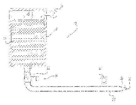
FIG. 1 is a side sectional view illustrating a preferred embodiment of
the present invention;
FIG. 2 is a view similar to FIG. 1 but illustrating the operation of the
invention following the initial opening of the valve;
FIG. 3 is a view similar to FIG. 2 and further illustrating the operation
of the preferred embodiment of the present invention; and
FIG. 4 is a graph illustrating the operation of the preferred embodiment
of the present invention.
Detailed Description of a Preferred
Embodiment of the Present Invention
With reference first to FIG. 1, a preferred embodiment of the water jet
10 of the present invention is there shown. and comprises a tank 1.2 which
forms a reservoir 14. The reservoir 14 is filled with a liquid, typically
water, to
the extent that an air pocket 16 is formed at the upper portion of the tank
12.
3

CA 02370449 2002-02-04
An elongated conduit 18 has one end 20 connected to the reservoir 14.
A valve 22 is fluidly connected in series between the end 20 of the conduit 18
and the reservoir 14. Preferably, this valve 22 is a gate valve and actuated
by
an actuator 24 between an open position and a closed position. In its closed
position (FIG. 1), the gate valve 22 prevents fluid flow from the reservoir 14
through the conduit while, conversely, in its open position (FIG. 2), the
valve
22 allows fluid to freely flow from the reservoir 14 and through the conduit
18.
Still referring to FIG. 1, a nozzle 26 is secured to the other end 28 of the
conduit 18. This nozzle 26 has an opening 30 which is smaller in cross-
sectional area than the cross-sectional area of the conduit 18. Preferably,
the
area of the nozzle opening 30 is in the range of one one-hundredth the cross-
sectional area of the conduit 18.
The conduit 18 extends in substantially a straight line from the valve 22
and to the nozzle 26 in order to minimize turbulence of the water flow through
the conduit 18. Additionally, an air bleed circuit 34 is fluidly connected to
the
interior of the conduit 18 either at or adjacent the nozzle 26. This air bleed
circuit 34 bleeds air from the conduit 18 during water flow through the
conduit
18. The air bleed circuit 34, furthermore, may include a vacuum pump which
actively evacuates the interior of the conduit 18 of air.
Still referring to FIG. 1, an air pressurization means 36, such as an air
pump, pressurizes the air pocket 16 in the tank 12 to a predetermined
pressure.
Preferably, this pressure is in the range of 30-300 psi. Additionally, the
cross-
sectional area of the tank 12 is preferably several times the cross-sectional
area
4

CA 02370449 2002-02-04
of the conduit 18 so that the effective pressure at the end 20 of the conduit
18 is
several times the pressure of the air pocket 16.
With reference now to FIGS. 1 and 2, when activation of the water jet is
desired, the valve 22 is moved from its closed position (FIG. 1) to its open
position (FIG. 2). In doing so, the water or other liquid contained within the
reservoir 14 flows downwardly through the valve 22 and into the conduit 18.
The flow of water through the conduit 18 will accelerate through the conduit
18
and thus.form a wall of water within the interior of the conduit 18 as shown
in
FIG. 2. Simultaneously as the water flows through the conduit 18, the air
bleed
circuit 34 removes air from the interior of the conduit so that the air within
the
conduit neither cushions the water flow through the conduit 18 nor creates
turbulence of the water flow through the conduit.
With reference now to FIG. 3, as the water flow through the conduit 18
and impacts the nozzle 26, the nozzle 26 reduces the water flow from the cross-
sectional area of the conduit 18 and to the reduced area of the nozzle opening
30. This in turn creates a high speed, high pressure water jet 40 at the
nozzle
opening 30.
With reference now to FIG. 4, a graph illustrating the pressure of the
water jet 40 as a function of time is illustrated. As shown in FIG. 4, as the
water flow through the conduit 18 initially hits the nozzle 26, an extremely
high pressure, e.g. 10,000 psi, is created at the water jet 40 as indicated at
point
42 in FIG. 4. Thereafter, the pressure of the water jet 40 diminishes until
the
cycle is completed.
5

CA 02370449 2002-02-04
One practical application for the water jet 10 of the present invention is
to clean industrial parts, such as engine blocks, of metal filings and other
debris. For example, assuming that the conduit 18 has an inside diameter of
,four inches and the nozzle opening 30 has a diameter of five-sixteenths of an
inch, a pressurization of about 150 psi in the air pocket 16 of the tank 12
causes
the water flow through the conduit 18 to reach a speed of about 55 miles per
hour in approximately six feet or straight section of the conduit 18. This
water
flow translates to a pressure of approximately 10,000 psi at the water jet 40.
Thus, when the water jet 10 is used to clean industrial parts, the high
initial
pressure from the water jet is sufficient to dislodge any shavings that may be
entrapped within passageways of the industrial parts, such as engine blocks,
and thereafter flush out any debris or metal shavings from the industrial
part.
From the foregoing, it can be seen that the present invention provides a
simple and yet highly effective water jet. Having described my invention,
however, many modifications thereto will become apparent to those skilled in
the art to which it pertains without deviation from the spirit of the
invention as
defined by the scope of the appended claims.
I claim:
6

Representative Drawing
A single figure which represents the drawing illustrating the invention.
Administrative Status

2024-08-01:As part of the Next Generation Patents (NGP) transition, the Canadian Patents Database (CPD) now contains a more detailed Event History, which replicates the Event Log of our new back-office solution.

Please note that "Inactive:" events refers to events no longer in use in our new back-office solution.

For a clearer understanding of the status of the application/patent presented on this page, the site Disclaimer , as well as the definitions for Patent , Event History , Maintenance Fee  and Payment History  should be consulted.

Event History

Description Date
Inactive: Expired (new Act pat) 2022-02-04
Common Representative Appointed 2019-10-30
Change of Address or Method of Correspondence Request Received 2018-01-12
Maintenance Request Received 2017-02-03
Inactive: Late MF processed 2014-02-07
Letter Sent 2014-02-04
Grant by Issuance 2011-01-04
Inactive: Cover page published 2011-01-03
Pre-grant 2010-10-05
Inactive: Final fee received 2010-10-05
Notice of Allowance is Issued 2010-04-15
Letter Sent 2010-04-15
Notice of Allowance is Issued 2010-04-15
Inactive: Approved for allowance (AFA) 2010-03-31
Amendment Received - Voluntary Amendment 2009-09-16
Inactive: S.30(2) Rules - Examiner requisition 2009-03-17
Letter Sent 2006-11-27
Request for Examination Received 2006-11-06
Request for Examination Requirements Determined Compliant 2006-11-06
All Requirements for Examination Determined Compliant 2006-11-06
Inactive: IPC from MCD 2006-03-12
Application Published (Open to Public Inspection) 2002-08-14
Inactive: Cover page published 2002-08-13
Inactive: First IPC assigned 2002-04-19
Inactive: Filing certificate - No RFE (English) 2002-03-05
Filing Requirements Determined Compliant 2002-03-05
Letter Sent 2002-03-05
Application Received - Regular National 2002-03-05

Abandonment History

There is no abandonment history.

Maintenance Fee

The last payment was received on 2010-01-28

Note : If the full payment has not been received on or before the date indicated, a further fee may be required which may be one of the following

  • the reinstatement fee;
  • the late payment fee; or
  • additional fee to reverse deemed expiry.

Please refer to the CIPO Patent Fees web page to see all current fee amounts.

Owners on Record

Note: Records showing the ownership history in alphabetical order.

Current Owners on Record
VALIANT CORPORATION
Past Owners on Record
ANDREW NOESTHEDEN
Past Owners that do not appear in the "Owners on Record" listing will appear in other documentation within the application.
Documents

To view selected files, please enter reCAPTCHA code :


To view images, click a link in the Document Description column. To download the documents, select one or more checkboxes in the first column and then click the "Download Selected in PDF format (Zip Archive)" or the "Download Selected as Single PDF" button.

List of published and non-published patent-specific documents on the CPD .

If you have any difficulty accessing content, you can call the Client Service Centre at 1-866-997-1936 or send them an e-mail at CIPO Client Service Centre.


Document
Description 
Date
(yyyy-mm-dd) 
Number of pages   Size of Image (KB) 
Representative drawing 2002-05-06 1 16
Description 2002-02-04 6 252
Claims 2002-02-04 2 41
Abstract 2002-02-04 1 24
Drawings 2002-02-04 2 77
Cover Page 2002-08-09 1 45
Description 2009-09-16 7 260
Claims 2009-09-16 3 69
Representative drawing 2010-12-06 1 18
Cover Page 2010-12-06 2 50
Courtesy - Certificate of registration (related document(s)) 2002-03-05 1 113
Filing Certificate (English) 2002-03-05 1 164
Reminder of maintenance fee due 2003-10-07 1 106
Reminder - Request for Examination 2006-10-05 1 116
Acknowledgement of Request for Examination 2006-11-27 1 178
Commissioner's Notice - Application Found Allowable 2010-04-15 1 166
Maintenance Fee Notice 2014-02-07 1 170
Late Payment Acknowledgement 2014-02-07 1 163
Fees 2004-01-14 1 30
Fees 2005-01-13 1 27
Fees 2006-01-19 1 26
Fees 2007-01-19 1 27
Fees 2008-01-10 1 27
Fees 2009-01-26 1 34
Fees 2010-01-28 1 34
Correspondence 2010-10-05 1 33
Fees 2011-02-04 1 33
Fees 2014-02-07 1 25
Maintenance fee payment 2017-02-03 2 52
Maintenance fee payment 2020-12-21 1 25