Note: Descriptions are shown in the official language in which they were submitted.
CA 02370516 2001-10-15
WO 00/62545 PCT/US00/08825
1
TITLE OF THE INVENTION
METHOD AND APPARATUS FOR USING RF DETECTOR AND DELAY CIRCUIT TO REDUCE NOISE
BUILDUP IN
RF RETURN SYSTEMS
FIELD OF THE INVENTION
The present invention relates to the field of cable
television systems. More particularly, the present
invention relates to the field of minimizing noise
buildup in RF return systems by which the set-top
terminals of individual cable subscribers communicate
with the cable signal headend. The RF return systems
involved with the present invention may be either wired
or wireless.
BACKGROUND OF THE INVENTION
In a cable television system, the cable television
service provider establishes a signal headend from
which television signals are distributed over the cable
system to the population of subscribers. Typically,
each subscriber receives a set-top terminal that is
connected between an outlet to the cable system and the
subscriber's television set. The set-top terminal
allows the subscriber's television to make use of the
cable television signal.
In some instances, the set-top terminal also sends
signals to communicate with the headend. These signals
are typically radio frequency (RF) signals. Thus, the
system by which the set-top terminal communicates with
the headend is known as an RF return system. The
return signals are generated by the set-top terminal
and are sent to the headend via an RF transmitter in a
wireless return system, or over an RF wire-line link in
a wired return system.
CA 02370516 2001-10-15
WO 00/62545 PCT/US00/08825
2
A problem arises in RF return systems due to the
buildup of unwanted signal noise. The active
electronics
of the set-top terminals and, in wireless return
systems, the RF transmitters, generate a small amount
of random noise or other spurious signals that
propagate upstream over the RF return system. This
unwanted signal noise is generated even if the RF
transmitter is inactive, i.e., not transmitting a
signal. Spurious noise can also be created in wired
return systems by signal leakage or interference caused
by over-the-air short wave or two-way radio or other
signal broadcasts.
The amount of noise generated by or through any one
set-top terminal may be almost negligible, particularly
with careful design, shielding and construction.
However, the buildup of noise from the totality of set-
top terminals of all the subscribers to the cable
system creates a substantial problem in the RF return
system.
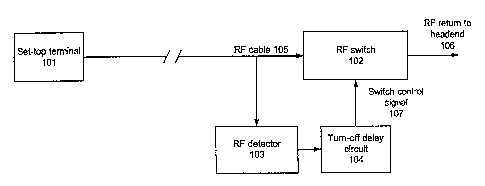
A conventional means of addressing this problem is
illustrated in Fig. 3. As shown in Fig. 3, a set-top
terminal (101) is provided for each subscriber and
connected between the cable system and the subscriber's
television set (not shown). The set-top terminal (101)
is connected by an RF signal cable (105) to the RF
return system (106).
In order to prevent the random noise generated by
the set-top terminal (101) from being introduced to the
RF return system (106), an RF switch (102) is
interposed along the cable (105) between the set-top
terminal (101) and the RF return system (106). The
switch (102) is opened when the set-top terminal (101)
is not signaling the headend thereby preventing any
CA 02370516 2001-10-15
WO 00/62545 PCT/US00/08825
3
noise generated from propagating into the RF return
system (106).
The set-top terminal (101) is also provided with a
separate wire connection (301) for controlling the
switch (102). When the set-top terminal (101) needs tc
signal the headend, the terminal (101) generates a
switch control
signal on this connection (301) that signals the switch
(102) to close. The set-top terminal is then linked
through the switch (102) to the RF return system (106).
When the set-top terminal (101) is finished signaling
the headend, the switch (102) opens to again prevent
noise from the terminal (101) from reaching the RF
return system (106).
Fig. 4 illustrates a solution to noise buildup
using the same principles in a wireless cable system.
As shown in Fig. 4, the set-top terminal (101) is
connected via cable (105) with a transverter (201).
The transverter (201) is an RF transmitter for
wirelessly signaling the headend as an RF return system
( 116 ) .
To prevent unwanted noise from being transmitted as
part of the RF return system (116), the set-top
terminal (101) has a separate wired connection (401)
over which an ON/OFF signal is sent to the transverter
(201) to shut the transverter (201) down when the set-
top terminal (101) is not using the RF return system
(116) to signal the head end.
While these arrangements limit the noise buildup in
the RF return system, they also raise several problems.
It must be noted that the transverter (201) (Fig. 4),
or the RF switch (102) (Fig. 3), is typically mounted
outside the subscriber's house remote from the set-top
terminal (101). Thus, the systems of Figs. 3 and 4
CA 02370516 2001-10-15
WO 00/62545 PCT/US00/08825
4
require additional wiring between the set-top terminal
(101) and the components exterior to the subscriber's
home in order to provide the control connections (301)
and (401). Additionally, there is a delay required to
signal the switch (102) or the transverter (201) over
the connections (301) or (401), respectively, before
the set-top terminal can begin using the RF return
system (106) or (116).
Consequently, there is need in the art for a method
and apparatus of preventing unwanted noise buildup in
the RF return system of a cable television system that
does not require additional wiring between the set-top
terminal and the components exterior to a subscriber's
house. There is a further need in the art for a method
and apparatus of regulating the connection between a
set-top terminal and an RF return system that avoids
unnecessary delay in providing access to the RF return
system when needed.
SUMMARY OF THE INVENTION
It is an object of the present invention to meet
the above-described needs and others. Specifically, it
is an object of the present invention to provide a
method and apparatus of preventing unwanted noise
buildup in the RF return system of a cable television
system that does not require additional wiring between
the set-top terminal and the components exterior to a
subscriber's house. It is a further object of the
present invention to provide a method and apparatus of
regulating the connection between a set-top terminal
and an RF return system that avoids unnecessary delay
in providing access to the RF return system when
needed.
CA 02370516 2001-10-15
WO 00/62545 PCT/US00/08825
Additional objects, advantages and novel features
of the invention will be set forth in the description
which follows or may be learned by those skilled in the
art through reading these materials or practicing the
5 invention. The objects and advantages of the invention
may be achieved through the means recited in the
attached claims.
To achieve these stated and other objects, the
present invention may be embodied and described as an
apparatus for minimizing noise buildup in a signal
return system of
a cable television system through which a set-top
terminal signals a cable system headend. In a
preferred embodiment, the apparatus of the present
invention includes: a signal detector connected to the
output of a set-top terminal; and a selective link
between the set-top terminal and the signal return
system. The selective link is activated by the signal
detector so as to operatively connect the set-top
terminal with the signal return system when the signal
detector detects a signal output by the set-top
terminal. A delay circuit is preferably used for
delaying deactivation of the selective link for a
predetermined period of time after the signal detector
no longer detects the signal output by the set-top
terminal.
Where the signal return system is a wireline
system, the selective link includes a switch for
selectively coupling the set-top terminal with the
signal return system. The signal detector closes the
switch so as to connect the set-top terminal to the
signal return system when the signal detector detects a
signal output by the set-top terminal. The signal
detector also signals the switch to open when the
CA 02370516 2001-10-15
WO 00/62545 PCT/US00/08825
6
output signal from the set-top terminal is no longer
detected.
If the delay circuit is used, the delay circuit
maintains the switch in a closed state for a
predetermined period of time after the signal detector
stops detecting the signal output by the set-top
terminal. This is particularly important if the output
signal from the set-top terminal is time division
multiplexed and comprises a series of spaced signal
bursts.
If the signal return system is a wireless system,
the selective link preferably includes a transverter
for transmitting signals from the set-top terminal to
the headend. The signal detector turns the transverter
on when the signal detector detects a signal output by
the
set-top terminal. The signal detector also signals the
transverter to deactivate when the output signal from
the set-top terminal is no longer detected.
If the delay circuit is used, the delay circuit
maintains the transverter in an on state for a
predetermined period of time after the signal detector
stops detecting the signal output by the set-top
terminal. Again, this is particularly useful if the
output signal from the set-top terminal is time
division multiplexed.
The present invention also encompasses a method for
minimizing noise buildup in a signal return system of a
cable television system through which a set-top
terminal signals a cable system headend. The method
includes activating a selective link between the set-
top terminal and the signal return system in response
to detection of a signal output by the set-top
terminal. Preferably, the method also includes
CA 02370516 2001-10-15
WO 00/62545 PCT/US00/08825
7
delaying deactivation of the selective link for a
predetermined period of time after the signal output by
the set-top terminal ceases.
BRIEF DESCRIPTION OF THE DRAWINGS
The accompanying drawings illustrate the present
invention and are a part of the specification.
Together with the following description, the drawings
demonstrate and explain the principles of the present
invention.
Fig. 1 is a block diagram of a device for
preventing unwanted noise in a wired RF return system
of a cable television network according to the present
invention.
Fig. 2 is a block diagram of a device for
preventing unwanted noise in a wireless RF return
system of a cable television network according to the
present invention.
Fig. 3 is a block diagram of a conventional device
for preventing unwanted noise in a wired RF return
system of a cable television network.
Fig. 4 is a block diagram of a conventional device
for preventing unwanted noise in a wireless RF return
system of a cable television network.
DETAILED DESCRIPTION OF THE PREFERRED EMBODIMENTS
Using the drawings, the preferred embodiments of
the present invention will now be explained. In the
drawings, identical numbers indicate identical system
elements.
Fig. 1 illustrates the principles of the present
invention as applied to a wired cable television
network with a wired RF return system (106). As shown
in Fig. 1, a set-top terminal (101) is connected via a
CA 02370516 2001-10-15
WO 00/62545 PCT/US00/08825
8
cable (105) to an RF return system (106). An RF switch
(102) is employed between the set-top terminal (101)
and the RF return system (106) to prevent spurious
noise from the set-top terminal (101) from entering the
RF return system (106) when the set-top terminal (101)
is not using the RF return system (106).
In contrast to the prior systems described above,
the set-top terminal (101) has no direct control over
the open/closed status of the switch (102). Rather, an
RF signal detector (103) is connected to the cable
(105). When the detector (103) detects an RF signal
from the set-top terminal (101), it signals the switch
(102) to close, thereby connecting the set-top terminal
(101) to the RF return system (106). This arrangement
eliminates the need for additional wiring between the
set-top terminal (101) and the RF switch (102) which is
usually located on the exterior of a subscriber's house
remote from the set-top terminal (101).
As shown in Fig. 1, the link between the RF
detector (103) and the RF switch (102) also includes a
delay circuit (104). A typical RF return system (106)
uses time-based multiplexing to accommodate the large
number of
subscriber set-top terminals which may be needed to use
the RF return system (106) to signal the headend.
Therefore, a signal from the set-top terminal (101) to
the RF return system (106) may actually be transmitted
as a number of brief transmissions using time division
multiple access (TDMA).
This can create a problem for the RF detector (103)
which would try to rapidly switch the RF switch (102)
on and off to accommodate each of the brief spring of
transmissions in the string of transmission bursts from
the set-top terminal (101). Each transmission burst
CA 02370516 2001-10-15
WO 00/62545 PCT/US00/08825
9
may experience a delay during which the detector (103)
activates the switch (102).
This problem is avoided, however, by adding the
turn-off delay circuit (104) between the detector (103)
and the switch (102). The turn-off delay circuit (104)
keeps the switch (102) closed, i.e. keeps the set-top
terminal (101) connected to the RF return system (106),
for a predetermined period of time after the RF
detector (103) has ceased detecting an RF signal on the
cable (105) .
The predetermined period during which the turn-off
delay circuit (104) maintains the link between the set-
top terminal (101) and the RF return system (106)
should be minimized. For example, if the transmission
bursts in the TDMA scheme being used are separated by
10 seconds, the delay circuit (104) will hold the
switch (102) closed for 10 seconds or more after the RF
detector (103) ceases to detect an RF signal on the
cable (105). In this manner, only the first
transmission burst may experience a delay in the
activation of the switch (102). All the transmission
bursts in the signal thereafter will find the switch
(102) held closed by the turn-off delay circuit (104).
Fig. 2 illustrates the principles of the present
invention as applied to a cable system with a wireless
RF return system (116). As shown in Fig. 2, a set-top
terminal (101) is connected via a cable (105) to a
wireless RF return system (116). A transverter (201)
is used to wirelessly transmit signals from the
terminal (101) over the RF return system (116). To
prevent spurious noise from the transverter (201) from
propagating over the RF return system (116), it is
desired to turn off the transverter (201) when the set-
CA 02370516 2001-10-15
WO 00/62545 PCT/US00/08825
top terminal (101) is not using the RF return system
(116) .
In contrast to the prior systems described above,
the set-top terminal (101) has no direct control over
5 the ON/OFF status of the transverter (201). Rather, an
RF signal detector (103) is connected to the cable
(105). When the detector (103) detects an RF signal
from the set-top terminal (101), it turns on the
transverter (201), thereby enabling transmissions from
10 the set-top terminal (101) to the RF return system
(116). This arrangement eliminates the need for
additional wiring between the set-top terminal (101)
and the transverter (201) which is typically mounted on
the exterior of a subscriber's house remote from the
set-top terminal (101).
As shown in Fig. 2, the link between the RF
detector (103) and the transverter (201) also includes
a delay circuit (104). As before, the turn-off delay
circuit (104) keeps the transverter (201) turned on for
a predetermined period of time after the RF detector
(103) has ceased detecting an RF signal on the cable
(105) .
The predetermined period during which the turn-off
delay circuit (104) maintains the transverter (201) in
the "on" state should be minimized. As in the
preceding example, if the transmission bursts in the
TDMA scheme being used are separated by 10 seconds, the
delay circuit
(104) will keep the transverter (201) on for 10 seconds
or more after the RF detector (103) ceases to detect an
RF signal on the cable (105). In this manner, only the
first transmission burst may experience a delay in the
activation of the transverter (201). All the
CA 02370516 2001-10-15
WO 00/62545 PCT/US00/08825
11
transmission bursts in the signal thereafter will find
the transverter (201) turned on.
Consequently, the present invention allows optimal
control of the RF switch (102) or transverter (201) so
as to minimize spurious noise in the return system (106
or 116) without a control connection between the set
top terminal (101) and the return system (106 or 116).
Moreover, the delay circuit (104) avoids the problem
of delay in activating the selective link between the
set-top terminal (101) and the return system (106 or
116). Thus, communication from the set-top terminal
(101) to the headend is made swift, efficient and free
of noise .
The preceding description has been presented only
to illustrate and describe the invention. It is not
intended to be exhaustive or to limit the invention to
any precise form disclosed. Many modifications and
variations are possible in light of the above teaching.
The preferred embodiment was chosen and described
in order to best explain the principles of the
invention and its practical application. The preceding
description is intended to enable others skilled in the
art to best utilize the invention in various
embodiments and with various modifications as are
suited to the particular use contemplated. It is
intended that the scope of the invention be defined by
the following claims.