Note: Descriptions are shown in the official language in which they were submitted.
CA 02370806 2001-10-22
- 1 -
Device for Atomizing Liquid Melts
The invention relates to a device for atomizing liquid melts,
in particular oxidic slags or glasses, including a slag
tundish and an outlet opening into which a lance is immersed
to inject gases or vapor while forming an annular gap.
A number of proposals have been known for the atomization and
granulation of liquid slags, in which liquid slags are
discharged from a slag tundish into a cooling chamber via an
outlet opening either in a free jet or are subsequently fed
with vapor and/or cold water while still in the cooling
chamber so as to enable rapid and intensive glassy
solidification. In this context, also high-pressure cold water
was proposed as a propellant jet in addition to vapor, inert
gases being, of course, also suitable to eject liquid melts.
If vapor is used as a propellant in such a process, it may
happen with an.accordingly intensive cooling that a negative
pressure will form in the consecutively arranged cooling
chamber by condensation. If cold water is used, the contact
with liquid melts will cause. rapid evaporation such that an
overpressure may optionally build up there. As a result,
different pressure conditions will prevail, particularly in
the region of the outlet openings, whereby a negative pressure
may form just as much as an overpressure in the region of the
nozzle gap. In order to ensure the appropriate atomization
adapted to the respective conditions and, above all, safeguard
an accordingly fine atomization, it is, therefore, necessary
to adapt the nozzle geometry to the respective conditions.
In the configurations known so far, the lance used to inject
gases or vapor was arranged either above the liquid melt level
and thus subjected to less wear, whereby the ejection
characteristic naturally was highly dependent on the slag bath
height or melt bath height, respectively. In configurations in
which the lance is immersed in the liquid melt, accordingly
high-temperature-resistant materials must, of course, be
employed, whereby the observance of a defined jet geometry and
a defined atomization is rendered difficult because
CA 02370806 2001-10-22
- 2 -
solidification in the region of the outlet opening will bring
about changes in the gap geometry and alterations in the grain
size distribution of the atomized droplets.
The invention aims to provide a device of the initially
defined kind, by which it is feasible in a simple manner to
counteract the adhesion of a slag fleece due to solidification
in the region of the outlet opening and by which it is
feasible, at the same time, to adapt the desired jet
parameters to the respectively prevailing conditions. To solve
this object, the device according to the invention essentially
consists in that the lance is comprised of two coaxial tubes
which are separately displaceable in the axial direction and
fixable in their respective axially displaced positions. Due
to the fact that two coaxial tubes are provided, the inlet gap
width for the liquid melt may be adjusted by means of the
external tube by a relative displacement of these two tubes,
whereas the desired jet parameters may be adapted to the.
respective preconditions such as, for instance, pressure or
type of propellant jet medium by a suitable adjustment of the
internal tube. In'addition, it is feasible with such a lance
design comprising two coaxial tubes to use different materials
and provide, for instance, a sleeve or external tube of a
high-temperature-resistant ceramic material or cost-effe.ctive
graphite, while making the internal tube of the lance of an
accordingly high-temperature-resistant steel or, likewise, of
a ceramic material, being protected by the sleeve against
excessive corrosive or thermal attacks by the melt. By using a
sleeve as a wear part, it is feasible, in the main, to
considerably reduce the operating costs of such a device and,
at the same time, adjust the parameters for the desired
droplet formation or jet formation within wide limits.
The use of graphite as a material for the sleeve is, of
course, suitable only if carbon is insoluble in the melt to be
atomized. This holds for melts that contain neither metals nor
iron or chromium oxides. When using graphite as a material for
the external tube, this will constitute a particularly cost-
effective wear part which, at the same time, offers the
CA 02370806 2001-10-22
- 3 -
opportunity to effectively counteract the closing up of the
outlet opening.
Advantageously, the configuration according to the invention
is devised such that the outlet opening in the form of a
nozzle block and the external tube or sleeve are made of an
electrically conductive material, in particular graphite,
whereby, if also the nozzle block is made of an electrically
conductive material, electric heating may be effected in a
simple manner, for instance, by the formation of an electric
arc between the sleeve and the nozzle block in the region of
the inlet opening and the propellant jet feed so as to enable
the assurance of a constant nozzle geometry during operation.
When providing such heating in the region of the nozzle gap it
is still feasible to make use of another important advantage
of the configuration according to the invention. After all, it
basically appl.ies that the droplets or respective solidifying
particles will become finer the higher the vapor temperature,
this being due, inter alia, to an accordingly enhanced
rheology of the droplets. However, high final vapor
temperatures usually call for an accordingly cumbersome vapor
. generation and an accordingly demanding supply of high=
temperature vapor to the lance. Due to the fact that the final
heating or final superheating of vapor may be effected, for
instance, by an electric arc, superheating of the vapor to a
maximum of 1600 C may be reached by substantially lower vapor
temperatures and, for instance, vapor temperatures of about
700 C at a maximum vapor pressure of 10 bars. The generation
of vapor is, thus, accordingly more cost-effective, the
temperature load on the vapor lance, thus, being strongly
reduced. The superheating of "cold vapor" in the nozzle
region, inter alia, will cause the lance itself to be relieved
from vapor pressure, because in that region the pressure has
already been converted into jet speed, the jet tube thus being
subjected to a substantially lower thermal load.
According to another preferred embodiment, the central tube of
the lance is made of a ceramic material or high-temperature-
resistant steel, whereby the requirements for a precise jet
CA 02370806 2001-10-22
- 4 -
geometry may be more readily observed. While thermal
deformation and optionally even the melting off of the lance
mouth has to be taken into account in conventional lances made
of steel, it is feasible, by using a sleeve made of an
accordingly temperature-resistant material, to keep the direct
action of the slag away from the mouth of the central tube or
internal tube such that the constancy of the jet geometry may
be maintained over an extended period of time.
In a particularly advantageous manner, the configuration is
devised such that the nozzle block comprises a conically
designed inlet opening and an oppositely conical outlet
opening diverging towards the mouth, whereby it is safeguarded
that the inlet gap and the essential atomization parameters
may be adjusted in a simple manner by appropriate axial
displacement.
As already pointed out in the beginning, it is particularly
advantageous if the geometry of the outlet opening is kept
free of influences such as, for instance, closing up by
solidification, and it, therefore, corresponds to a preferred
embodiment that the nozzle block and the external tube or
sleeve are connected with a power source to provide electrical
heating in the region of the nozzle block.
If a significant rise in the atomization fineness is to be
observed upon adjustment of the essential atomization
parameters, the size of the atomized melt droplets may be
reduced even further in that, as in correspondence with a
preferred configuration, at least one annular nozzle is
arranged coaxial with the outlet opening in a spraying chamber
connected to the slag tundish, the axes of the nozzle outlet
openings preferably being oriented substantially parallel with
the axis of the lance, or in a diverging manner. In the region
of the sprayed melt droplets emerging from the tundish through
the outlet opening, thread formation cannot be prevented,
which is due primarily to the elevated surface tension of the
solidifying melt droplets. By arranging an annular nozzle
within the spraying chamber, additional vapor and/or hot gases
CA 02370806 2007-11-23
-5-
such as, e.g., combustion offgases may be ejected within the
spraying chamber, heating the solidifying melt droplets up
again upon contact therewith and, thus, enabling a decrease of
the surface tension and a further reduction of the size of the
droplets. Vapor or hot gases preferably are ejected in
parallel with the axis of the lance, whereby a vapor or hot-
gas jacket surrounding the outlet opening of the tundish is
formed, which delimits the space available to the expansion of
the sprayed melt droplets. The vapor or hot gas ejected from
the annular nozzle will seize, in particular, the melt
droplets present in the border region of the melt droplet jet
emerging from the tundish, which were cooled most and,
therefore, are the first to tend to thread formation.
Advantageously, the configuration, therefore, is devised such
that the annular nozzle comprises a duct for supplying vapor
and/or hot gases particularly at a temperature exceeding the
temperature of the emerging slag jet.
According to an aspect of the invention there is provided a
device for atomizing liquid oxidic slag or glass melts, the
device including a tundish into which a lance is immersed
and an outlet opening from said tundish for injecting gases
or vapors while forming an annular gap in said opening for
passage of the melts, wherein the lance is comprised of
inner and outer coaxial tubes which are separately
displaceable in an axial direction and fixable in
respective axially displaced positions, said inner tube
injecting said gases or vapor and the position of said
outer tube relative to the opening defining the size of
said annular gap.
In the following, the invention will be explained in more
detail by way of an exemplary embodiment schematically
illustrated in the drawing. Therein, Fig. 1 is a partial view
of a slag tundish including an outlet opening; and Fig. 2
depicts a slag tundish comprising a spraying chamber connected
thereto.
CA 02370806 2007-11-23
-5a-
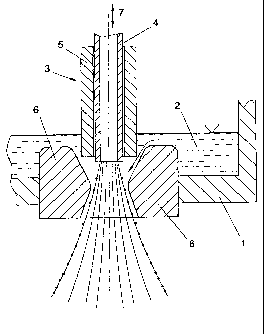
In Fig. 1, the bottom and a'side wall of a slag tundish are
denoted by 1. In the tundish is contained a molten slag 2 in
which a lance 3 is immersed. The lance 3 is comprised of an
internal tube 4 made of high-temperature-resistant steel and
an external tube or sleeve 5 made of graphite. In the bottom
of the slag tundish is arranged a nozzle block 6 which itself
may again be made of graphite, wherein, when using graphite
for the material of the sleeve 5 and the nozzle block 6, it
merely has to be taken into account that the melt 2 will not
contain any materials in which carbon is soluble. This holds,
in particular, if the melt is no iron melt and if the melt
contains neither iron oxides.nor chromium oxides.
CA 02370806 2001-10-22
- 6 -
The two structural components of the lance 3, i.e., the
internal tube 4 and the sleeve 5 may each be separately
adjusted in height in the sense of double arrow 7. A
displacement of the external sleeve 5, on the one hand,
defines the width of the inlet gap for liquid melts. On the
other hand, when using graphite for the material of the sleeve
5 and the nozzle block 6, a stable electric arc may build up
between these two structural components acting as electrodes,
so as to prevent the geometry and the definedly adjusted gap
width from being affected by the solidification procedures. By
displacing the central tube 4 of the lance 3, the geometry of
the jet may be adjusted within wide limits and adapted to the
respective propellant. In the main, it is feasible with such a
lance comprised of two coaxial tubes to not only control
thermal problems and corrosion problems, but also adjust a
defined jet geometry capable of being maintained over an
extended period of operation.
Fig. 2 again depicts a slag tundish containing molten slag 2.
An internal tube 4 of a lance 3, which is immersed in the
slag, is again apparent, said internal tube 4 being surrounded
by a safety tube 5. In the instant case, a spraying chamber 8
is connected to the slag tundish 1, whereby an annular nozzle
ring 10 is arranged concentrically with the axis 9 of the
lance. The vapor or hot-gas stream emerging from the annular
nozzle ring 10 is oriented substantially parallel with the
axis 9 of the lance 3, getting into contact with the outer
region of the atomized melt droplets. Thereby, the melt
droplets, which have already cooled down at least partially,
are heated up again and, favored by the thus lowered surface
tension, are further reduced and atomized. This enables an
even finer atomization of the melt.