Language selection

Search

Patent 2370811 Summary

Third-party information liability

Some of the information on this Web page has been provided by external sources. The Government of Canada is not responsible for the accuracy, reliability or currency of the information supplied by external sources. Users wishing to rely upon this information should consult directly with the source of the information. Content provided by external sources is not subject to official languages, privacy and accessibility requirements.

Claims and Abstract availability

Any discrepancies in the text and image of the Claims and Abstract are due to differing posting times. Text of the Claims and Abstract are posted:

  • At the time the application is open to public inspection;
  • At the time of issue of the patent (grant).
(12) Patent Application: (11) CA 2370811
(54) English Title: SEAT FRAME STRUCTURE AND METHOD FOR FORMING
(54) French Title: STRUCTURE DE CHASSIS DE SIEGE ET METHODE DE FORMAGE
Status: Dead
Bibliographic Data
(51) International Patent Classification (IPC):
  • B60N 2/68 (2006.01)
  • B21D 19/08 (2006.01)
  • B21D 28/28 (2006.01)
  • B21D 39/00 (2006.01)
  • B21D 39/04 (2006.01)
  • B21D 39/06 (2006.01)
(72) Inventors :
  • FRENKE, BILL (Canada)
  • MCWHINNIE, JOHN (Canada)
(73) Owners :
  • TRITON TUBULAR COMPONENTS CORP. (Canada)
(71) Applicants :
  • JRM TUBE INC. (Canada)
(74) Agent: GOWLING LAFLEUR HENDERSON LLP
(74) Associate agent:
(45) Issued:
(22) Filed Date: 2002-02-06
(41) Open to Public Inspection: 2003-08-06
Availability of licence: N/A
(25) Language of filing: English

Patent Cooperation Treaty (PCT): No

(30) Application Priority Data: None

Abstracts

English Abstract


The present invention provides a method of forming a transversely
extending passage through a tubular seat frame for receiving a headrest guide
tube
and includes the steps of:
(i) forming first and second diametrically opposed axially aligned
openings through the tubing;
(ii) flowing metal from around the first opening through the tube and
through the second opening while expanding the first opening to form at
least part of an inner wall of the passage;
(iii) flowing metal from around the second opening outwardly from the
tube while expanding the second opening to form an outer wall of the
passage extending about the inner wall.


Claims

Note: Claims are shown in the official language in which they were submitted.


-11-

Claims:

1. A method of forming a transversely extending passage through a tubular
seat frame member of ductile metal tubing for receiving a headrest guide
tube; said method comprising the steps of:
(i) forming first and second diametrically opposed axially aligned
openings through said tubing;
(ii) flowing metal from around said first opening through said tube and
through said second opening while expanding said first opening to form at
least part of an inner wall of said passage;
(iii) flowing metal from around said second opening outwardly from said
tube while expanding said second opening to form an outer wall of said
passage extending about said inner wall.

2. A method of securing a headrest guide tube to a tubular seat frame member
of ductile metal tubing, said method comprising the steps of:
(i) forming first and second diametrically opposed axially aligned
openings through said tubular member;
(ii) flowing metal from around said first opening through said tubular
seat frame member and through said second opening while expanding said
first opening to initiate a passage extending through said tubular member;
(iii) flowing metal from around said second opening outwardly from said
tubular seat frame member while expanding said second opening to receive
said metal from around said first opening and form an upstanding wall
about said passage, said passage having an entrance adjacent said tubular
seat frame member and an exit distal said tubular seat frame member;


-12-

(iv) inserting said guide tube through said passage;
(v) deforming said guide tube to form a first detent on said guide tube
for limiting displacement of said guide tube in a first direction into said
entrance; and
(vi) forming a second detent by deforming at least one of said upstanding
wall and said guide tube to, in conjunction with said first detent, fixedly
secure said guide tube to said tubular seat frame member.

3. The method of claim 2 wherein:
said forming in step (i) is by punching;
said first detent is a first bead; and,
said second detent is a second bead on said guide tube.

4. The method of claim 2 wherein:
said forming in step (i) is carried out by punching;
said first detent is a bead; and
said second detent is formed by clenching said upstanding wall about said
guide tube.

5. The method of claims 2, 3 or 4 wherein:
step (iv) is carried out before step (v).

6. The method of claims 2, 3 or 4 wherein:
step (v) is carried out before step (iv).

7. The method of claim 4 wherein:


-13-

a portion of said upstanding wall is caused to flow into said guide tube to
secure said guide tube against rotational movement relative to said seat
frame.

8. The method of claim 7 including the further step of:
forming a recess in said guide tube prior to said clenching to receive said
portion of said upstanding wall.

9. A method of forming a headrest guide tube mounting passage in a tubular
seat frame member of ductile metal tubing, said method comprising the
steps of:
(i) punching first and second axially aligned holes through
diametrically opposite locations along said tubing;
(ii) placing said tubing in an extruding die-set with a core of said die-set
aligned with said first hole and a cavity of said die-set aligned with said
second hole;
(iii) urging said core toward said cavity to cause metal surrounding said
first and second holes to flow into said cavity while simultaneously
enlarging said first and second holes to form said guide tube passage.

10. A method for securing a headrest guide tube to a tubular seat frame member
of ductile metal, said method comprising the steps of:
(i) punching first and second axially aligned holes through
diametrically opposite locations along said tubular seat frame member;
(ii) placing said tubular seat frame member in an extruding die-set with
a core of said die-set aligned with said first hole and a cavity of said die-
set
aligned with said second hole;


-14-

(iii) urging said core toward said cavity to cause metal surrounding said
first and second holes to flow into said cavity while simultaneously
enlarging said first and second holes to form a guide tube passage having
an entrance adjacent said tubular seat frame member and an exit distal said
tubular seat frame member;
(iv) inserting said guide tube through said passage;
(v) deforming said guide tube to form a first detent on said guide tube
for limiting displacement of said guide tube in a first direction into said
entrance; and,
(vi) forming a second detent by deforming at least one of said upstanding
wall and said guide tube to, in conjunction with said first detent, fixedly
secure said guide tube to said tubular seat frame member.

11. The method of claim 10 wherein:
said first detent is a first bead; and,
said second detent is a second bead on said guide tube.

12. The method of claim 10 wherein:
said first detent is a bead; and,
said second detent is formed by clenching said upstanding wall about said
guide tube.

13. The method of claims 10, 11 or 12 wherein:
step (iv) is carried out before step (v).

14. The method of claims 10, 11 or 12 wherein:


-15-

step (v) is carried out before step (iv).

15. The method of claim 12 wherein a portion of said upstanding wall is caused
to flow into said guide tube to secure said guide tube against rotational
movement relative to said seat frame.

16. The method of claim 15 including the further step of:
forming a recess in said guide tube prior to said clenching to receive said
portion of said upstanding wall.

17. The method of claim 11 further including the step of:
forming serrations about said entrance into which a portion of said first
bead may be caused to flow.

18. The method of claim 1, 2, 3, 4, 7, 8, 9, 10, 11, 12, 15, 16 or 17 further
including the step of:
flattening the tubular seat frame member in the region wherein said first
and second openings are to be formed in step (ii), prior to performing step
(ii).

19. A tubular seat frame member comprising:
a run of ductile metal tubing having at least two headrest guide tube
mounting passages extending transversely therethrough;
each said mounting passage having an upstanding wall encircling said
passage and extending outwardly from one side of said tubular seat frame
member;
said passage having a first end proximal said run of tubing and a second
end distal said run of tubing.


-16-

20. The tubular seat frame member of claim 19 wherein:
said upstanding wall further comprises nested inner and outer wall
members extending from respectively opposite sides of said tubular seat
frame member.

21. The tubular seat frame member of claims 19 or 20 further comprising:
a respective headrest guide tube extending through each said passage;
each said headrest guide tube being secured to said seat frame by first
locating means at said first end and second locating means at second end.

22. The tubular seat from member of claim 19 wherein:
said first and second locating means are respective beads formed in said
guide tube.

23. The tubular seat frame member of claim 19 wherein:
said first locating means is a bead formed in said headrest guide tube; and,
said second locating means is a clenching of said upstanding wall about
said headrest guide tube.

24. The tubular seat frame member of claim 19 or 20 wherein:
said headrest guide tube and said run of tubing having inter-engaging
projections and recesses formed therein to restrain said guide tube from
rotation relative to said run of tubing.

25. The tubular seat frame member of claim 19, 20, 22 or 23 wherein:
said run of tubing has a flattened region in the vicinity of said passage.


-17-

26. The tubular seat frame of claim 21 wherein:
said run of tubing has a flattened region in the vicinity of said passage.

27. The tubular seat frame of claim 24 wherein:
said run of tubing has a flattened region in the vicinity of said passage.

Description

Note: Descriptions are shown in the official language in which they were submitted.


CA 02370811 2002-02-06
n J.
TITLE: SEAT FRAME S~'RUCTURE AND METHOD FOR FORMING
FIELD OF THE INVENTION
This invention relates generally to seat frames and more specifically to the
joining of a headrest guide tube to a tubular seat frame such as for
automotive
application.
BACKGROUND OF THE INVENTION
One method of providing support for the seat back of an automotive seat is
to provide a frame of metal tubing which runs generally contiguous to the
perimeter of the seat. As automotive seats require headrests for passenger
safety,
provision is required to secure the headrest to the seat frame.
One manner of mounting a headrest is to provide the headrest with two
generally parallel downwardly depending mounting posts which are slidable
relative to corresponding guide tubes mounted to the seat frame. The headrest
guide tubes generally receive an insert which may be a polymeric sleeve to
provide smooth motion. A detent means may also be provided which acts between
the headrest guide tube and the headrest mounting posts to maintain position
of the
headrest at a desired height.
Traditionally the headrest guide tubes were secured to the seat frame tube
by welding. This proved undesirable principally because of the difficulty in
assuring close dimensional tolerances and good alignment in any cost effective
mass production process.
More recently, as evidenced by U.S. Patent No. 5,759,499 to Dudash and
U.S. Patent No. 6,035,516 to Petersen securement of a headrest guide tube to a
seat frame tube by forming beads on the headrest guide tube has been
introduced.

CA 02370811 2002-02-06
c
-2-
The securement generally involves forming a web by flattening the seat frame
tube
and punching a hole through the web in the seat frame tube to receive the
headrest
guide tube. A first radially outwardly extending bead is formed on the tube
and the
beaded tube is inserted into the hole using the bead to position the headrest
guide
S tube. A second bead is then formed on the headrest guide tube on the
opposite side
of the flattened seat frame tube to capture the seat frame tube between the
two
beads.
A significant drawback to the above beading method is the loss in rigidity
associated both with flattening of the seat frame tube and the loss of metal
removed in punching a hole of significant diameter relative to the amount of
material present in the seat frame tube. In an effort to recover some of the
lost
rigidity Petersen teaches forming upstanding flanges on either side of the
flattened
area. Nevertheless, the amount of rigidity provided by the flanges is not
significant
compared to the rigidity of the seat frame tube before punching.
1 S Another drawback to the process of the foregoing patents is the
possibility
of the headrest guide tube rotating relative to the seat frame tube. This is
undesirable as the positional relationship between the headrest guide tube and
the
seat frame tube should be maintained in order to maintain orientation of the
detent
means.
It is an object of the present invention to provide a method whereby a
headrest guide tube opening may be formed in a seat ube with only minimal
removal of metal from the seat frame tube.
SUMMARY OF THE INVENTION
A method of forming a transversely extending passage through a tubular
seat frame for receiving a headrest guide tube comprises the steps of:

CA 02370811 2002-02-06
_3_
forming first and second diametrically opposed axially aligned openings
through said tubing;
(ii) flowing metal from around said first opening through said tube and
through said second opening while expanding said first opening to form at
least part of an inner wall of said passage;
(iii) flowing metal from around said second opening outwardly from said
tube while expanding said second opening to form an outer wall of said
passage extending about said inner wall.
A method of securing a headrest guide tube to a tubular seat frame member
of ductile metal comprises the steps of
(i) forming first and second diametrically opposed axially aligned
openings through said tubular member;
(ii) flowing metal from around said first opening through said tubular
seat frame member and through said second opening while expanding said
first opening to initiate a passage extending through said tubular member;
(iii) flowing metal from around said second opening outwardly from said
tubular seat frame member while expanding said second opening to receive
said metal from around said first opening and form an upstanding wall
about said passage, said passage having an entrance adjacent said tubular
seat frame member and an exit distal said tubular seat frame member;
(iv) inserting said guide tube through said passage;
(v) deforming said guide tube to form a first detent on said guide tube
for limiting displacement of said guide tube in a first direction into said
entrance; and

CA 02370811 2002-02-06
-4-
(vi) forming a second detent by deforming at least one of said upstanding
wall and said guide tube to, in conjunction with said first detent, fixedly
secure said guide tube to said tubular seat frame member.
The forming of the first and second diametrically opposed axially aligned
openings may be carried out by punching. A first detent may be a first bead.
The second detent may be a second bead on the guide tube or alternatively,
formed by clenching the upstanding wall about the guide tube.
A portion of the upstanding wall may be caused to flow into the guide tube
to secure the guide tube against rotational movement relative to the seat
frame.
A recess may be formed in the guide tube prior to clenching to receive the
portion of the upstanding wall.
The flowing of metal from around the first and second openings may be
achieved by placing the tubing in an extruding die-set with a core of the die-
set
aligned with the first hole and a cavity of the die-set aligned with the
second hole.
The core may then be urged toward the cavity to cause metal surrounding the
first
and second holes to flow into the cavity while simultaneously enlarging the
first
and second holes to form the guide tube passage.
A tubular seat frame member is provided which has a run of ductile metal
tubing with at least two headrest guide tube mounting passages extending
transversely therethrough. Each of the mounting passages may have an
upstanding
wall encircling the passage and extending outwardly from one side of the
tubular
seat frame member. The passage may have a first end proximal the run of tubing
and a second end distal the run of tubing.
The upstanding wall may further have nested inner and outer wall members
extending respectively from opposite sides of the tubular seat frame member.

CA 02370811 2002-02-06
- 5 -
The tubular seat frame member may include a respective headrest guide
tube extending through each of the passages. Each of the guide tubes may be
secured to the seat frame by first locating means at the first end and second
locating means at the second end.
The first and second locating means may be respective beads formed in the
guide tube.
The first locating means may be a bead formed in the tube and the second
locating means may be a clenching of upstanding wall about the headrest guide
tube.
The headrest guide tube and the runs of tubing may have inter-engaging
projections and recesses formed therein to restrain the guide tube from
rotation
relative to the run of tubing:
The run of tubing may have a flattened region in the vicinity of the passage.
DESCRIPTION OF DRAWINGS
Preferred embodiments of the present invention are described below with
reference to the accompanying illustrations in which:
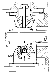
Figure 1 is a partially cut-away schematic representation of a punch for
forming a hole in a seat frame tube in an open configuration;
Figure 2 is a view corresponding to Figure 1 but illustrating the punch in a
closed configuration;
Figure 3 is a partially cut-away schematic view of an extruding die-set in an
open configuration and illustrating a punched seat frame tube prior to
extrusion;

CA 02370811 2002-02-06
-6-
Figure 4 is a view corresponding to Figure 3 but illustrating the die-set in a
closed configuration;
Figure 5 is a partially cut-away schematic view of beading die in an open
configuration illustrating a headrest guide tube inserted through an extruded
opening in a seat frame tube;
Figure 6 is a view corresponding to Figure 5 but showing the die in a closed
configuration and the formation of a first bead;
Figure 7 is a partially cut-away schematic view of a clenching die-set in an
open configuration;
Figure 8 is a view corresponding to Figure 7 of the clenching die-set in a
closed configuration;
Figure 9 is a perspective view of a headrest guide tube secured to a tubular
seat frame member by a combination of clenching and beading;
Figure 10 is a perspective view corresponding to Figure 9 but illustrating
two headrest guide tubes in a longer run of seat frame tubing;
Figure 11 is a perspective view of a pair of headrest guide tubes secured to
a tubular seat frame member.
Figure 12 is a front elevation of two headrest guide tubes secured to a
section of seat frame tubing;
Figure 13 is a perspective view corresponding to Figure 10 but illustrating a
longer run of tubing; and,
Figure 14 is an end elevation of a headrest guide tube inserted through a
tubular seat frame.

CA 02370811 2002-02-06
7
DESCRIPTION OF PREFERRED EMBODIMENTS
Figure 1 illustrates a punch set having an upper member 100, a lower
member 102 and a punch 104 in an open configuration. Figure 1 further
illustrates
a "length" or "run" of ductile metal tubing 50 placed between the upper member
100 and lower member 102.
Figure 2 illustrates the forming of first and second diametrically opposed
axially aligned openings 52 and 54 respectively in the tubing 50. This is
accomplished by bringing the upper member 100 and lower member: 102 toward
the tubing 50 and passing the punch 104 through the tubing 50 and into a
mating
receptacle 106 in the lower member 102. The first opening 52 and second
opening
103 are labeled in Figure 3.
The shape of the tubing 50 in the region of the first and second holes, 52
and 54 respectively, will depend on the configuration of the upper member 100,
the lower member 102 and how closely these members are brought together. The
arrangement illustrated in Figures 1 and 2 provides a flattened region 58
about the
openings 52 and 54. Other arrangements may provide walls about the flattened
area 58 which may provide additional rigidity.
After the "punching" operation the tubing 50 is transferred to an extruding
die-set as schematically illustrated in Figures 3 and 4. The extruding die-set
has a
core 200 and a cavity 202 which is aligned with the core. The punched tubing
50
is placed between the core 200 and the cavity 202 with the first and second
openings, 52 and 54 respectively, aligned therewith. The extruding die-set is
moved from an open configuration as illustrated in Figure 3 to a closed
configuration as illustrated in Figure 4 by passing the core 200 through the
openings 52 and 54 and into the cavity 202. This has the effect of flowing
metal
from about the first opening 52 through the second opening 54 while also
enlarging the first opening 52 and the second opening 54.

CA 02370811 2002-02-06
.. g _
The extrusion process also forms a passage 60 extending through the tubing
with an upstanding wall 62 extending thereabout. The upstanding wall 62 has an
inner wall 64 defined at least in part by metal surrounding the first opening
52 and
an outer wall 66 formed from metal surround the second opening 54. The passage
60 has two ends which for the sake of convenience are herein referred to as an
entrance 68 adjacent the tubing 50 and an exit 70 distal the tubing 50.
The extrusion process forms the passage 60 without removing a significant
amount of metal in contrast with earlier processes. Instead, the passage 60 is
formed by causing metal that would otherwise be removed, to flow into the wall
62 which defines the passage 60. Accordingly, rather than being removed, the
metal surrounding the first opening 52 and second opening 54 is relocated and
therefore available to provide torsional rigidity to the resultant structure.
Figures 5 through 8 illustrate the mounting of a headrest guide tube 80 to
the tubing 50 which may be a tubular seat frame member. As illustrated in
Figure
5, the guide tube 80 may be inserted into the passage 60 as a "blank" tube
(i.e.
having generally straight sides free of projections). The guide tube 80 is
placed
over a mandrel 300 which extends through a second forming member 310. The
mandrel 300 has a shoulder 302 which extends radially outwardly to limit the
distance the guide tube 80 may be slid therealong. The mandrel 300 resists
inward
collapse of the guide tube 80 during forming and thereby maintains alignment
and
a minimum diameter of the inside of the guide tube 80.
The second forming member 310 is configured to closely receive the guide
tube 80 and the wall 62 about the passage 60 through the tubing 50. In a first
position illustrated in Figures 5 and 6, the mandrel 300 is positioned
relative to the
second forming member 310 to abut against the tubing 50 about the wall 62 and
provide support thereabout.

CA 02370811 2002-02-06
-9-
A first forming member 320 is next lowered over the guide tube 80 and
mandrel 300. The first forming member has a receptacle 322 for receiving the
mandrel 300 arid the guide tube 80. The receptacle 322 has a shoulder 324 for
abutting against the end of the guide tube 80 and limiting its travel into the
receptacle 322. Continued movement of the first forming member 320 toward the
tubing 50 as supported by the second forming member 310 will cause deformation
of the guide tube 80 in a radially outward direction in the space between the
first
forming member 320 and the tubing 50. As a result, a bead 82 forms adjacent
the
entrance 68 of the passage 60 through the tubing 50.
It will be appreciated that the bead 82 may be pre-formed on the guide tube
80 before insertion into the passage 60. It is however believed that forming
the
bead 82 while the guide tube 80 is in the passage 60 will cause better
conformity
between the profile of the bead 82 and the passage 60.
The bead 82 acts as a first detent on the guide tube to limit displacement of
the guide tube in a first direction, namely into the entrance 68.
Figures 7 and 8 illustrate the final forming steps. As illustrated in Figure
7,
the first forming member 310 is moved away from the tubing 50 and the mandrel
300 is slid upwardly as illustrated relative to the first forming member 310
to
extend further therefrom. This exposes a portion 84 of the guide tube 80:
The second forming member 310 and the mandrel 300 are next urged
toward the first forming member 320 which is now supporting the bead 82. This
causes some of the exposed portion 84 of the guide tube 80 to deform radially
outwardly into the wall 62 of the passage 60 as shown at reference 86. The
second
forming member 310 restrains the wall 62 from expanding radially outwardly.
This forming operation is referred to as "clenching" and is one manner in
which a
second detent may be formed to, in combination with the first detent (the bead
82)

CA 02370811 2002-02-06
-10-
fixedly secure the guide tube 80 into the tubing 50 which comprises the
tubular
seat frame member.
Alternatively the second forming member 310 may be configured to form a
second bead adjacent the exit 70 of the passage 60. This may be accomplished
by
transferring the guide tube 80 and tubing 50 assembly after the first beading
operation to a further forming member similar to the first member 320 and
forming a bead in much the same way as with the first bead 82.
Figures 9 through 14 illustrate finished assemblies with a headrest guide
tube 80 mounted to a tubular seat frame member of metal tubing 50. A notch 90
is
illustrated in some of the guide tubes 80 which would have to be correctly
oriented
to receive the detent means or to align the insert (not shown) associated with
the
headrest guide posts (not shown) to be inserted therein.
The above description is intended in an illustrative rather than a restrictive
sense. Variations may be apparent to persons skilled in metal forming and such
structures without departing from the spirit and scope of the invention which
is
defined by the claims set out below.

Representative Drawing
A single figure which represents the drawing illustrating the invention.
Administrative Status

For a clearer understanding of the status of the application/patent presented on this page, the site Disclaimer , as well as the definitions for Patent , Administrative Status , Maintenance Fee  and Payment History  should be consulted.

Administrative Status

Title Date
Forecasted Issue Date Unavailable
(22) Filed 2002-02-06
(41) Open to Public Inspection 2003-08-06
Dead Application 2006-02-06

Abandonment History

Abandonment Date Reason Reinstatement Date
2005-02-07 FAILURE TO PAY APPLICATION MAINTENANCE FEE

Payment History

Fee Type Anniversary Year Due Date Amount Paid Paid Date
Application Fee $300.00 2002-02-06
Registration of a document - section 124 $100.00 2002-03-04
Registration of a document - section 124 $100.00 2003-09-25
Maintenance Fee - Application - New Act 2 2004-02-06 $100.00 2004-02-05
Owners on Record

Note: Records showing the ownership history in alphabetical order.

Current Owners on Record
TRITON TUBULAR COMPONENTS CORP.
Past Owners on Record
FRENKE, BILL
JRM TUBE INC.
MCWHINNIE, JOHN
Past Owners that do not appear in the "Owners on Record" listing will appear in other documentation within the application.
Documents

To view selected files, please enter reCAPTCHA code :


To view images, click a link in the Document Description column. To download the documents, select one or more checkboxes in the first column and then click the "Download Selected in PDF format (Zip Archive)" or the "Download Selected as Single PDF" button.

List of published and non-published patent-specific documents on the CPD .

If you have any difficulty accessing content, you can call the Client Service Centre at 1-866-997-1936 or send them an e-mail at CIPO Client Service Centre.


Document
Description 
Date
(yyyy-mm-dd) 
Number of pages   Size of Image (KB) 
Description 2002-02-06 10 482
Claims 2002-02-06 7 238
Representative Drawing 2003-07-10 1 15
Cover Page 2003-07-15 2 46
Abstract 2002-02-06 1 22
Correspondence 2002-03-06 1 24
Assignment 2002-02-06 2 86
Assignment 2002-03-04 3 88
Assignment 2003-09-25 27 865
Fees 2004-02-05 1 33
Drawings 2002-02-06 10 742