Note: Descriptions are shown in the official language in which they were submitted.
CA 02370905 2001-11-13
1
FUEL CELL SYSTEM AND FUEL CELL FOR SUCH A SYSTEM
Scope of the InvEntion
The present invention relates to. a system for supplying a consumer with
electrical
power using a fuel cell device for generating electrical power, and a fuel
tank device for
holding fuel to be supplied to the. fuel cell device.
The invention also relates to fuel cells for such a systam, in particular a
fuel cell device
comprising at least one fuel cell device having a plurality of anode devices,
and a
plurality of cathode devices, where each cathode device is assigned a
corresponding
anode device.
In addition, the invention relates to a stack of such fuel cells (hereinbelow
also called
fuel cell stacks).
Prior Art
Systems with fuel cells of the abovementioned type as well as fuel cells of
the
abovementioned type for such systems are known in the prior art.
These known fuel cell systems are essentially restricted to the high-
performance
application range of several kW. Examples of fuel, cell systems are found in
the
automobile industry or in power plant technology.
In the light-capacity range, that is, of the order of up to 1 to 2 kW, fuel
cells are still
barely being used nowadays as an alternative to batteries or storage
batteries.
CA 02370905 2001-11-13
' ~ 2
This is because known fuel cell systems, which should act as battery and
storage
battery substitute, exhibit poorer properties than batteries and storage
batteries. In
particular, known fuel cell systems cannot guarantee the same running period,
the same
safety, comparable size and comparable weight as batteries or storage
batteries.
In addition, with known systems there are no measures in place to ensure
disposal of
the reaction products.
Whereas with a fuel cell current strengths of clearly over 1AIcm2 can be
achieved, as a
rule electrical voltages of the order of only 0.5 to 0.7V -in the charged
state (1.2V in the
uncharged state) can be achieved with a single fuel cell. Since most small
apparatus
however requires a substantially higher operating voltage, it is necessary to
combine
several fuel cells into one fuel cell device to be able to produce the
required voltage.
It is known to combine several fuel cells into a stacked fuel cell device
(fuel cell stack).
These known fuel cell stacks have, however, a consid~rable overall height and
complex
fuel supply devices, generally preventing their use in small apparatus.
It is also known to arrange several fuel cells on one plane and to connect
them together.
For example, DE 196 36 903 discloses such a planiforrn configuration. The
configuration illustrated in this document comprises a plurality of single
cells which are
each provided gas-tight in a casing. Because when such a fuel cell is
manufactured the
majority of single fuel cells and the corresponding majority of seals must be
placed in
the casing, the manufacture of such a fuel cell device is relatively expensive
and thus
cost-intensive.
In view of these disadvantages of the prior art the object of the present
invention is to
improve the known fuel cell system as well as the fuel cell devices used
therein.
Description of the Invention
The abovementioned task is solved by a system for supplying a consumer with
electrical power of the type mentioned at the outset, which is distinguished
by a disposal
CA 02370905 2001-11-13
3
device for disposing of the waste products originating from operation of the
fuel cell
device.
Through provision of a disposal device fvr the waste products of the processes
running
in a fuel cell the fuel side of the system can be operfated without
interacting with the
environment at all, effectively overcoming a substantial drawback of known
systems.
According to a preferred further. development the c~sposal device can comprise
a
receptacle for holding waste products.
According to another advantageous further development the fuel tank device can
be
designed such that it serves as a receptacle: Due to these measures the
structural size
of the system can be reduced, which in particular enables it to be
incorporated into
small apparatus, such as for example portable computers, power tools,
electrical
domestic appliances, electrical telecommunications eqwipment, portable
television sets,
video recorders and the like.
According to another preferred further development the disposal device can
have a filter
device. This enables the waste products to be separated from one another. This
in turn
facilitates disposal of the elements arising from power generation.
Furthermore, through
such separation a portion of the waste products not impairing the fuel can be
stored in
the fuel tank device. This is incidentally one of the examples for the
abovedescribed
further development of the fuel tank device which also serves as a receptacle.
In accordance with an alternative further development the disposal device can
also
comprise an ion exchange device.
By way of advantage both the filter device and the ion exchange device can be
designed to convert gases generated during operation: of the fuel cell device
into liquid
and/or solid substances. Because of these measures only liquid and solid waste
products remain after power is generated and these are substantially easier to
handle
than gaseous waste products.
CA 02370905 2001-11-13
4
In the system it must be ensured that the fuel cell device always has fuel
available in
sufficient concentration. In addition to this, the fuel must be in contact
with the electrode
arrangement, when positive ions pass through the electrolyte of the anode
arrangement
and when negative ions pass through the electrolyte of the cathode arrangement
of the
fuel cell device.
According to an advantageous further development of the abovedescribed system
a
pump device can be provided to support the fuel supply from the fuel tank
device to the
fuel cell device. The flow, which ensures that unused fuel is always available
to the fuel
cell, can be supported by such a pump device in particular with liquids. In
addition, this
flow also supports removal of waste products.
According to yet another further development the system can also be designed
such
that fuel supply is effected substantially by the pump device. In this
connection the
power supply can be controlled by targeted control of the pump device.
By way of advantage the pump device in the described embodiments can be
designed
in the form of a miniature pump. These measures setae to keep the structural
size of
the system to a minimum.
According to a particularly advantageous further development the pump device
can be
designed adjustably such that the quantity fed to the fuel cell device effects
a constant
output of the fuel cell device. In this connection repeated measurements of
the output of
the fuel cell device serve as output quantities.
An advantage of this further development is that power supply of a consumer is
possible
with constant current and constant voltage, therefore with constant output.
According to another further development the abovedescribed fuel cell devices
can
advantageously be provided as methanol fuel cell devices. Methanol fuel cell
devices
are characterised in particular by the fact that liquid fuel with high-energy
density is
used, resulting in a compact structure of a methanol fuel cell device. In
methanol fuel
cells in particular a methanol-water mixture is supplied as fuel to the anode
device of
CA 02370905 2001-11-13
, ,
the fuel cell. The cathode device is supplied by an oxidant, such as air or
pure oxygen,
for example. Carbon dioxide occurs on the anode and water vapour occurs on the
cathode as waste products of the reactions in the fuel cell.
According to an advantageous further development of the methanol fuel cell
device a
filter device can be used which converts carbon dioxide into a carbonate
present in the
solid phase. In particular, filter devices having calcium carbonate are
suitable here.
As an alternative such conversion can be performed advantageously with an
alkaline
ion exchanger, in particular an alkaline ion exchanger based on synthetic
resin, for
example a hydroxide ion exchanger.
As an alternative to the methanol fuel cell device hydrogen fuel cell devices
can also be
utilised. In this case hydrogen is used as fuel and accordingly supplied to
the anode
device. The cathode device is likewise supplied with an oxidant, oxygen or
air, for
example. Water present in steam form occurs on the. cathode as a reaction
product.
This can be collected in a receptacle. Alternatively, it can also be released
to the
atmosphere. Furthermore, in this embodiment the remaining low-oxygen air must
be
removed from the system. This can occur by being released to the atmosphere.
According to another preferred further development of the abovedescribed
system the
fuel tank device can be designed to accommodate a methanol-water mixture or
hydrogen, and an oxidising agent tank device can be provided to hold an
oxidising
agent, for example pure oxygen or hydrogen peroxide. By way of these measures
the
fuel cell system can be operated as a fully closed-off system, similarly to a
battery or a
storage battery.
Similarly to the pump device on the fuel side a pump. device can also be
provided to
support supply of the oxidising agent from the oxidising:agent tank device to
the fuel cell
device.
According to another further development supply of the oxidising agent can
advantageously be effected essentially by the pump device. As is the case of
the pump
CA 02370905 2001-11-13
6
device for fuel, effective supply of the oxidising agent to the electrode
device of the fuel
cell device can be guaranteed
By way of advantage the pump device can be designed in the form of a miniature
pump.
This again ensures minimal structural size with high functionality.
As for the pump device on the fuel side the pump device on the oxidising agent
side can
also be provided adjustably such .that the quantity of oxidising agent
supplied by the
pump device of the fuel cell device ensures constant output of the fuel cell
device, in
such a way that the output of. the fuel cell device acts as output quantity.
This
embodiment can be implemented alternatively for or together with regulating
the pump
device on the fuel side,
The abovedescribed systems can, according to another further development,
include a
ventilator device for supplying atmospheric oxygen from the atmosphere. An
advantage
of this design is that the ambient air can be used as oxidising agent. A
further
advantage is that the size of the system can be smaller on account of the
oxidising
agent tank device being omitted. Altogether, the system can be manufactured as
a
smaller and more cost-effective unit. Since atmospheric oxygen is utilised,
the efficiency
of the system is, however, reduced when compared to a system operated on pure
oxygen. The excess low-oxygen air can be released into the atmosphere in this
further
development
According to yet another advantageous further development of all the
abovedescribed
systems the overall system, therefore the fuel cell deviEe, the fuel tank
device, possibly
the pump device for fuel and/or for the oxidising agent, the tank device for
taking up the
oxidising agent if required and the disposal device can :be designed as a
module which
can be placed into the consumer for power supply and withdrawn from the
consumer for
refilling. This design enables easy replenishing of fuel and easy replacement
of the
system, whenever it becomes worn.
Alternatively and according to another highly advantageous further development
the fuel
cell device and possibly the pump device for fuel andl~r for the oxidising
agent of the
CA 02370905 2001-11-13
7
system can be arranged on the consumer side. In this case only the fuel tank
device,
the tank device for holding the oxidising agent and the disposal device are
designed as
a module which can be placed into the consumer for power supply and withdrawn
from
the consumer for refilling. In this further development only the actual user
components
of the system can be exchanged.
An advantage of this system is That it can be replenished after the fuel is
used, without
the occurrence of substances which are problematical to dispose of. Even if
the system
has to be disposed of as such, the individual components of the system can be
recycled, without the occurrence_of substances which are problematical to
dispose of,
as is the case with recycling many types of battery or many types of storage
battery.
The underlying task of the invention is also solved by a system of the type
described at
the outset, which is characterised in that the fuel cell device is provided on
the
consumer side and the fuel tank device is designed as a module, which can be
placed
into the consumer for power supply and withdrawn from: the consumer for
refilling.
These measures allow the actual consumer components of the system to be
provided
as exchangeable units. Because single modules can be manufactured relatively
cost-
effectively, these modules can be used to operate a consumer as batteries or a
storage
battery is used, that is, when the fuel is consumed, a fresh module can be
inserted. In
addition to this, since the storage capacity of a fuel cell device relative to
its volume is
considerably greater than that of a battery or a storage battery, the service
life of the
fuel cell device can be increased while the size remains: the same.
This system can be developed further advantageously in a variety of ways. In
particular,
the advantageous embodiments can be used which have already been discussed in
connection with the system, comprising a disposal device. These advantageous
embodiments are itemised hereinbelow; with respect to the advantages
achievable by
these embodiments reference is made to the above discussion of the
advantageous
embodiments to avoid repetition.
CA 02370905 2001-11-13
8
According to another further development the system can be equipped with a
pump
device provided on the consumer side, preferably a miniature pump, to support
the fuel
supply from the fuel tank device to the fuel cell device.
This pump device can also be fitted in such a way that°the fuel is
supplied substantially
by the pump device:
According to a particularly advantageous further development the pump device
can be
fitted adjustably, and certainly such that the quantity of fuel provided by
the pump
device of the fuel cell device effects a constant output flf the fuel cell
device, such that
the measured output of the fuel cell device serves as output quantity.
According to yet another further development a hydrogen fuel cell device can
be utilised
in the system as a fuel cell device.
Furthermore the system can have a pump device on the consumer side, preferably
a
miniature pump, to support supply of the oxidising agent to the fuel cell
device.
According to a further development of the system the supply of the oxidising
agent can
be effected substantially by the pump device.
According to another advantageous further development the pump device can be
adjusted such that the quantity of oxidising agent supplied to the fuel cell
device effects
a constant output of the fuel cell device, such that the output of the cell
device serves as
output quantity. The adjustable pump device for the o~cidising agent can also
be used
here together with the adjustable pump device for fuel.
According to another further development the pump device can also be designed
as a
ventilator device for supplying ambient oxygen from the:atmosphere.
The third aspect of the task underlying the invention; namely improvement of
the fuel
cell device, is solved by a fuel cell device of the type initially described,
which is
characterised in that each fuel cell device exhibits a single, essentially
flat electrolyte
CA 02370905 2001-11-13
9
device, such that each anode device and its corresponding cathode device are
placed
on opposite sides of the electrolyte device.
Hereby it is no longer necessary compared to the prior art to place every
single fuel cell
made up of anode, electrolyte and cathode gas-tight ihto a casing. The
manufacturing
process and thus manufacturing costs of the fuel cell device can thus be
simplified or
reduced substantially.
Alternatively the known fuel cell device is improved by the fact that at least
two fuel cell
devices are provided with a plurality of anode devices, a plurality of cathode
devices,
where each cathode device is assigned a corresponding anode device, and a
plurality
of electrolyte devices, such that an anode device and a corresponding cathode
device
are arranged respectively on opposite sides of a correisponding electrolyte
device and
together form a single cell, where all single cells of a fuel cell device are
arranged in one
plane, and the at least two fuel cell devices are arranged above one another.
In particular, the voltage achievable with the known fuel cell device can
hereby be
increased as such by optimising dimensioning, that is, reduction in size, of
the fuel cell
device.
According to an advantageous further development of these alternatives
corresponding
anode devices and cathode devices can exhibit the same size and form. This
guarantees effective generation of power with minimal structural size.
According to another advantageous further development of the abovedescribed
fuel cell
devices ion-permeable, preferably proton-permeable current conductors, which
are
connected together by a switching device, can be provided between the
electrolyte
devices) and the anode devices and/or between the electrolyte devices) and the
cathode devices.
As an alternative to this fuel-permeable or oxidising agent-permeable current
conductors can also be used which are provided on the anode devices andlor the
CA 02370905 2001-11-13
cathode devices, in such a way that the current conductors are connected
together by a
connection device.
According to a further alternative fuel-permeable or oxidising agent-permeable
current
conductors, which are connected to one another by means of a connection
device, can
be provided in the anode devices andlor in the cathode devices.
The above three alternatives for arranging the current conductors relative to
the anode
devices or the cathode devices can each be inserted singly, that is, for all
electrodes of
the fuel cell device, or they may also be combined in any other way.
In this connection each current conductor can preferably be designed as a
braid or a
thin pertorated plate or a perforated film. Firstly, good contact is ensured
between
current conductor and electrode; secondly, the fuel arid the oxidising agent
can make
contact with the electrode devices without difficulty.
Each current conductor can comprise nickel, platinum, gold, and/or stainless
steel. The
durability of the current conductors can be increased considerably by use of
these
materials.
According to an advantageous further development of the current conductor the
latter
can be approximately the same size as the assigned anode device or the
assigned
cathode device. In this design maximum possible contact between current
conductor
and electrode device is guaranteed and the resistance between current
conductor and
electrode device is thereby minimised.
According to a particularly advantageous further dev~lopment the connection
device
can include strip conductors. This measure can produce particularly simple
connection
of the individual fuel cells. In particular, an integrated circuit can be
realised hereby.
These strip conductors can be attached to the electrolyte device, for example.
j CA 02370905 2001-11-13
In particular, with respect to current conductors which are also attached to
the
electrolyte device (or between electrolyte device and anode or cathode
device), the
advantage of relatively simple manufacture arises. Therefore in one operating
step the
entire current conductor /strip conductor sample can be designed on the
electrolyte
device, for example using processes such as masking, photolithography,
etching,
Layering and the like known from semi-conductor techn~logy.
According to an advantageous further development the connection device can
exhibit a
strip conductor for at least one anode device and a °strip conductor
for at least one
cathode device, such that the strip conductors are connected at the edge of
the
electrolyte device to a connector.
Moreover, the connection device for at least one anode. device and at Least
one cathode
device can have a strip conductor which is guided from the anode side to the
cathode
side on the electrolyte device. The individual cells can accordingly be
connected in
series.
Any arbitrary connection of the individual fuel cells can be realised by
random
combination of both these alternatives. By way of !example, all fuel cells can
be
connected to one another in series by the second alternative and the tap,
therefore the
skrip conductor which is attached at the edge of the electrolyte device to the
connector,
can be provided on the first and fast fuel cell of this series. On the other
hand each fuel
cell can be tapped per se by the first alternative and connected externally in
any
manner. Both these alternatives and a combination of both alternatives open up
a large
number of options for adapting a fuel cell device to the various current and
voltage
requirements of a consumer.
According to an advantageous further development a switch device, which is
designed
to modify the connection device of the anode devices and the cathode devices
of at
least one or at least two fuel cell devices, can be provided. Optimum
adaptation of the
electrical power generated by the fuel cell device to th~ requirements of a
consumer is
enables thereby. Moreover, this adaptation can also be easily altered and thus
adapted
to the requirements of one or various consumers.
, , CA 02370905 2001-11-13
12
By way of advantage the switch device of the fuel cell device can comprise a
connection
device which can be connected to the connection device at the edge of the
electrolyte
device. This connection device may comprise a plug bciard for example.
According to a fu .rther development of the abovementioned fuel cell devices
the
electrolyte device can be provided in the form of a proton-conducting
electrolyte film.
Such a film can be worked and processed relatively easily, keeping
manufacturing costs
of the fuel cell device to a minimum.
The fuel cell device can, according to an advantageous further development,
comprise
methanol fuel cell devices. In this case an electrolyte device including
nafion is
preferably suitable.
The advantages already discussed in connection with the embodiments of the
systems
of a methanol fuel cell device also apply here.
According to an alternative further development the 'fuel cell device can also
have
hydrogen fuel cell devices; in this case electrolyte devices including nafion
are also
suitable.
Here too the advantages of a hydrogen-fuel cell device already discussed in
connection
with the embodiments of the systems apply.
The abovedescribed fuel cell devices can preferably be manufactured by semi-
conductor processes, electroplating processes or other known surface-coating
processes.
According to a particularly advantageous further development of all
abovedescribed fuel
cell devices these can have at least two fuel cell devices, such that each two
adjacent
fuel cell devices are connected to one another by an electrically insulating
connection
device, and each two adjacent fuel cell devices are arranged such that the
anode
devices of the first of these fuel cell devices face the anode devices of the
second of
CA 02370905 2001-11-13
13
these fuel cell devices or the cathode devices of the first of these fuel cell
devices face
the cathode devices of the: second of these fuel celj devices, and each
connection
device has a supply distribution structure for the fuel to be supplied to the
anode
devices or the oxidising agent to be supplied to the catheode devices.
In this way n fuel cell devices can be interconn~cted. For this n - 1 of the
abovedescribed connection devices are required. For the first and last fuel
cell device
elements can be provided which exhibit supply ducts which are open on one side
of the
element only. Alternatively, the abovedescribed connection devices can be
used, where
the supply distribution structure is to be connected to one side of the
connection devices
to prevent the fuel or oxidising agent from escaping.
By means of this further development stacks of fuel cell devices can be formed
and any
voltages corresponding to the respective requirements can be created thereby.
In
particular, fuel cell devices: can be created by these embodiments, whose
output
compared to batteries and storage batteries can be lowered considerably at the
same
voltage. By means of this so-called monopolar connection of the individual
fuel cell
devices minimal structural sizes can be realised, since only one supply
distribution
structure is required for every two cells. Fuel cell devices whose size
corresponds to
conventional batteries and storage batteries can thus be realised.
Alternatively to this and according to another further development the fuel
cell device
can also have a stack shape with at least two fuel cell devices, in which each
two
adjacent fuel cell devices are interconnected by an electrically insulating
connection
device, such that each cathode side of a first of the tvwo fuel cell devices
of the anode
device faces the second of the two fuel cell devices, arid each connection
device has a
first supply distribution structure for the fuel to be supplied to the anode
devices and a
second supply distribution stnrcture for the oxidising agent to be supplied to
the cathode
devices.
This alternative, with which. any voltage can likewise be produced, can be
used in
particular whenever the overall height is less critical. Incidentally, the
advantages, which
CA 02370905 2001-11-13
14
have already been discussed in connection with the monopolar connection of the
fuel
cell devices, also emerge for such a further development with these connection
devices.
According to an advantageous further development of the above latter
alternatives each
connection device can have conducting elements v~hich are arranged such that
it
electrically conductively connects each anode device of a first of the two
adjacent fuel
cell devices with the cathode device of the second of the two adjacent fuel
cell devices
facing it and corresponding to it.
This further development enables different, respectively superposed cells of
different
fuel cell devices to be connected to one another in a stack. In this
connection a bipolar
connection is realised in each stack far superposed fuel cells of different
fuel cell
devices. The different stacks made up in this way need to be connected to one
another
by the uppermost and lowest cell of the stack only. Thereby the connection
expense in
the fuel cell device can be reduced.
The abovedescribed stacked fuel cell devices can, as can the fuel cell devices
having
one fuel cell device only, have a connection device in the form of strip
conductors
according to an advantageous further development.
In this connection the strip conductors can be provided advantageously on or
in the
connection device. The fuel cell device can be :consequently manufactured in
particularly simple fashion. In particular, fuel cell devices and the
connection devices
can be formed by means of processes known from semi-conductor technology.
Accordingly, the fuel cell devices and the connection devices merely need to
be
combined and the fuel cell devices connected.
According to a preferred further development a fuel cell device can be
provided, in
which the connection device ,includes a strip conductor for at least one anode
device
and a strip conductor for at least one cathode device; where the strip
conductors are
connected at the edge of the connection device to a connector.
CA 02370905 2001-11-13
Apart from connection of the individual fuel cells random connecting of the
individual
fuel cell devices is also possible. Here the individual cells can be connected
in different
groups in different fuel cell devices at random, by means of which a plurality
of possible
currents and voltages can be obtained. Such fuel cell devices can therefore be
flexibly
used for a wide variety of applications.
According to an advantageous further development of this embodiment the
abovedescribed fuel cell devices can be provided in a casing, and the
connectors can
extend through a wall of this casing. By means of this particular measure the
entire fuel
cell device can be connected to a corresponding connei~tor and/or switchgear.
Low-temperature fuel cell devices are particularly suitable for use in small
apparatus,
such as portable computers and the like,.
The abovedescribed fuel cell devices are particularly suitable for outputting
less than
approximately one kW.
The discussed systems and the fuel cell devices utilised therein are optimised
for the
low-output range, in particular with respect to their power output and size,
but can also
be used with corresponding dimensioning in other output ranges.
Although not mentioned explicitly, a plurality of the abovedescribed features
can be
combined together, so that the advantages described fbr the individual
features can be
achieved in combination. In particular, all described fuel cell devices are
suited for use
in the systems described at the outset.
Preferred embodiments of the present invention are described hereinbelow with
reference to the accompanying diagram, in which:
Figure 1 shows a first embodiment of the system for supplying an electrical
consumer with power according to the present invention,
CA 02370905 2001-11-13
16
Figure 2 shows a second embodiment of the system for supplying an electrical
consumer with power according to the present invention,
Figure 3 shows a third embodiment des system for supplying an electrical
consumer with power according to the present invention,
Figure 4 shows a fourth embodiment of the system for supplying an electrical
consumer with power according to the present invention,
Figure 5 shows a first embodiment of a fuel cell iievice according to the
present
invention, in particular for use in one of the systems of Figures 1 to 4,
Figure 6 shows a second embodiment of a fuel cell device according to the
present
invention, in particular for use in one of the systems of Figures 1 to 4,
Figure 7 shows a third embodiment of a fuel cell device according to the
present
invention, in particular for use in one of the systems of Figures 1 to 4,
Figure 8 shows a fourth embodiment of a fuel celF device according to the
present
invention, in particular for use in one of the systems of Figures 1 to 4,
Figure 9 shows a fifth embodiment of a fuel cell device according to the
present
invention, in particular for use in one of the systems of Figures 1 to 4,
Figure 10 shows a sixth embodiment of a fuel cell device according to the
present
invention, in particular for use in one of the systems of Figures 1 to 4, and
Figure 11 shows a detailed view of a current conductor in a fuel cell device
according
to the present invention.
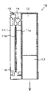
Figure 1 illustrates a first embodiment of a system 10 aiccording to the
present invention
for supplying an electrical consumer with power. The illustration of the
system is, in
CA 02370905 2001-11-13
17
particular with respect to the illustrated ratios of :dimensions, to be
understood
diagrammatically only.
The system comprises a fuel cell device 11 for generating the electrical
power, a fuel
tank device 12 for holding the fuel and a disposal devcce 13 for disposing of
the waste
products resulting from operation of the fuel cell
The fuel cell device 11 comprises an anode area 11 a, an electrolyte device 11
c which is
permeable to ions, in particular protons and impermeable to electrons, and a
cathode
area 11 b. The anode area and -the cathode area can be designed in particular
by a
plurality of anodes or cathodes, as is explained in detail in connection with
the
description of Figures 5 to 9.
Figure 1 illustrates a system 10, in which fuel is supplied to the anode area
11 a, which
is not fully converted, that is, which does not reach the cathode area 11 b
fully after
conversion into ions via the electrolyte device 11 c. Accordingly, waste
substances occur
from operation of the fuel cell in the anode area 11 a, which are disposed of
by the
disposal device 13 which is designed as a filter device in the present
embodiment.
The fuel is supplied from the fuel tank device 12 to the fuel cell device 11
by a pump
device 14.
An oxidising agent is supplied to the cathode area 11:b in the illustrated
embodiment.
When the fuel cell is operating the oxidising agent reacts with the fuel
constituents
which have reached the cathode area via the electrolyte device 11 c. The
illustrated
embodiment is particularly suitable, if innoxious substances occur in the
cathode area,
which can be released to the atmospheric air without risk.
An example for a fuel cell device of the previously described type is a
methanol fuel cell
device. A methanol-water mixture is used here as fuel. Oxygen, for example in
the form
of atmospheric air, is supplied as oxidising agent to the cathode area. A
ventilator 16, or
alternatively a pump device, is used for this purpose.
CA 02370905 2001-11-13
18
Conditional on a catalyst the methanol reacts in the methanol-water mixture in
the
anode area 11 a to protons, carbon dioxide and electrcins. The protons migrate
through
the proton-permeable membrane 11 c, which can be formed from nafion for
example,
into the cathode area 11 b where they react with oxygen ions from the
atmospheric air
and which have been ionised by a catalyst. Water vapour, which is released
along with
the unused portion of the air into the atmosphere occurs here as waste
product.
The electrons resulting from reaction are conveyed from the anode area to the
cathode
area in the form of electrical current.
The carbon dioxide originating in the anode area is flushed along with the
water from
the anode area into the filter device 13. This process, as for the supply of
fuel to the fuel
cell device, is supported by the pump device 14.
In the filter device 13 the carbon dioxide is converted into carbonate. In the
illustrated
embodiment a calcium dioxide filter is used, in which the carbon dioxide is
converted
into calcium carbonate with the formation of water.
An ion exchanger, in particular an alkaline ion exchange device based on
synthetic
resin, can be used as an alternative to the filter device. A synthetic resin
matrix, on
which hydroxide ions are stored, is suitable for this for example. In such an
ion
exchange device the carbon dioxide is converted into calcium carbonate, which
accumulates on the matrix, with the formation of water.
The water resulting from filtering is supplied back to the fuel tank device 12
along with
the unused portion of the methanol-water mixture.
In continuous operation the methanol is caused to react in the methanol-water
mixture,
which is why the concentration of the methanol in' the methanol-water mixture
is
reduced to a value at which the abovedescribed reactaon can no longer be
carried out
efficiently. The Biter device is added by disposal of the carbon dioxide
resulting from
reaction. The available fuel and the filter device are effectively such that
the
concentration value is reached and the filter device is added at the same
time.
CA 02370905 2001-11-13
19
According to the embodiment in Figure 1 the fuel tank device 12 and the filter
device 13
are designed as a module, while the fuel cell device, the pump devices, the
ventilator
device and the supply ducts and outlets not describedin greater detail are
provided on
the consumer side. This module can, as indicated ; by the arrow in Figure 1,
be
withdrawn from the consumer and reprocessed. In addition to this the fuel tank
device is
filled with fuel and the filter device or the ion exchange device is brought
to its original
state by chemical or physical means or completely exchanged.
In the illustrated embodiment-some 5m1 methanol are required for a consumer to
operate for 10 hours with 20 Watt. At a concentration of 4 vol.°~
methanol in the
methanol-water mixture approximately 125m1 fuel mixture are required
accordingly.
Figure.2 illustrates a second embodiment of the system 20 according to the
present
invention for supplying an electrical consumer with power. Depiction of the
system, in
particular with respect to the illustrated ratios of size, is to be understood
schematically
only. In order to avoid repetition hereinbelow reference is made only to the
differences
to the system illustrated in Figure 1 and with respect to the other components
reference
is made to the corresponding description of Figure 1. The reference numerals,
with
which corresponding components are designated, hereby differ by the first
digit
respectively.
An essential difference between the system 20 and the system 10 is that the
system 20
is provided for fuels which are fully combusted. Accordingly, no waste
substances occur
in system 20 on the anode side. The anode area 21 b consequently has no
discharge
and no disposal device.
The fuel cell device illustrated in Figure 2 may be realised in the form of a
hydrogen fuel
cell device. In such a device hydrogen, which is fully converted into protons
by means of
a catalyst, is supplied to the anode. These protons pass through the proton-
permeable
membrane to the cathode area. In the cathode area oxygen is converted from the
atmospheric air into oxygen ions, likewise by means of a catalyst. The oxygen
ions
' CA 02370905 2001-11-13
finally react with the protons to water vapour. The electrons resulting from
these
reactions are taken off as current.
The module removable from the system is formed i~ the embodiment illustrated
in
Figure 2 by the fuel tank device 22.
Figure 3 illustrates a third embodiment of a system 30 according to the
present
invention for supplying an electrical consumer with power. Depiction of the
system, in
particular with respect to the illustrated ratios of size, is to be understood
schematically
only. The system 30 is similar-to the system 10 illustrated in Figure 1.
Therefore, to
avoid repetition hereinbelow reference is made only to the differences to the
system
illustrated in Figure 1 and with respect to the other components reference is
made to the
corresponding description of Figure 1. The reference numerals, with which
corresponding components are designated, hereby differ by the first digit
respectively.
The system according to Figure 3 differs from the systiem according to Figure
1 by the
fact that the oxidising agent is not removed from the atmospheric air and the
waste
products on the cathode side are not released to the atmosphere. This system
accordingly is particularly suitable for fuels whose conversion produces
environmentally-unfriendly waste products.
The oxidising agent is made available in an oxidising aigent tank device 35,
from where
it makes its way into the cathode area 31 a of the fuel cell device 31 by way
of a pump
device 36. The waste products of this process are guided to a disposal device
33 via an
outlet pipe. The disposal device 33 comprises an ian exchange device 33-1 and
a
receptacle 33-2.
The pump device 36 is designed adjustably in this embodiment, and certainly so
that
the quantity of fuel supplied to the fuel cell device effects a constant
output of the fuel
cell device 31. The output released by the fuel cell device 31 is used as
output quantity.
Measurements of the output of the fuel cell device are made continuously by a
meter
(not illustrated) and in the pump rate is increased or decreased dependent on
the
measured output.
CA 02370905 2001-11-13
21
A methanol fuel cell device can again be employed as an example of such a fuel
cell
device.
Pure oxygen is supplied from the oxidising agent tank device 35 to the cathode
area as
oxidising agent by. means of a pump device 36, designed in the form of a micro
pump.
Accordingly, water vapour is the only waste product occurring on the cathode
side. The
resulting water vapour is conveyed to the receptacle 33-2 via a pipe and
stored there.
On the anode side carbon dioxide forms as waste: product in system 30, and is
converted info calcium carbonate in an ion exchange device 33-1, as described
hereinabove, with formation of water. The resulting water is finally fed to
the fuel tank
device 32.
An advantage of system 30 as compared to system 10 is that no waste products
are
released to the atmosphere and that more efficient generation of power can
occur by
the use of pure oxygen.
In the embodiment illustrated in Figure 3 the module which can be removed from
the
system is formed by the fuel tank device 32, the ion exchange device 33-1, the
receptacle 33-2 and the oxidising agent tank device 35.
Figure 4 illustrates a fourth embodiment of a system 40 according to the
present
invention for supplying an electrical consumer with power. Depiction of the
system, in
particular with respect to the illustrated ratios of size, is to be understood
schematically
only. The system 40 is similar to the systems 20 and:30 illustrated in Figure
2 and in
Figure 3. In order to avoid repetition therefore, hereinbelow reference is
made only to
the differences to the systems illustrated in Figures 2 and 3 and with respect
to the
other components reference is made to the corresponding description of Figures
2 and
3. The reference numerals, with which corresponding components are designated,
hereby differ by the first digit respectively.
As with system 20 in Figure 2, system 40 is operated with a fuel which is
fully converted
on the anode side. There are accordingly no waste products on the anode side,
and as
22
a result thereof neither a discharge nor a disposal device:is provided on the
anode side.
And there are no differences apparent between system:30 and system 40.
Hydrogen in particular is suitable for operating system 40, as for the
operation of system
20 in Figure 2. Hydrogen is converted into protons do the anode side without
waste
products. These protons migrate via the electrolyte device and react on the
cathode
side, to which pure oxygen is supplied from the oxidising agent tank device
45, with
catalysed oxygen ions into water vapour. This water vapour can be condensed
into
water by means of a capacitor and then stared in the receptacle 43.
The module which can be removed from the system is farmed in the embodiment
illustrated in Figure 4 by the fuel tank device 42, the receptacle 43 and the
oxidising
agent tank device 45.
The illustrated embodiments of the systems are to be understood by way of
example
only and not as restrictive. By way of example a plurality of fuels, gaseous
or liquid, and
a plurality of oxidising agents, can also be used in the gaseous or liquid
state.
The only stipulation is that the fuel in question can be dissipated by means
of a catalyst
device into ions which can migrate via the electrolyte device, and react on
the cathode
side with ions which result from conversion of an oxidising agent into ions.
In the embodiments illustrated in Figures '1 to 4 proton-permeable
electrolytes were
used. Depending on the fuel being used, however, other electrolyte devices can
also be
used which are permeable for positive or negative ions.
It should be noted that when electrolyte devices which: are permeable for
negative ions
are used the fuel is to be returned to the cathode. With fuel which is fully
converted all
waste products accordingly accumulate on the anode side.
Moreover, all embodiments of the anode devices, the cathode devices, the
electrolyte
devices, the catalysts, and various materials for the fuel cell devices known
to the
expert in the domain of fuel cells can be used in the abovedescribed
embodiments.
CA 02370905 2001-11-13
23
Embodiments of fuel cell devices according to the present invention are
explained
hereinbelow. These fuel cell devices are particularly suited to the
abovedescribed
systems, but can also be utilised for a wide range of applications
Figure 5 illustrates a first embodiment of a fuel cell device according to the
present
invention schematically in section. Depiction of the fuel cell device is to be
understood
schematically only, in particular with respect to the illustrated ratios in
size.
Figure 5 in particular shows a fuel cell device 50 for use in a fuel cell
device according
to the present invention .
The fuel cell device 50 comprises an electrolyte device 55 in the form of an
ion-
conducting membrane, on which three anode devices 51 and three cathode devices
52
are provided.
The anode devices 51 and the cathode devices 52 can be connected to the
membrane
using methods known in the domain of fuel cell tecf~nology. Alternatively, the
anode
devices 51 and the cathode devices 52 can also be applied to the membrane 55
using
processes known from semi-conductor technology, electroplating processes or
other
surface-coating processes.
In this configuration a cathode device 52 is assigned to each anode device 51.
The
anode devices 51 and the cathode devices 52 are the same shape and size. As a
result, the same voltage and the same current are delivered by each
anodelcathode
device. The anode devices 51 and the cathode devices 52 can also be different
in size
and shape, though this leads to the fact that firstly the individual devices
no longer give
out a defined current, and secondly that the current yield is reduced in the
case of
predetermined structural size, as compared to identical~form and size.
Strip conductors 54, which serve to connect the anode devices 51 and the
cathode
devices 52, are also applied to the membrane 55. This can occur by way of
processes
CA 02370905 2001-11-13
CA 02370905 2001-11-13
24
known from semi-conductor technology, electroplating processes or other
surtace-
coating processes, for example.
Figure 5 in particular shows an anode device connection 56a on the edge of the
membrane 55 and a cathode device connection 56b.
In addition, the three individual cells are connectied in series in the
illustrated
embodiment. This is realised by two strip conductors 56c, which are each
guided from
the anode side to the cathode side via the membr~e. Methods known from semi-
conductor technology can also be employed to form sudh strip conductors.
Furthermore, the embodiment illustrated in Figure 5 comprises current
conductors 56d
each of which is provided between the electrolyte device and the anode devices
51 or
the cathode devices 52. The current conductors have openings for ensuring
transport of
ions through the electrolyte device. To increase the service fife of same the
current
conductors 5fd comprise an inert material, such as for example nickel, gold,
platinum,
stainless steel or alloys of the same.
The overall strip conductoNcurrent conductor structure can be designed in the
embodiment illustrated in Figure 5 in a single step, for example employing
procedures
known from semi-conductor technology, such as masking, photolithography,
etching,
coating and the like. Alternatively, electroplating coating processes or other
surface-
coating processes may also be employed.
The fuel cell device illustrated in Figure 5 further comprises a supply device
for the fuel
and the oxidising agent. (not shown). In this connection the fuel is supplied
to the anode
devices; the oxidising agent is fed to the cathode devices.
It must be ensured that fuel and oxidising agent do riot mix in order to
guarantee the
operating safety and functionality of the fuel cell. This is guaranteed in the
illustrated
embodiment by the fact that the membrane 55 used is impermeable for both the
fuel
and the oxidising agent. With respect to the prior art :it is no longer
necessary for the
individual cells to be sealed off from one another. Rather the fuel on the one
hand and
25
the oxidising agent on the other hand can be guided albng the membrane. In
particular,
with use of strip conductors 56c, which are guided from the anode side to the
cathode
side, care should be taken that no leakages occur during operation to hinder
the
functioning of the fuel cell devices.
As explained in detail with reference to Figures 7 to 9, ;several of the
illustrated fuel cell
devices can be combined into one fuel cell device, in this instance designated
as a fuel
cell stack.
Figure 6 illustrates a second embodiment of a fuel cell device according to
the present
invention in a diagrammatic plan view. In particular, Fig~rre 6 shows a fuel
cell device 60
for use in a fuel cell device according to the present intention. The fuel
cell device 60 is
similar to the fuel cell device 50 illustrated in Figure 5. Therefore in order
to avoid
repetition hereinbelow reference is made only to the differences to the fuel
cell device
illustrated in Figure 5 and with respect to the other components reference is
made to the
corresponding description of Figure 5.
The fuel cell device 60 comprises nine anode devices 61 which are arranged on
a
continuous membrane 65. In addition, nine cathode devices are provided which
are
each below the anode devices 61 in the plane of projection. Current conductor
devices
in the form of a perforated structure are provided on the electrolyte device
65 also under
the anode devices 61 and thus are not visible in the plan view.
The essential difference between the embodiments illustrated in Figure 5 and
in Figure
6 is in the switching device. In the fuel cell device 60 ohly strip conductors
66a and 66b,
which are guided to the edge of the membrane 65, are used. The nine strip
conductors
66a are connected to the anode devices 61. The nine strip conductors 66b (of
which
three only are shown in dashed lines, as they are on the underside of the
membrane)
are connected to the cathode devices.
On the edge of the membrane all strip conductors are connected to connectors
in the
form of contact pins 67a and 67b. ,
CA 02370905 2001-11-13
CA 02370905 2001-11-13
26
These contact pins 67a and 67b are arranged such that they can be engaged with
a
plug board of a switch device 69.
The switch device 69 is designed such that the anode devices 61 and the
cathode
devices 62 can be connected in various ways known to the expert in parallel
(for
addition of currents) and in series (for addition of voltages). A plurality of
different
voltages U and currents I can be made available at theoutlet of the switch
device 69.
Apart from the toggling illustrated in Figure 5 and Figure 6 any combination
of the
illustrated embodiments can be implemented, according to application. By way
of
example it is possible to firmly connect an array of the membranelelectron
devices
toggled with one another in series in Figure 6 respectively and to variably
interconnect
the rows by the switch device.
In connection with the embodiments of Figures 5 and 6 it is pointed out that
the use of
strip conductors is to be understood by way of example only and not
restrictively. Any
other connection devices may be employed; for example the anode devices and
the
cathode devices can also be connected by wires.
Figure 7 diagrammatically illustrates a third embodiment of a fuel cell device
according
to the present invention. In this figure also the size ratios ace not shown
realistically for
the sake of clearer representation. In particular, Figure 7 shows a fuel cell
device 70
which comprises three fuel cell devices 70a, 70b and ~Oc, similar to those
described in
Figure 5 and Figure 6.
Each of the fuel cell devices 70a, 70b and 70c has a plurality of anode
devices 71 and a
plurality of cathode devices 72 which are arranged on: a membrane 75. As
indicated in
the fuel cell device 70a, the individual cells of the fuel dell devices 70a,
70b and 70c are
connected together in series by strip conductors, resulting in an increase in
voltage.
The fuel cell devices 70a, 70b and 70c are electrically connected in series
according to
Figure 7.
27
In the fuel cell device 70 the fuel cell devices 70a and 70b, as well as 70b
and 70c are
interconnected by means of connection devices 77a alnd 77b. In this respect
each two
fuel cell devices 70a, 70b and 70c are arranged such that the anode sides of
the
devices 70a and 70b lie opposite the cathode sides of the devices 70b and 70c.
The connection devices 77a and 77b each comprise an insulation material, so
that the
anode devices 71 and the cathode devices 72 of tHio adjacent fuel cell devices
are
electrically insulated from one another.
The connection devices 77a and 77b each comprise a distribution structure 79a
for
supplying fuel B to the anode devices and a distribution structure 79b for
supplying
oxidising agent O to the cathode devices. The distribution structure can be
designed
arbitrarily. By way of example it can be present in the form of a channel
structure or a
porous structure. Furthermore, fuel and oxidising agent can be supplied
parallel to one
another {see Figure 7); it is also possible to supply fuel and oxidising agent
alternatingly. Supply of fuel B and oxidising agent O is indicated in Figure 7
by arrows.
A closing plate 78a and 78b is provided respectively on the outsides of the
fuel cell
devices. As evident from Figure 7 each closing plate has only one distribution
structure.
The distribution structures illustrated in Figure 7 are connected to a fuel
supply and an
oxidising agent feed, as shown for example in connection with the embodiments
described in Figures 1 to 4.
According to Figure 7 the strip conductors are applied to connect the
electrodes to the
membrane 75. Alternatively the strip conductors can also be applied to the
connection
devices 77a and 77b and/or the closing plates 78a anxi 78b. The previously
mentioned
methods can be used for this purpose.
Figure 8 diagrammatically illustrates a fourth embodiment of a fuel cell
device 80
according to the present invention in section. The fuel cell device 80 is
similar to the fuel
cell device 70 illustrated in Figure 7. Therefore in order to avoid repetition
hereinbelow
reference is made only to the differences to the fuel cell device 70
illustrated in Figure 7
CA 02370905 2001-11-13
28
and with respect to the other components reference is made to the
corresponding
description of Figure 7.
The fuel cell devices 80a, 80b and 80c are arranged such that each of the
cathode
sides or the anode sides of two adjacent fuel cell devices lies opposite each
another. As
in the embodiment in Figure 7 the fuel cell devices 80a.'and 80b or 80b and
80c are also
interconnected by connection devices 88a and 88b.
According to the illustrated configuration the fuel cell devices 80a, 80b and
80c are
connected to one another in series (as shown in Figures 8).
As compared to the configuration in Figure 7 it is sufficient in configuration
80 that the
connection devices 88a and 88b each have only one distribution structure for
supplying
the oxidising agent or the fuel.
An added difference between the fuel cell devices 70 and 80 consists of the
fact that in
the device 80 fuel-permeable or oxdant-permeable current conductors 83 in the
form of
a braid or a perforated plate are provided on the anode devices 87 or the
cathode
devices 82. These current conductors are connected to strip conductors which
are
applied to the membrane 85 or to the connection device 88a or 88b.
Alternatively, the
current conductors can also be connected by wires for switching between
electrodes.
Both the strip conductors and the wires can be guided by the connection device
88b.
This is illustrated by way of example in Figure 8 for the. lowest anode
connection 81 a.
Figure 9 diagrammatically illustrates a fifth embodiiment of a fuel cell
device 90
according to the present invention in section. The fuel cell device 90
corresponds to the
fuel cell device 80 illustrated in Figure 8. The sole difference between both
devices is
that the device 90 has a number of electrolyte devices 95 corresponding to the
number
of devices 91 or cathode devices 92. Because in this embodiment there is no
separation
between fuel and oxidising agent due to a continuous membrane, with the
configuration
of single cells it must be ensured that separating the fuel side and oxidising
agent side
of a fuel cell device is otherwise guaranteed. As a result sealing devices 99
are
provided in the embodiment illustrated in Figure 9.
CA 02370905 2001-11-13
' CA 02370905 2001-11-13
29
Incidentally, to avoid repetitions with respect to the remaining components
reference is
made to the corresponding description of Figure 8.
Figure 10 diagrammatically. illustrates a sixth embodiment of a fuel cell
device 100
according to the present invention in section. The fueil cell device 100
corresponds to
the fuel cell device 70 illustrated in Figure 7. It comprises in particular
three fuel cell
devices which each comprise anode devices 101 (101-1:, 101-2), cathode devices
102
(102-1, 102-2), and an electrolyte device 105 (105-1, 105-2).
The most important difference between both devices is that the connection
device 107
has conducting elements 110a and 110b. Each connection device 107 is
accordingly
divided into conducting areas 110a and 110b (horizontal hatching in Figure 10)
and
non-conducting areas (vertical hatching in Figure 10).
The conducting elements 110a and 110b are arranged such here that they
electrically
conductively connect each anode device 101-1 of'a first of two adjacent fuel
cell devices
101-1, 105-1, 102-1 to the cathode device 102-2 facing: it and corresponding
to it of a
second of two adjacent fuel cell devices 101-2, 105-2, '~02-2.
This enables different, respectively superposed cells df different fuel cell
devices to be
connected to one another in a stack. In this connection a bipolar connection
is made in
each stack for superposed fuel cells of different fuel cell devices. The
different stacks
made up in this way need to be connected to one ano$her by the uppermost and
lowest
cell of the stack only. Thereby the connection expense: in the fuel cell
device can be
reduced.
The abovedescribed configuration also results in a distribution structure
modified in
comparison to Figure 7. In particular, the anode devices 101 and the cathode
devices
102 are circulated laterally by the fuel or the oxidising agent in the
embodiment
illustrated in Figure 10.
' CA 02370905 2001-11-13
Incidentally, to avoid repetitions with respect to the remaining components
reference is
made to the corresponding description of Figure 7.
Figure 11 illustrates an' alternative embodiment of a current conductor
according to the
present invention in section. Figure 11 shows a fuel ce)~ which is composed of
an anode
device 111, a cathode device 112 and an electrolyte device. Figure 11 also
depicts a
current conductor which is provided in the anode device 111 or in the cathode
device
112.
The current conductor 116 preferably comprises aperforated film which ensures
passage for ions, as well as the fuel and the oxidising agent. With respect to
the
material to be used the same applies that has already:been carried out with
the current
conductors described in Figure 5 and in Figure 8.
The embodiments described in connection with Figures 1 to 11 are to be
understood by
way of example and not restrictively. '
In particular, the number of fuel cell devices, the number of cells per fuel
cell device, the
permeable membrane or the single membranes, the respectively illustrated
connections
(including use of switch device), the different connection devices (monopolar
plate,
bipolar plate), are independent features and can ba combined with one another
at
random.