Note: Descriptions are shown in the official language in which they were submitted.
CA 02370996 2001-10-18
1
PCT/EP 00/03645
16.05.2001/7521
MOL-11-WO
DEVICE FOR CONTROLLING FLOWING MEDIA
Description
The invention relates to a shut-off flap for pressure
spaces, in particular for vessels or pipelines, with a
flap disc which is pivotable relative to an axis of
rotation in a housing and which, in the sealing
position, closes the throughflow through the housing in
two mutually opposite flow directions in the region of
a seal, the flap disc being arranged eccentrically,
that is to say with an axis of rotation outside a seal
center line, and the axis of rotation passing, in
particular, through a major axis of the shut-off flap.
In pipelines carrying flowing media, the flow is
interrupted by means of valves, slides or flaps. Flaps
are preferred because of the markedly smaller overall
length.
The simplest embodiment of a flap has an axis of
rotation running centrally along the flap disc. An
eccentric form of construction, in which the axis of
rotation runs at a distance from the flap disc, is also
known. This, as a rule, improves the sealing function
of the flap disc, because the seal of the disc is not
interrupted by the rotary shaft led out of the interior
of the housing. Instead, said rotary shaft is seated in
front of or behind the flap disc. Moreover, the axis of
rotation or the rotary shaft is arranged centrally in
front of the flap disc and intersects a major axis of
the shut-off flap and therefore, as a rule, also the
major axis of the pipeline.
CA 02370996 2001-10-18
2
Finally, what are known as double-eccentric flaps are
known. In this type, in addition to the eccentricity
described, the axis of rotation or the rotary shaft is
arranged outside the major axis, that is to say at a
short distance from the latter. This makes it possible
to have a self-closing effect or positive closing for
one flow direction. With regard to the other flow
direction, there is the disadvantage of a permanent
opening pressure, so that a likewise permanent and high
closing force, with a correspondingly high drive
torque, has to be applied. In the long term,
particularly under relatively high line pressures,
leakage points occur which make it impossible to work
safely on the shut-off side of the pipeline.
Against this background, the object of the present
invention is to provide a shut-off flap with an
improved sealing action. Another object is to manage
with lower drive torques.
The object is achieved, according to the invention, by
the characterizing features of patent claim 1.
In a development of the invention it is provided that
the flap disc is self-closing in both flow directions.
That is to say, the last portion of the closing
movement is assisted by the resulting working pressure
acting on the flap disc, irrespective of the flow
direction. In the simplest instance, this is made
possible by a centrally mounted flap disc which, in the
closing position, has surfaces of different sizes
laterally next to the axis of rotation in both flow
directions, both the larger surfaces and the smaller
surfaces in each case being located opposite one
another diagonally with respect to the axis of
rotation. This apparently impossible arrangement is
made possible by a specific thickness of the flap disc
and by a peripheral sealing surface which is sloped in
lateral regions at the greatest distance from the axis
CA 02370996 2001-10-18
3
of rotation. The seal then has laterally a three-
dimensional depth in the direction of the major axis
and in the direction of the diameter. It is precisely
the depth in the direction of the diameter which makes
S it possible to provide different surface conditions for
the two flow directions. That side of the flap disc
which faces one flow is subdivided by the axis of
rotation into a left and a right surface. The
difference between the surfaces is relevant for
generating the closing force. In a view of the flap
disc according to the flow direction and with the flap
disc closing clockwise, a positive closing effect is
obtained when the left surface is larger than the right
surface. The same condition is to be adhered to on the
other side of the flap disc for the other flow
direction. This is possible by means of the laterally
obliquely directed sealing surface, so that what is
referred to as the left flap surface on one side is
larger than the right flap surface (opposite to it) on
the other side.
Preferably, ring-like sealing elements are arranged, in
particular, on the circumference of the flap disc and
are pressed onto the peripheral sealing surface during
the closing of the flap disc. In this case, a
circumferential stress is built up, so that the
pressure is distributed uniformly on the circumference
and there is a high sealing action all-round.
The above-described slope of the sealing surface may be
formed to a differing extent at the edges located
laterally opposite one another or peripherally as a
whole, so that what is referred to as a seat cone or
taper is obtained. The flap disc may also be designed
eccentrically, that is to say with an axis o:f rotation
outside the flap disc or outside an associated seal
center line. In this embodiment, too, in principle,
positive closing in both flow directions is possible.
CA 02370996 2001-10-18
4
Advantageously, the axis of rotation is arranged on the
major axis or intersects the latter. It thereby becomes
simpler to design the shut-off flap. The forces and
torques which occur are virtually symmetrical.
When the seat cone is used or arranged, a large seat-
cone angle is advantageous for reducing the frictional
forces during closing. The seat cone is defined by the
position of the seat-cone axis or taper axis and by the
position of the taper apex. The seat cone must be
selected or calculated in such a way that it is
impossible for the flap disc to be jammed in the
sealing region. A particularly advantageous embodiment
of the invention relates to a shut-off flap with a seat
cone, the latter having a geometric shape determined
according to specific criteria, see, in particular,
Claims 4 - 9.
The position, defined in Claims 7 and 9, of the
peripheral sealing surface may, in other words, be
reproduced as follows:
a. the peripheral sealing surface is part of a taper
envelope, the generatrices of which define the angles
of the sealing surface in relation to the major axis of
the shut-off flap,
b. the generatrices intersect one another in the
region of a taper apex, the position of which can be
defined as follows:
b1. the seal center line intersects the major axis
perpendicularly to the latter,
b2. the axis of rotation of the flap disc is arranged
at a distance (eccentrically) from the seal center
line, in particular on the major axis, and runs
transversely to the seal center line and to the major
axis,
CA 02370996 2001-10-18
b3. with the axis of rotation as the center point, a
sealing circle is defined, the diameter of which is
smaller than the nominal width of the pipeline or of
the available inside diameter within the shut-off flap,
5
b4. intersection points of the sealing circle with
the seal center line are designated as A and C, and the
intersection point of the sealing circle with a~
straight line through A and with the center point is
designated as B, B being located opposite the point A
across the center point,
b5. a flap radius of half the distance from A to C is
obtained,
b6. a line parallel to the major axis is at a
distance from the latter corresponding to three times
the flap radius, both the parallel line and the points
B and C being located opposite the point A across the
major axis,
b7. a tangent to the sealing circle through the point
B intersects the line parallel to the major axis at a
nni n~ c.rhi nh racf; ncc f-ho ~~,-,or ~r,c~
- CA 02370996 2001-10-18
6
virtually as thin as desired in the flow direction. A
flap disc of this type, admittedly, is no longer self-
closing. Instead, a slight holding torque for
maintaining the closed position of the flap disc may be
necessary. However, the drive torque for opening the
flap disc is likewise markedly lower than in the known
shut-off flaps. The drive of the flap disc can have
substantially smaller dimensions than hitherto. This is
a great advantage precisely for quick-closing and
opening flaps.
The use of a floating spring ring as a peripheral seal
on the flap disc is another reason for the easy opening
of the shut-off flap. This spring ring comes to rest,
on the inside, on the conical seat of the peripheral
sealing surface in the flap housing. The more the
spring ring is pressed into the conical seat of the
taper envelope, for example due to a pressure
difference on the two sides of the flap disc or due to
a drive torque, the higher a counterforce (force
compensation) caused by the upsetting of the spring
ring or a countertorque which is responsible for the
easy opening of the flap disc becomes. The angles of
the taper envelope are selected in such a way that
there is freedom from jamming or there is no self-
locking.
Finally, the invention also relates to different
methods for the production of shut-off flaps. These
relate, more specifically, to the machining of the
sealing surfaces on the flap disc and on the housing.
In practice, the seal consists of a peripheral sealing
surface on the flap disc or on the housing and of
corresponding sealing elements on the other part in
each case. For example, a packing consisting of sealing
rings or of lamellar seals may be provided. The sealing
elements are machined in a similar way to the sealing
surface. The flap disc is preferably provided with the
sealing elements.
CA 02370996 2001-10-18
7
Further features of the invention, moreover, may be
gathered from the claims and from the description.
Exemplary embodiments of the invention are described in
more detail below with reference to the drawings in
which:
Fig. 1 shows a section through a centric shut-off
flap,
Fig. 2 shows a section through an eccentric shut-off
flap, with a specific flow direction being
indicated,
Fig. 3 shows the shut-off flap according to Fig. 2
with an opposite flow direction,
Fig. 4
to 6
show a shut-off flap from three different
views, ~to be precise from a top view in one
flow direction, in a vertical section and in
a horizontal section, the latter being
similar to Fig. 1 to 3,
Fig. 7 shows a shut-off flap in horizontal section,
with subsidiary lines for determining a seat
cone or the seal geometry,
Fig. 8 shows an illustration corresponding to that
of Fig. 7 with further subsidiary lines,
Fig. 9 shows an enlargement of a detail from Fig. 8,
Fig. 10 shows a functional assembly, to be precise a
shut-off flap in horizontal section, with a
turntable of a CNC machine,
~
CA 02370996 2001-10-18
8
Fig. 11 shows a housing of the shut-off flap
according to Fig. 10, chucked on the
turntable,
Fig. 12 shows a flap disc according to Fig. 10,
chucked on the turntable,
Fig. 13 shows an illustration similar to that of Fig.
10, but for somewhat different machining,
Fig. 14 shows an illustration similar to that of Fig.
11,
Fig. 15 shows an illustration similar to that of Fig.
12,
Fig. 16
to 19 show geometrical explanations for determining
the dimensions required for the design,
Fig. 20 shows ap illustration of the forces occurring
in the region of a peripheral sealing ring
during the closing of the shut-off flap,
Fig. 21 shows a sealing ring in cross section,
Fig. 22 shows a further graphic illustration of the
forces occurring, according to Fig. 20,
Fig. 23 corresponds to Fig. 21,
Fig. 24 shows an illustration similar to that of Fig.
8 and 16 for explaining a further method of
calculation for the taper apex S1 and the
elliptic shape of the sealing seat,
Fig. 25 shows a projection for a further explanation
of the elliptic shape,
~
CA 02370996 2001-10-18
9
Fig. 26 shows an illustration of the flow cross
section in the shut-off flap to explain the
forces and torques which occur,
Fig. 27 shows an illustration similar to that of Fig.
9 and 17 for a further explanation of the
elliptic shape.
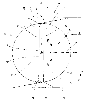
Some important basic concepts of a shut-off flap 10
according to the invention will first be explained with
reference to Fig. 1. A flap disc 11 is arranged in a
housing 12 with a centric axis of rotation 13. Upstream
and downstream pipelines are not shown.
A sealing seat in the housing 12 is designated by the
numeral 14 and has a peripheral sealing surface 15. A
corresponding sealing surface in the region of the flap
disc 11 bears the reference numeral 16. In practice, a
plurality of sealing lamellae may also be provided here
or in the housing.
A major axis 17 of the shut-off flap 10 extends
parallel to the flow directions 18, 19 andY in the
present case, passes through the axis of rotation 13.
More specifically, the major axis 17 occurs as an axis
along the flow directions and through a surface center
of gravity of the flap 11. The major axis is also
normally at the same time the pipe axis.
The sealing surfaces 15, 16 are angled in relation to
the major axis 17, so that dimensions in the direction
of the major axis 17 are obtained (depth TL in the
direction of the major axis and depth TD in the
direction of the diameter). The slope of the sealing
surfaces 15, 16 is greatest where the distance from the
axis of rotation 13 is also greatest. At the passage of
the axis of rotation 13 through the sealing surfaces
15, 16, the latter are oriented parallel to the major
axis 17 and therefore have no slope. By virtue of the
~
CA 02370996 2001-10-18
depth of the sealing surfaces 15, 16 in the direction
of the major axis 17, a seal center line 20 can be
indicated. The intersection point 21 of the latter with
the sealing surface 16 describes a sealing circle 22
5 during the pivoting of the flap disc 17.
In the present case, the flap disc 11 is to be rotated
clockwise in the direction of the arrow 23 for opening
and anti-clockwise in the direction of the arrow 24 for
10 closing.
The shut-off flap 10 is designed in such a way that the
flap disc 11 closes positively in both flow directions
18, 19. In the event of a flow in the direction of the
arrow 18, a right disc side 25 is acted upon and, in
the case of a flow in the opposite direction 19, a left
disc side 26 is acted upon. The two sides 25, 26 may be
subdivided into side surfaces 27, 28 and 29, 30 located
opposite one another, the separation resulting from the
position of the major axis 17. On the assumption of the
flow direction 18, a closing force is obtained due to
the surfaces 29 and 30 being of different sizes. The
side surface 29 is larger than the side surface 30
because of the obliquely directed sealing surface 16.
The conditions are exactly the reverse on the opposite
side 26. Correspondingly, in the case of the reverse
flow direction 19, hereto, a closing force occurs due
to the surfaces 27 and 28 being of different sizes.
The relationships described can also be seen in Figures
2 and 3 with reference to a somewhat differently
configured shut-off flap 31. The directions of rotation
are interchanged here, as compared with Fig. 1. Thus,
the flap disc 32 closes during clockwise rotation,
arrow 33, and opens as a result of anti-clockwise
rotation, arrow 34. The different flow directions are
indicated by the arrows 35 and 36, the housing by
numeral 37, the major axis by numeral 38 and a seal
center line by the numeral 39. Side surfaces of
~
CA 02370996 2001-10-18
11
different sizes bear the designations A1, A2 on the
right side 40 and A3, A4 on the left side 41. As in the
exemplary embodiment of Fig. 1, hereto, closing forces
for both flow directions are obtained.
In contrast to Fig. 1, in Figures 2 and 3 the flap disc
11 has what is known as a cone seat with sealing
surfaces 42, 43 on the housing 37 which are oriented
conically in relation to one another and with
correspondingly arranged sealing lamellae 44 on the
circumference of the flap disc 32. Imaginary
continuations of the sealing surfaces 42, 43 in the
drawing plane meet in a way not shown on the left of
the flap disc 32 and above the major axis 38 and thus
form a taper. A peripheral sealing surface DF as part
of a taper envelope is obtained in the circumferential
direction. An obliquely directed line 45 passing
through the seal center line 39 and the major axis 38
constitutes the taper axis.
In contrast to the shut-off flap 10, the shut-off flap
31 is designed to be slightly (double-) eccentric, with
a center of rotation 46 just next to the major axis 38.
The selected eccentricity, to be precise the distance
of the center of rotation 46 from the major axis 38, is
small, but nevertheless such that closing forces occur
in both flow directions on account of the surface
distributions. In the present case, the distance is
smaller than half the depth TD of the sealing surface
of the sealing lamellae 44. In this case, TD is
obtained in the direction of the seal center line 39
transversely to the major axis 38, see also Fig. 1.
Figures 4 to 6 show three views of a shut-off flap
illustration which is close to reality. This is, again,
an eccentric flap with the same construction as in
Figures 2 and 3. The same reference numerals are
therefore provided. A rotary shaft 47, pipe flanges 48,
49 and bearings 50, 51 for the rotary shaft 47 can be
~
CA 02370996 2001-10-18
12
seen in addition. It is clearly evident from Fig. 5
that, with the rotary shaft 47 vertical, the sealing
surfaces have only a slight inclination in relation to
the major axis 38 in an upper circumferential region 52
and a lower circumferential region 53. There is, of
course, a smooth transition between these
circumferential regions and the lateral circumferential
regions with the sealing surfaces 42, 43. In actual
fact, the regions 52, 53 are also at an angle to one
another correspondingly to the "cone seat" described
with reference to Figures 2 and 3.
The design of the "cone seat" and therefore the
angularity of the sealing surfaces 42, 43 or of the
circumferential regions 52, 53 are explained in more
detail below with reference to Figures 7 to 9. The
design of a shut-off flap according to Figures 4 to 6
is assumed here. The same reference numerals are used
accordingly.
A pipeline to be ,closed has a nominal diameter DN. The
flap disc 32 is, of course, somewhat smaller in
diameter. In the present case, contrary to Figures 4 to
6, the latter is arranged centrally (only single
eccentricity due to the arrangement of the axis of
rotation outside the seal center line), with the center
of rotation 46 through the major axis 38. The latter is
also at the same time the pipe axis here. The sealing
circle 55 is obtained about the center of rotation 56
in conjunction with an intersection point A of the seal
center line 39 and of the sealing surfaces 42, 43 to be
. constructed. At this stage, the diameter in the region
of the sealing surfaces 42, 43 is known or may be
assumed as a precondition. Only the conical orientation
of the sealing surfaces has to be constructed.
A straight line through the center of rotation 46 and
the intersection point A leads automatically to an
opposite intersection point B. An intersection point C
' CA 02370996 2001-10-18
13
is obtained, opposite the intersection point A, along
the seal center line 39 and on the sealing circle 55.
By means of the points A, B and C, subsidiary lines are
constructed, to be precise a tangent T1 to the sealing
circle 55 through the point A and a straight line G1
through the points B and C. The straight lines T1 and
G1 intersect one another at the point S0.
By the segment A - B being displaced along the tangent
T1, the point A comes to lie on the point S0, whilst
the point B defines a new point S1. Starting from this
point S1, taper lines K1 and K2 are drawn through the
points A and C. The taper lines K1, K2 describe the
circumference of a taper (generatrices), which at the
same time defines the cone seat in the shut-of.f flap 31
or the angles of the sealing surfaces 42, 43 and of the
associated sealing elements on the flap disc 32.
As a result, the point S1 is at a distance a from the
major axis 17, 38 which corresponds to three times the
radius rK of the flap disc 32.
A taper axis KA runs from the intersection point S1
through the flap disc 32, specifically between the
center of rotation 46 and an intersection point 56 of
the major axis 38 and seal center line 39. The above
described position of the taper axis KA is a secondary
condition for the closing action in both flow
directions.
In the figures, in each case, the housing 37 has the
peripheral sealing surface and the flap disc 32 has
sealing lamellae 44. In actual fact, these elements may
also be interchanged, so that, for example, the flap
disc 32 has smooth sealing surfaces.
The production and machining of the sealing surfaces or
lamellar assemblies are explained below with reference
' CA 02370996 2001-10-18
14
to Figures 10 to 15. In this case, the flap discs 32
are each arranged single-eccentrically, with the center
of rotation 46 on the major axis 38.
Figures 10 to 12 illustrate the production of the seat
cone. Thus, Fig. 10 illustrates a functional overview,
with the flap disc 32 and the housing 37 being
illustrated. In actual fact, the two parts are
manufactured independently of one another, according to
Figures 11 and 12.
According to Fig. 11, the housing 37 is chucked in a
specific angular position in an auxiliary fixture 60.
The angle a is obtained between the major axis 38 and
the taper axis KA. The latter is at the same time the
axis of rotation DA for a turntable 61 explained below.
The auxiliary fixture 60 is arranged fixedly on the
turntable 61. A rotating tool 62, for example a milling
cutter or a grinding wheel, is held above the auxiliary
fixture 60. The tool 62 is oriented with a cylindrical
surface 63 parallel to the taper envelope or to the
taper line K1. This results correspondingly in a
straight machining line 64 due to the removal of
material by the tool 62, in the present case in the
region of the peripheral sealing surface on the housing
37. The tool 62 rotates about an axis 65 which runs
parallel to the desired contour of the sealing surface
and to the taper envelope.
Machining takes place in what is known as a CNC milling
. center. The turntable 61 in this case constitutes the
B-axis. During machining, the peripheral sealing
surface 42, 43 is worked out of the housing 37 as a
result of the relatively rapid rotation of the tool 63.
At the same time, and, as compared with this, slow
rotation of the turntable 61 takes place, in
conjunction with an axial movement of the tool 62
according to the arrow 66. The exact orientation of the
~
CA 02370996 2001-10-18
tool 62 according to the calculated taper envelope and
the likewise exact positioning of the housing 37 by
means of the auxiliary fixture 60 are important:.
5 According to Fig. 12, the flap disc 32 is provided with
sealing lamellae 44. Their outside diameters must
likewise be adapted to the seat cone or the taper
envelope. For this purpose, the flap disc 32 is
fastened on the turntable 61 on a further auxiliary
10 fixture 67 and is machined by means of the tool 62 in
the same way as the housing 37 was previously, but from
outside. The axis 65 accordingly lies outside the taper
envelope (taper lines K1, K2). During machining, as a
result of the rotation of the table 61, an observer
15 sees the movement of the housing 37 and of the flap
disc 32 as a wobbling movement. The peripheral sealing
surface lies, in spatial terms, on the envelope of the
calculated taper. The geometric conditions result in an
elliptic shape for the sealing surface.
A somewhat different type of machining is shown in
Figures 13 to 15. Fig. 13 shows, again, an assembly of
all the parts, in a similar way to Fig. 10.
Fig. 14 shows the machining of the housing 37. In
contrast to Fig. 11, here, a non-rotating tool 68 is
provided, which has a cutting edge 69. The housing 37
is again fixed in an auxiliary fixture 60. The latter
is chucked in chucking jaws 70 of a lathe chuck. For
machining, the housing 37 is rotated about the taper
axis KA (at the same time the axis of rotation DA),
whilst the tool 68 is moved merely in the direction of
the arrow and parallel to the taper envelope, see the
arrow 71.
The production of the contour in the region of the flap
disc 32 again takes place by machining from outside, in
a similar way to Fig. 12.
CA 02370996 2001-10-18
16
Instead of the production methods described, others may
also be used, for example machining by lasers or water-
jet cutting.
The calculation of the construction data is explained
below with reference to Figures 16 to 19. The indices
and variables used differ from those given above. For
construction purposes, the pivoting radius of a shut-
off flap is given as R and the distance a from the axis
of rotation to the sealing plane is given as (WAU).
R derives from the requirement for the nominal width. a
results from static reasons of rigidity (material
selection, pressure requirements, etc.). The axis of
rotation passes through the pipe axis.
The following applies: R = segment MU, of course
also
segment MV and MW
a = segment MA .
Determination of the dimensions necessary for
construction:
Determination of the angle a:
cos cr =R ~a=arcco R Equa t i on ( I . )
Determination of angle /3:
a a
sin/3=R~~(i=arcsi R Equation ( II . )
Determination of angle Y:
y=90°-~3=90° arcsi~a
R Equation (III.)
CA 02370996 2001-10-18
17
Determination of segment ~:
UW= 2UA=2atan a=2ata arcco a
R
Equation (IV.)
Determination of the point ~ through segment W~
WSZ=UWtan 'y=2ata arcco a a 90° arcsi a
R R
WS~,=2ata arcco a to 90°-arcsi a
R R
Equation
(V.)
For further calculation, the position of point ~ must
be determined:
The subsidiary right-angled triangle consisting of the
boundary points ~'~andr is congruent with the triangle
bounded by the points U, V and W.
The following
therefore applies: Segment ~r=2a
Segment r~~=2UA (see Equation
IV . ) .
The following therefore applies to segment T~
T~=WSZ--~r=WS2-2a
T~=2ata arcco a to 90°-arcsi a 2a
R R Equation (VI.)
The size and position of the taper angles can then be
determined as follows:
TW _ hS2 _ UW _ 2UA
tan cp = T~ T~ T~ T~
" CA 02370996 2001-10-18
18
a
2ata arcco -
R
2ata arcco a to 90°-arcsi a -2a
= arc tan R R
Equation (VII.)
Determination of the angle
TU TDJ+UW 2xTW 2xUW
t an ~- --
T~ T~h T~ T~h
a
4ata arcco -
R
~=arctan
2ata arcco a Jta 90°-arcsi a 2a
R R
Equation (VIII.)
The taper angle '~ therefore becomes:
a
4ata arcco -
t9 ='~- cp =arctan R
2ata arcco a to 90°-arcsi a 2a
R R
a
2ata arcco -
R
-arctan
2ata arcco a to 90°-arcsi ~ 2a
R R
Equation (IX.)
The position of the taper center is described by the
angle:
_~ ~ _~ ~ _ ~l+ ~P
2 2 2 Equation (X.)
CA 02370996 2001-10-18
19
Using for the ratio of the axis of rotation distance a
and the
a
radius R: R
a simplified notation is obtained for the above
equations from (I.) to (X.).
a
2ata arcco
If, moreover, the term R is replaced by
the concept 6,
the equations I to X can be shortened as follows:
oc=arccose
Equation (I.)
Equation ( II . ) ~-=~rcsin~
Equation (III. ) Y=90°-arcsinE
Equation (IV.)
Equation (V. ) W~=6tan~90°-arcsinEJ
Equation (VI . ) T~=~'tan~90°-arcsinE}--2a
a
=arctan -
Equation (VII . ) ~ 6tan~90°-arcsinE~ - 2a
26
~=arctan
Equation (VIII . ) 6tan90°-arcsinE 2a
Equation (IX.)
fl=arctan 26 -arctan -
6tan90° -arcsin~ 2a 6tan90° -arcsinE -2a
Equation X.
CA 02370996 2001-10-18
6
arctan 2~ +arctan
Qtan~90° -arcsin~~ -2a atan~90° -arcsin~~ -2a
2
The forces during the closure of the shut-off flap are
5 explained below with reference to Fig. 20 to 23. The
flap disc is provided with a sealing element in the
form of sealing lamellae 44, see Fig. 2 and 3. For
simplification, Fig. 20 to 23 assume a single spring
ring 71. This may alone form the sealing element of the
10 flap disc or, together with further thin sealing rings,
produce a lamellar assembly. It is assumed below that
the sealing element of the flap disc is relatively
thin, and therefore only the single spring ring 71
floating in a peripheral socket or groove is provided.
During the closing of the shut-off flap, the spring
ring 71 comes to bear on the peripheral sealing seat of
the flap housing. By virtue of the rotating closing
movement, arrow 72, a high pressure acts on lateral
region 73, 74, which is caused by the tapered shape of
the sealing seat, comparable, for example, to the run
onto an inclined plane.
No inwardly directed forces act on the upper
circumferential region 52 and the lower circumferential
region 53, since, here, the spring ring 71 intersects
the axis of rotation (center of rotation 46).
Accordingly, in these circumferential regions 52, 53,
an outwardly directed pressure of the spring ring 71
30, occurs as a reaction. The spring ring 71 therefore fits
automatically into the sealing seat. The forces which
occur are uniformly distributed or transmitted by
virtue of the elasticity of the spring ring 71. It is
important for this purpose, at the same time, that the
spring ring 71 be mounted in such a way that the latter
can execute adapting or yielding movements transversely
to the flow direction.
CA 02370996 2001-10-18
21
Fig. 22 illustrates graphically the forces which occur.
A contracted circle 75 defines the various forces by
means of its deviation with respect to the outside
diameter of the spring ring 71. In the lateral regions
73, 74, the pressure forces acting on the spring ring
71 from outside are the greatest, whilst, in the upper
and lower circumferential regions 52, 53, the reaction
forces resulting from them predominate. These are, of
course, directed outwards.
The elliptic shape of the flat disc or of the sealing
seat is explained below with reference to Fig. 24 and
25. As already illustrated above, the sealing seat,
that is to say the peripheral sealing surface in the
flap housing 37, is part of a taper envelope with the
taper apex S1. Since the taper apex S1 does not lie on
the major axis 38, the associated taper section runs at
an angle to the taper axis KA which is different from
90° and is in the form of an ellipse. The peripheral
sealing surface thus has two diameters corresponding to
the dimensions of an ellipse which are customary in
mathematics, to be precise a large diameter 2a and a
small diameter 2b. In this case, in Fig. 24, the large
diameter 2a corresponds to the segment between the
points A and C. The small diameter 2b, the height of
the flap disc 32, results from a line 76, perpendicular
to the taper axis KA, through a point p, this
perpendicular intersecting the intersection point 56 of
the seal center line 39 with the major axis 38.
Intersection points s and t of the line 76 with the
envelope lines K1 and K2 of the generated taper can
also be seen. The small diameter 2b is equal to the
distance between the points s and t along the line 76.
According to Fig. 24, the point S1 lies on a line 77
parallel to the major axis 38, the parallel line 77
being at a distance from the major axis 38
corresponding to three times the flap radius rk (rk=
' CA 02370996 2001-10-18
22
the distance between the points 56 and C). The location
of the point S1 on the parallel line 77 is obtained
from the tangent 78 to the sealing circle 55 at the
point B (or the point V in Fig. 16 to 18). Thus, the
further the center of rotation 46 is away from the seal
center line 39 (eccentricity of the shut-off flap), the
further the point Sl travels on the parallel line 77 to
the left in the direction of the seal center line 39.
The elliptic shape of the peripheral seal can be
understood from Fig. 25. A taper with a taper apex Z
and generatrices Z1, Z2 has a taper axis ZA which at
the same time is the bisecting line of the taper angle
A section through the circular taper through a point
H at half the height of the taper and perpendicularly
to the taper axis ZA results in intersection points H1,
H2 with the generatrices Z1 and Z2. The associated
oblique taper section is marked by a double line. This
consists of two portions D1 and D2 of equal. length,
both in each case having the length a. The point H
between the portions D1 and D2 does not lie on the
taper axis, but at a distance from the intersection
point p of the taper axis. The distance between the
points H and p is a measure of the eccentricity
according to the rules for calculating an ellipse. To
be precise, the linear eccentricity a of an ellipse is
obtained as a = az-b2 and the numerical eccentricity
is obtained as ~ = e/a.
Depending on the position of the oblique taper section,
the point H comes to lie at a greater o:r lesser
distance from the taper axis ZA. In this respect, some
taper sections, starting from the point ZS are depicted
in Fig. 25. The height of the ellipse of the taper
section through the point H can also be seen. The
ellipse has a height 2b which corresponds to the
distance between the points H1 and H2. The points H and
p of Fig. 25 correspond to the points 56 and p in Fig.
CA 02370996 2001-10-18
23
24. For greater clarity, the portions D1 and D2 are
also depicted there.
The particular feature of the shut-off flap according
to the invention, precisely in conjunction with a
relatively thin spring ring or sealing ring, is the low
actuating torque, as compared with conventional shut-
off flaps. In the case of a theoretically infinitely
thin sealing ring, the forces described in the
introduction, causing a self-closing or self-holding
effect, no longer occur. Due to the symmetrical flap
arrangement - axis of rotation on the major axis 38 -
single eccentricity - the forces prevailing on both
sides of the flap disc as a result of different
pressures are compensated. The actuating torques
necessary for opening and closing the flap are
relatively low. A drive can have correspondingly small
dimensions.
With the flap closed, different pressures on the two
sides of the flap,disc give rise to a slight flexion of
the latter which, of course, is greatest at mid-height
- along the X-axis in Fig. 26. Due to the flexion and
the previously explained taper-seat arrangement, a
transverse displacement of the sealing ring or spring
ring 71 occurs. However, this transverse displacement
is so slight that it only slightly increases the
actuating torques required. The torques taking effect
perpendicularly to the closed flap disc after the
displacement of the spring ring 71 are explained below
with reference to Fig. 26 and to the resulting
equations. The explanations also apply to thick sealing
rings or assemblies of sealing lamellae and to the
resulting different torques on both sides of the flap
disc. The following apply:
A,=2 f ydx with y=f~x~ (XI . )
' CA 02370996 2001-10-18
24
a
Az=2 f ydx with y=f ~x~ (XII . )
f yzdx
Sx,='d
ZJ Yax
f
(XIII.)
a
y2~
Sxz-'~t (XIV. )
2 f yax
EMi=0=M, -~M z +~M ~ ( XV . )
DM=M,-Mz (XVI. )
d a
d ~ Y2C~JC a ~ Y2C~x
OM = P*2* J ydx* ' ~ - P*2~ ydx* " a
2 j ydx . d 2* f ydx
f (~
(XVI
I.)
d a
f Yzdx a f Yzdx
oM =~' f yax* ~ f yap'' a
f j ydx ~~ f yax
(XVIII.)
1 1
MR(~>=FA*R ~ 2sin ~p (XIX. )
wi th ~0'~~ 80' ~ and R=a+b and 0,9_< b <_ 1
2 a
The spring ring 71 with the associated flap disc forms
a surface in the form of an ellipse with a long
' CA 02370996 2001-10-18
diameter 2a (width) and a short diameter 2b (height).
The center of rotation 46 of the flap disc is arranged
so as to be offset with respect to the bisecting line
(y-axis) of the width of 2a. In conjunction with a
5 pressure difference on the two sides of the flap disc,
a resultant torque occurs, which assists or brakes an
adjustment of the flap disc, depending on the direction
or the sign. The areas on both sides of the
perpendicular line defined by the center of rotation 46
10 are calculated by means of the equations (XI.) and
(XII. ) . The function applicable to an ellipse is to be
adopted here as the function y - f(x). By means of the
general formula y = f(x), the torques on flap discs of
a different shape can also be calculated by means of
15 the equations (XI.) to (XVIII.). The function merely
has to be determinable. The effective lever arms are
determined by means of the position of the pressure
centers of gravity SX1 and SX2, see equations (XIII.)
and (XIV.). The resultant torque, see equations (XV.)
20 to (XVIII.), is obtained from the difference between
the individual torques, these being determined via the
effective pressure p, the calculated areas A1 and A2
and the effective lever arms SX1 and SX2. In equation
(XVIII.), the respective quantities are substituted and
25 as far as possible are cancelled out. The end points c,
d and a which are important for the integral can be
seen from Fig. 26. c and a are at the same time the
lateral edge points of the spring ring 71 after the
transverse displacement of the latter or the lateral
edge points effective on that side of the flap disc
which is viewed in each case, whilst d marks the
. location of the axis defined by the center of rotation
46.
Equation (XIX.) describes, in general, the bending
moments occurring on the circumference of the spring
ring 71 in Fig. 20, as a function of the angle cp of the
radius R with respect to the horizontal, and triggered
by the pressing of the lateral regions onto the cone
' CA 02370996 2001-10-18
26
seat of the peripheral sealing surface DF during the
closing of the flap disc. FA designates the force
taking effect in this case. The values for (1/~t - 1/~ sin
cp) in the right-hand column of the following table are
to correspond to the arrows, shown in Fig. 22, between
the contracted circle 75 and the circumference of the
spring ring 71. Equation (XIX.) reproduces a very
accurate value for the moment MR(cp), insofar as b/a is
between 0.9 and 1.
Table to Fig. 20 and 22
cp , lf~ sin __ { 1 /7t-~ since)
0 180 0 0.318
10 170 0.087 0.231
160 0.171 0.147
150 0.250 0.068
140 0.321 - 0.003
130 0.383 - 0.065
120 0.433 0.115
11,0 0.470 0.152
100 0.492 0.174
90 0.5 0.182
Finally, Fig. 27 also shows the installation of the
15 spring ring 71 in the flap disc 32. The spring ring 71
is held in a peripheral groove 79 which is formed by
the flap disc 32 and a holding ring 80 which is screwed
to the flap disc and the diameter of which is somewhat
smaller than the outside diameter of the spring ring
20 71. A sealing ring 82 is arranged opposite the holding
ring 80, that is to say on the other side of the spring
ring 71, in an axially directed groove 81 of the flap
disc 32, so that a medium shut off by the flap disc 32
cannot flow past the spring ring 71 on the inside.
Fig. 27 contains another special feature. The ellipse E
depicted represents a taper section on the side of the
spring ring 71 on the right in the figure, along the
' CA 02370996 2001-10-18
27
line LR. In this case, the ellipse E is bisected by the
major axis 38 which intersects the center of rotation
46 and the point 56. If, instead, the taper section
were to be taken along the left-hand side of the spring
ring 71, there would be an intersection point of the
corresponding taper section line (not shown) with the
line bisecting the associated ellipse, exactly at the
point PL, depicted as a small cross in Fig. 27.
The cone seat of the peripheral sealing surface DF is
sharply defined by the taper apex S1 being :indicated
and produces a main taper which is designated in this
way here. A cone seat with another basic taper is not
ruled out. It should be possible to have tapers, the
taper apex of which lies more closely to the major axis
38 and at the same time also more closely to the seal
center line 39 than S1, see Fig. 24. This applies
particularly to taper apices which lie within the main
taper, that it to say between the generatrices K1 and
K2.
In the exemplary embodiments described above, the taper
provided is always a circular taper. In actual fact, a
taper of a different shape is also possible, for
example one in which the taper section for generating
the peripheral sealing surface has a circularly round
shape. In general, a taper section perpendicular to the
taper axis should have a purely convex circumferential
line or no concave portions. Only single eccentricity
of the flap disc is important, at most only a slight
distance of the axis of rotation from the major axis
(slight double eccentricity), so that only slight
differences in torque occur for different flow
directions.
*****
' CA 02370996 2001-10-18
28
List of reference symbols
Shut-off flap 49 Pipe flange
11 Flap disc 50 Bearing
5 12 Housing 51 Bearing
13 Axis of rotation 52 Circumferential
reg ion
14 Sealing seat 53 Circumferential
reg ion
10 15 Sealing surface 55 Sealing circle
16 Sealing surface 56 Intersection point
17 Major axis 60 Auxiliary fixture
18 Flow direction 61 Turntable
19 Flow direction 62 Tool
20 Seal center line 63 Surface
21 Intersection point 64 Machining line
22 Sealing circle 65 Axis
23 Arrow 66 Arrow
24 Arrow 67 Auxiliary fixture
25 Right disc side 68 Tool
26 Left disc side 69 Cutting edge
27 Side surface 70 Chucking jaw
28 Side surface 71 Spring ring
29 Side surface 72 Arrow
30 Side surface 73 Lateral region
31 Shut-off flap 74 Lateral region
32 Flap disc 75 Circle
33 Arrow 76 Line
34 Arrow 77 Parallel line
35 Arrows 78 Tangent
36 Arrows 79 Groove
37 Housing 80 Holding ring
38 Major axis 81 Groove
39 Seal center line 82 Sealing ring
40 Right side
41 Left side a Distance
42 Sealing surface A Intersection point
43 Sealing surface B Intersection point
44 Sealing lamellae C Intersection point
CA 02370996 2001-10-18
29
45 Taper axis A1 Side surface
46 Center of rotation A2 Side surface
47 Rotary shaft A3 Side surface
48 Pipe flange A4 Side surface
DN Nominal diameter
E Ellipse
G1 Straight line
KA Taper axis
K1 Generatrix
K2 Generatrix
LR Line
PL Point
rK Radius of the flap disc
SO Intersection point
S1 Construction point
T1 Tangent
a Angle