Language selection

Search

Patent 2371136 Summary

Third-party information liability

Some of the information on this Web page has been provided by external sources. The Government of Canada is not responsible for the accuracy, reliability or currency of the information supplied by external sources. Users wishing to rely upon this information should consult directly with the source of the information. Content provided by external sources is not subject to official languages, privacy and accessibility requirements.

Claims and Abstract availability

Any discrepancies in the text and image of the Claims and Abstract are due to differing posting times. Text of the Claims and Abstract are posted:

  • At the time the application is open to public inspection;
  • At the time of issue of the patent (grant).
(12) Patent Application: (11) CA 2371136
(54) English Title: TUBE-FORMED ROCK BOLT
(54) French Title: BOULON D'ANCRAGE TUBULAIRE
Status: Deemed Abandoned and Beyond the Period of Reinstatement - Pending Response to Notice of Disregarded Communication
Bibliographic Data
(51) International Patent Classification (IPC):
  • E21D 21/00 (2006.01)
(72) Inventors :
  • ARVIDSSON, THOMAS (Sweden)
(73) Owners :
  • ATLAS COPCO ROCK DRILLS AB
(71) Applicants :
  • ATLAS COPCO ROCK DRILLS AB (Sweden)
(74) Agent: SMART & BIGGAR LP
(74) Associate agent:
(45) Issued:
(86) PCT Filing Date: 2000-02-07
(87) Open to Public Inspection: 2000-12-14
Availability of licence: N/A
Dedicated to the Public: N/A
(25) Language of filing: English

Patent Cooperation Treaty (PCT): Yes
(86) PCT Filing Number: PCT/SE2000/000229
(87) International Publication Number: SE2000000229
(85) National Entry: 2001-11-16

(30) Application Priority Data:
Application No. Country/Territory Date
9902065-3 (Sweden) 1999-06-04

Abstracts

English Abstract


Tube-formed rock bolt with closed profile intended to be anchored in a bore
hole. The bolt is anchored in the bore hole through internal pressurisation
with a fluid, for instance water, so that its diameter is plastically expanded
into contact with the wall of the hole. The bolt has before its expansion a
cross-section whose peripheral length exceeds the circumference of the hole
but a largest diameter, which is smaller than that of the hole. In order to
obtain a profile being sufficiently flexible for expansion and at the same
time having a sufficiently large cross-sectional area for the strength the
tube has a varying wall thickness in a peripheral direction. This is achieved
by making the tube-formed bolt by means of extrusion of an aluminium-based
material.


French Abstract

L'invention concerne un boulon d'ancrage tubulaire doté d'un profil fermé destiné à être ancré dans un trou de forage. Le boulon est ancré dans le trou de forage par pressurisation interne par un fluide, par exemple, de l'eau de telle façon que son diamètre soit plastiquement élargi et qu'il vienne en contact avec la paroi du trou. Avant son expansion, le boulon a une section transversale dont la longueur périphérique excède la circonférence du trou mais son diamètre le plus large est inférieur à celui du trou. Ain d'obtenir un profil qui soit suffisamment flexible pour l'expansion tout en ayant une zone section transversale suffisamment large aux fins résistance, le tube a une paroi dont l'épaisseur varie dans la direction périphérique. A cet effet, le boulon tubulaire est réalisé par extrusion d'un matériau à base d'aluminium.

Claims

Note: Claims are shown in the official language in which they were submitted.

Claims:
1. Tube-formed rock bolt comprising an elongated tube (1), which in a cross
section has a peripheral length which exceeds the peripheral length of a
circle having a
diameter being equal to the largest transverse dimension of said tube, two end
closures
(2,3) on said tube and a passage (4) at one of said end closures (2,3) for
pressurisation of a
room (5) surrounded by said tube (1) for expansion of said tube against a bore
hole,
characterized thereby that said tube (1) has a varying material thickness in a
peripheral direction.
2. Tube-formed rock bolt according to claim 1, characterized thereby
that said tube (1) is manufactured by means of extrusion.
3. Tube-formed rock bolt according to claim 1 or 2, characterized
thereby that said tube (1) comprises an aluminium-based material.
4. Tube-formed rock bolt according to any one of claims 1-3,
characterized thereby that said tube (1) is symmetrical about two longitudinal
sections (6,7) which are perpendicular relative to each other.
5. Tube-formed rock bolt according to any one of claims 1-3,
characterized therby that said tube (1) comprises a number of substantially
triangularly formed stiff parts (8) and intermediate U-shaped deformation
parts (9).

Description

Note: Descriptions are shown in the official language in which they were submitted.


CA 02371136 2001-11-16
WO 00/75489 PCT/SE00/00229
Tube-formed rock bolt
The present invention relates to a tube-formed rock bolt with closed profile,
which is
inserted in a bore hole and then expanded into contact with the wall of the
bore hole
through plastic deformation by means of internal pressurisation.
In a previously known rock bolt, see e.g. US-A-4 509 889, a comparatively thin-
walled
tube of mild steel is used, which during manufacture is deformed such that its
peripheral
length is larger than the circumference of the bore hole. A drawback with this
formation is
that the tube is relatively thin-walled in order to allow deformation against
the wall of the
bore hole. This gives a comparatively small cross-sectional area, which
restricts the tensile
strength of the rock bolt. The unsymmetrical form of the rock bolt gives as
result that the
contact force against the rock varies along the periphery, which limits the
load carrying
capacity. A further drawback is that the steel material is exerted to
corrosion attack.
The present invention, which is defined in the subsequent claims, aims at
achieving a tube-
formed rock bolt having a substantially higher tensile strength. This is
achieved primarily
because the rock bolt comprises a tube, which has a material thickness varying
along the
periphery. Through this one can increase the cross-sectional area of the tube
substantially at
the same time as one has parts, which are easily deformed so that the rock
bolt gets a
secure grip against the wall of the bore hole. The advantageous embodiments of
the
invention given in the subclaims give as results that the rock bolt obtains
good corrosion
resistance, is easy to manufacture and gives a good contact force against the
wall of the
bore hole around the hole.
Two embodiments of the invention are described below with reference to the
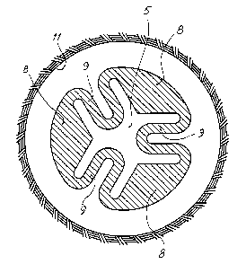
accompanying drawings in which fig 1 shows a tube-formed rock bolt in
perspective with
one end closure removed in order to show the cross-sectional form. Fig 2 shows
a cross
section through the bolt according to fig 1 and schematically the surrounding
bore hole in
which the rock bolt is to be anchored. Fig 3 shows an alternative embodiment
of the
invention.

CA 02371136 2001-11-16
WO 00/75489 PCT/SE00/00229
2
The tube-formed rock bolt shown in the drawings comprises an elongated tube 1
provided
with two end closures 2,3. In the shown example the end closures are made as
caps, which
sealingly have been connected with the tube 1. Through this a room 5 is
created between
the tube 1 and the end closures 2,3. This room can be pressurised via a
passage 4 at the end
closure 2. The end closures can be achieved in other ways. The essential is
that the ends of
the tube 1 are sealed so that one through pressurisation of the room 5 can
expand the tube 1
to contact against the bore hole 11. The tube 1 is, for instance, made by
means of extrusion
of an aluminium-based material, e.g. EN-AW 6082-T4. The tube 1 can thereby
advantageously be given cross-sectional forms like those shown in figs 2 and
3. By making
the profile symmetrical relative to the longitudinal sections 6,7 one obtains
a relatively
even distribution of the contact force between the tube 1 and the bore hole 11
after
expansion of the bolt. One obtains about the same result with the bolt form
shown in fig 3.
This means that the bolt can be loaded more heavily without gliding in the
bore hole. The
bolt shown in fig 2 comprises four substantially triangularly formed parts 8,
which have
large cross-sectional areas and thus large stiffness and tensile strength.
These parts are
connected by means of U-shaped deformation parts 9. In order to increase the
flexibility the
tube profile has been provided with a number of circularly formed parts 12 at
the
deformation parts 9.
When a rock bolt is to be anchored in a bore hole the bolt is pushed into the
bore hole with
the end closure 3 at the inner end of the bore hole. Then pressure fluid is
supplied via the
passage 4 to the room 5 surrounded by the tube 1. Through this the tube 1 is
expanded so
that it contacts the wall of the bore hole 11 hardly. Then the room 5 is
unloaded whereby
the tube 1 remains firmly anchored, since the previous expansion has deformed
the tube 1
plastically.
The invention can, of course, be varied within the scope of claim 1. The
profile can, for
instance, have more or fewer than four stiff parts. An example of this is
shown in fig 3.

Representative Drawing
A single figure which represents the drawing illustrating the invention.
Administrative Status

2024-08-01:As part of the Next Generation Patents (NGP) transition, the Canadian Patents Database (CPD) now contains a more detailed Event History, which replicates the Event Log of our new back-office solution.

Please note that "Inactive:" events refers to events no longer in use in our new back-office solution.

For a clearer understanding of the status of the application/patent presented on this page, the site Disclaimer , as well as the definitions for Patent , Event History , Maintenance Fee  and Payment History  should be consulted.

Event History

Description Date
Application Not Reinstated by Deadline 2006-02-07
Inactive: Dead - RFE never made 2006-02-07
Deemed Abandoned - Failure to Respond to Maintenance Fee Notice 2006-02-07
Inactive: Abandon-RFE+Late fee unpaid-Correspondence sent 2005-02-07
Letter Sent 2002-06-04
Inactive: Correspondence - Transfer 2002-05-30
Inactive: Cover page published 2002-05-07
Inactive: Courtesy letter - Evidence 2002-05-07
Inactive: Notice - National entry - No RFE 2002-05-02
Application Received - PCT 2002-03-07
Inactive: Single transfer 2001-12-13
Application Published (Open to Public Inspection) 2000-12-14

Abandonment History

Abandonment Date Reason Reinstatement Date
2006-02-07

Maintenance Fee

The last payment was received on 2005-01-06

Note : If the full payment has not been received on or before the date indicated, a further fee may be required which may be one of the following

  • the reinstatement fee;
  • the late payment fee; or
  • additional fee to reverse deemed expiry.

Patent fees are adjusted on the 1st of January every year. The amounts above are the current amounts if received by December 31 of the current year.
Please refer to the CIPO Patent Fees web page to see all current fee amounts.

Fee History

Fee Type Anniversary Year Due Date Paid Date
Basic national fee - standard 2001-11-16
Registration of a document 2001-12-13
MF (application, 2nd anniv.) - standard 02 2002-02-07 2002-01-31
MF (application, 3rd anniv.) - standard 03 2003-02-07 2003-01-06
MF (application, 4th anniv.) - standard 04 2004-02-09 2004-01-08
MF (application, 5th anniv.) - standard 05 2005-02-07 2005-01-06
Owners on Record

Note: Records showing the ownership history in alphabetical order.

Current Owners on Record
ATLAS COPCO ROCK DRILLS AB
Past Owners on Record
THOMAS ARVIDSSON
Past Owners that do not appear in the "Owners on Record" listing will appear in other documentation within the application.
Documents

To view selected files, please enter reCAPTCHA code :


To view images, click a link in the Document Description column (Temporarily unavailable). To download the documents, select one or more checkboxes in the first column and then click the "Download Selected in PDF format (Zip Archive)" or the "Download Selected as Single PDF" button.

List of published and non-published patent-specific documents on the CPD .

If you have any difficulty accessing content, you can call the Client Service Centre at 1-866-997-1936 or send them an e-mail at CIPO Client Service Centre.

({010=All Documents, 020=As Filed, 030=As Open to Public Inspection, 040=At Issuance, 050=Examination, 060=Incoming Correspondence, 070=Miscellaneous, 080=Outgoing Correspondence, 090=Payment})


Document
Description 
Date
(yyyy-mm-dd) 
Number of pages   Size of Image (KB) 
Representative drawing 2002-05-05 1 16
Abstract 2001-11-15 1 69
Claims 2001-11-15 1 28
Drawings 2001-11-15 2 74
Description 2001-11-15 2 97
Notice of National Entry 2002-05-01 1 194
Courtesy - Certificate of registration (related document(s)) 2002-06-03 1 114
Reminder - Request for Examination 2004-10-11 1 121
Courtesy - Abandonment Letter (Request for Examination) 2005-04-17 1 166
Courtesy - Abandonment Letter (Maintenance Fee) 2006-04-03 1 177
PCT 2001-11-15 7 264