Note: Descriptions are shown in the official language in which they were submitted.
CA 023713412002-O1-29
<~~.~L.~~r~:'x'lF~.r....~-~,~~,1~C.~~~~~.'St'~ C~>'~'l~r~~3c'~
;~'ield cad the Tnventicaza
The pres~rzt :in~t;:cztiarz relates ~e~~xaiiy to can~~yox s~fstr.-~zs azz~~,
rx~ur~,
~ ~a~rCi~ularly, try ~ ~rzz ity auxiliaz;r c~n~~ey~r ao:r trru~~~z-
tin.c~~tzzi:ners, ~.rtictilaxl~=
ind.ustri~ ttaies ara~i bu~~s, to a ~~or~statioz'.
,~ 'Tia~ic~:( Cans:icier~tiorts
.~,rz c~n~:cain~ n~~d i~ industrial ~t~ti~tic~ns ~v~c~rti:ii~~ a i:i.
~.it~t.~I
prcadctctio:n spaoe pxortttction line is to pxa~uid~ axz ~:i'~c~i~rzt ~ri~l
~t~:~p~rt;si~~ r~~y raf
~ t~ d~livrz-i:~~ arts to the prc~r3ucti~r~ ~:rc~c~.ss. ~'ro~~x~;tion lines,
zzs i"car ~~x~~trz.~aL~ i:rr the
~~ttamoiaz.ie industry, r~c~ttire a l~r~~ nurrzb~r ~~' inrTi~ir~u~l ~~zrts tea
be delivered ~o n
~,:~r~stat~c~n ~ the, li:tae far i~c~ria~rati~rt into tize ~arc~clu~a ka~in~
rz~<~rtctFactzzr~cl.
~l~tracaa~t~~I ov~rlund~;r li.n~~ fcee~ syst~nts k~av~ b~~rz ~l~~~elo~a~ti to
zz~.~.~ciz~aizt: assm~ly
line parts h~ndiin~~ici~zacy. These ~utcaat~c~ c~v~r!vz~ci~r .line feed
systezxzs laroGfi~
1 ~ arz utzi~fierrtrpt~d cavv o:~ ptzrts carried in c;~~t~iz~~;rs car r~,ol~ .
Tlxe in~ivi~~~I ~~:~carl~wrs
t the ryor~sta icon take parts xorrc:~h.e dc~uery ccant~iaa~r car .rao~ c1
i:zzatatl rzero an
the work produot iza r~a~ss, ~s for e~~rn~:lex ~ cue-, ~rz ~~~npie ~:F ~t
e~an~eraticaxt:-iI
~a~e ~'eeci systezx~ is ciisclcised in ~,T.S. :Patent ~Io. 4,x'7"7,~z3~.
~n an~ny prcadue iorz l~z~.~s, it is not iln~t~z~at for tie ~~ar~ proz:tct to
?P urtd~r~o several ~i~si~rz cta~,~es ox m~rci:i:Ez~~tic~ns c~uriz~~ tire
prca~iuct's c~an~r~e:c~ia~I
IiEetirrze: I:n which c;~tses, it is necessary 'to pro~rict~ tie
~arocittcfii~zz li:rze worker ~:rit~
dit~'erezlt or :ne~u eorz~,~c~.nertts or ~ dif:f~r~nt r~uzrah~r off'
copzaz~ents For which the
ori~inzll aver~~tnd~~r line ~e~ system may nit f~~ve been ciesi~z~~~ or r~i
~ec~sioneci tca ,
accazxizxzcadate. Often, these ne~° components tat~e the tczimx o:i'
sixzall ,~~rts ~~l~:ic~l, if
~~ not able to be del:iv~re~ ~i~. the ari~i~al o~~erluza~er Izne ~eecl system,
are typie~Ily
delis ~xec~ tca the ~rcariC~;r izz separ~tt; p~l:lets o:r boxes th~i ire ~e~
at Vitae ~~orkstatican,
Thus, durzn~ the prod2xetion ;process, ~~Ze v~~nr~.er rrzust rant only s~iect
p its delz ereei
Ct~:roz:t~h the ori~i~n.~ 1i a :feed system but must zzls~ select
<~r~c~i~tian~l parts ~xoz~a tlz~
pallets delivered to t~~e workstation. This pa~etic;e terzc~5 to cit~tter ~f~e
cvo~lcstxztion.
~0 .~.riditionally~, xec~tzi.rin~ the ~~oricer to hick .park o~Ft of tkze
wallets o~ the float is tirizz
end zaot er~canozically desirable. ~t.~alacz:n~ t#~ze o~rez-~'ttnc~~r lizae
feer~ system with a
new sysiedesi~zc;d to accoxtzrxzodate the rzew parts :is not ty~ical:l;r ~rz
option c~Lt~; tca
the .E~i~h cast o.f such systems. t~z~td, e~,Yert if ~ :rzew systczn ~~,~ns
a.ttsiai.lec~i, tfzere is nd
CA 023713412002-O1-29
r ,
~~~.~~~e~ th~.t ti;ae ~war~ product ~vili tat undergo ~ddiCac~r~ai
r.~r~difi~~.tia~s car ~b~~ages
requizin~ fi~thex de~i~ eb.~nges to the line ~eec~ syste~rn.
Therefore, it ~a~ld b~ adv~nt~~~r~~s to halide 4~ ~c~ra~ey~~- systeua. ~:~t1
etbod oFdeliveng partta tt~ a practuctian li~z~ wa~~st~~on ~i~hich xeduae a~
einate
at mast saEne a:l'the dr~wb~~~CS clisc~~~~d aba~de.
~~S~~R.~:~''T'ION CAF T:F~I:E C~:~~~:i't~a
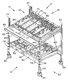
Fig, 1 is ~ perspective vx~v~ a~~n asseEaled ~~~~i~i~ry conv~yar a~~th~
a.nvez~tioxt, ,
Fig. ? i.s a pars~e~ci~re, partza~~y explnc~eci. view of a ~a~ivey~r fr~crze
o:~
a:e i~Z~entian;
Figs; 3~-~~ show sage of 'the vndi~id ~.l comptrnents Gnat to scale] that
cart be ea~bined. to dorm the; at~~ili~ry ccinveyo:r of :~i~. ~;
~x~, :~ is a partial pexspecti~e ~ie~v off' axa; e:~erhpi~~y ~:or~n~~L:i..~~
arrangement bet~,r~en the ca~rnponents of the Canveyrc~r frame of F:ig. 2; ~zd
I ~ ' Fig. 5 is ~ ~,~e~~~; at' the cannec~~;~ rac~,~erx~e~t pat' ~'i~. ~ ass
seen tn
creation t~ in Fig. 4.
~~~R~' ~3F TF~ ~V E~iTI~N
,~ ca~v~yar ofi the invenizon is ~a~a.ed y a .t'"r~~me h~~ang a first szde
~d second side. ~.t least ane evincible and retcac~able su~pn~t extends
berir~=eez~
.~~ the ~xst ~d secand sides s~~~i~ tta~t ~r dist,~rt~e between the ~.~t ~:ad
secoe~d sides is
selecti~reiy adj~st~Ie. At ~e~st one can~eyar t~~c:~ is rcmarabiy ~a~ountecl
o~ the
Vie.
.A.noxhex acc~i.liacy canveyar of the i.~ ent.ioz~ anclu.es ~ :Er~me h~.~i.n~
pair aF spaced apart front legs azid a pair a~ spaced apart bank legs, writh
each beg
2S h~.~ring at least ane attachment elerr~en't. .fit lest one extensihle azacl
~et~a~;tabte ~rar~t
suiaport extends betr~een the ~~ont Legs end ~t 1e st ozie e~tensi.hle end
ret~aet~bl~ bacl~
suppart exiencls between the back 1e ss. Eaclx snplaa~rt . vincludes ~t least
tine
enaagc~zent xrzember conf'~gured to releasahly engage attrv~hsn~nt eleoaent an
a.ne ...
o~ the legs such that the positions, e.g., hei~l~t, of the front and back
e:~tensible aid
30 retractable suppa~s on t lae leis is ad] testable. i~.t ae~st pan ~
ca~veyor tt~ael~ i
remc~vah:ly :rno~~nted an the conveyor :~rs~.e end at le~si cane side r~1
extends bet~.een
each pair of fro~i and back legs: Each side rail includes st least o~te
eng~~~.men~t
rzae:cnber conli~c~red to releasably engage az~ attachment elenxent can a:ne
oFtl~e Ie~.
.:~_
CA 02371341 2002-O1-29
~ ~~xrth~r carlv~yc~r i:rzclud~s .~ irr~ab b~~viri~ a pair ~a~s~ac~d ~~a~rt
~~cnt
leis wd ~ pair o:~' spdc~~i ,,part back Legs; ~~ritb oath 1~; ~~ iris ~
plurvlity of
s;tt~.chm~rzt ~l~.~nts. .r~ plura3at~ off" ext~~sibt~ sad ~e~aet~bl~ ~~o~at
su~pr~.~ts ~a~te~
b~t~~r~~n d ~r~ rcci~~~dbiy e~~~~~s:b:(e ~;vitb ~t~~ ~'rc~nt Ief;s. ~~~:h
:~'ra~a s~~~
iz~clut~~s at l.cone e-~~:a~err~e~.t ~ae~aber at ~ac~ ~ac~ cra.~~r~c~, to
r~~e~s~bi~r ~~a~
~ttsch.a.t ~;l~zzt ara arse of the front l~~s. ~. plurality off' ~xt~asxblc
and
retractablc back sup,~arCs e;ctenci b~t~sr~~n ~n~ ~:r~ z-~:~~as~,bl~~
~o.~a:c~t~:(~; ~~i:clx the b
~~~s. E~c~ ba~~ suplaort inch.~c~es ~t Z~asfi one ~r~aer~cta.~ tncrrs~s~r ~t
e~cb ~~ad
' co~:~~~uxed to rel~~sabiy en~~~~ ~x3 att~ke,~t ~l~mt c~~t ane of the back
i~~s. ,.fit
1~ ic~st rr~c side rr~ix exte~cis b~t4vcc~ ~aci is :r~l~;~sa3~iy e:n~;~.~c~bic
urith each .pair b:E~
frar~t a~a.~ rear legs. At losst o~a~ track' br~c'~et is r~le~s~bly ~,~~;~~eti
~~rith e~.ch frost
ar~ct b~c~c subpart. .Aa ie~s~t ohe cc~n~e~rc~r trach~ ~~te~~~s bet~reeeach
~aair of fro~t.and
beck seaports grad is configured to ea~~.~e the track brackets:
~~a~~~~~~~~~~~~~~ ~ , . ,
~ls ~t he~r~in, spatial. or c3ir~ctic~:~a~J: t~r~.~s, such as "left", "ri,~t",
°z~c~~t", :back", ~l ~c l~k~, ret~te tc the :i~~en ic~xa ~s xt is
~h~r~~c~z~ in the c~rawi~
fires. I~or~eve~; it is to 'bc un~.ers~c~c~i thst tic inv~c~tiart :m~~
ass~.~me v~at~c~s
atte~ativc ori~utatinns c~ corci:i:~~l~, succh i~r~s ire got tc~ b~
con~;ictcre~
zr~iti~~. further, ~s used hereixa, ill czu:~be:rs exlar~ssir~~ dime:nsicns,
physical
~t5 characteristics, aa~d sc f~rt~, us~i ixz the speci~ics~on ans. cl~ixcis
ire tc b~ t~~derstoc~d
as beiza~ mc~di~eci in X11 instances by the tei~ "~bc~ux". ~.ccorc:~~(y,
unless :ineiicated
tb the ec~ntrary~, the nuxnerics:l values set ;Fc~.rth ixv the fa~lar~in~
speci~catio~ ~r~~1
clai~aa tnay nary cl~pendin~ upt~:~ the dcsi~ed ~rorties sou~t 'to be
trbtai:ncti by the
present inventions. .At the: very least, ~d nat as an. ~tte~capt tc limit dxe
alxxplication of
2S the doctrine o~ equivalents t4 the s~v.~e ol' tie c.ivirrzs; c~ch
raur~wri~vl parameter
~hc~uld at last be cflnstrued i.~ la~lat of the number c~.f xelaarted
si~tai~cant digits and by
~pply~~ orc~~z~uy rounding tcch~:iques. l~Ior~er, ~,ll ranges d,zsclosF:d
herein arc to
be und~rrstci~ t~ enc~rrzp~ss any and aI1 subr~rges subsunaeci ih~rci:rt. ~~r
e:~~.mlale, ~.
stated range ~f "1 to lf3" should be considered to ~incl~tcfe any gad
~Ilsubran~~s
~0 betwe~ (and. .inclitsave a~ the z~rt~znt~am vs.ly~; of 1 end the
m~°~in~urz~ value o:F '10;
that is, alI subraxzaes bcginnin,~ ~~i~h a crtir~imu:~a ~=~.iue o~ l tar
rncire ~~~d ez~cting ~rith
~~cim~axn ~falue of :1t7 or less, e.g., 5.5 tc~ 1~.
' 'The stxuctr~~zI cc~:mpanents of an ex~;z~xplary ce~rt~ey~x i~zcorporting
...
fey ores a~ the in~eation w-iil ~~x 1~e ciescr'zb~d and theta the ~~se of dae
cori~reyc~r tra
-~-
CA 02371341 2002-O1-29
p:ra~tice an exemplary method a~ the it~ventiad G~il~ b~ described. It :is to
b~
~uac~~x~itrc~d tha tie specifically dzs~lasec~ caav~ey~iy~~~~d ~ethacl are
p:resez~tec~ i:~r~plv
to explaixz the general caz~c~pts a:f tlae in~ent~ra~ and ti~at the
~r~v~;at:ion as neat ~i~ii~ed. to
these ~p~cihc embodiments.
S ~,s shore particu~~.rly ire Figs. .1 d 2~ tea. exemplary a~~iyiar~
conveyer I(~ of the ~:ravecatior~ izael c~~s wu~ e~pax~c~aki~~, adj~.~stable,
end t~~;c;aza:finrcible
~-arne l?. For pc~rposes a:f the :~'al~owi:n,~ di.sc~tss~a~~, tlxe exemplan,~
ea:r~:~eyar ~~ ~n~i
~e ~.2 s~ao~.~ iri Figs. .~ d: ~ ~i~~ ~e d~sc'~ed a~ h~,~in~: a ant 'f ~., a
~6ac~ t~,
Ief~ side ~ ~, a;nd a .r~~ sade '?~7. Hn~~ever, it is to ire t~nclerstr~ad
that t~ze dareotional
terrx~s ~tre 'far exp~~:nat~ar~ p~z~pa~es n~v ao~. such terrxzs ~:re xaot~ td
he earzs~dexed ~
lamatazag to the inver~taa~a,
~s sha~r~ ~n ~'z~s. 1-a~, the fr~.me 12 h~.s ~ plz~ality c~f su~paa-t~ ar
legs ~~ preferably made of z-igad rn.~iexial, such as plastic or metal, e.~.,
alurz~~ra~.un,
steel, etc. Tn the e~enzplazy ~:rnbbdim~:x~t shoc~r~ in F gs. l a~ad :2, the
legs ~2 are
I S svbstxn iax:ly T.,-saZaped an crass se~;t~nn having ~ cwt pan t ~=~
e~tendi:~~ at a
sbstaaati~l~y rz.ht abgle a a seca~.d part 2~. ~?, ,p:l~~rrility of s~aeed
sttaehezat
ea~~ts 3~ are cried an ar l't>xxxaaed on the legs ~2e.g,, can at least dr~~
al' the parts
~~ or 26, e.g_, the first pert 2~. For exaxnpae, as ~~ara~ ra. ire Fags. 2, ~,
and ~, the
dtta.chn~ent el~merats ~~3 can b~; can~gu~-ed as eye-scats bv~ng ~. larger
diameter area
32 ad;~acertt a smaller diameter area ~~. forever, ~~~~ s~.utable
cc~n~r~cztioz~~l
attaclaxnent systexra, e.g,, balt ladles, hanks, b~.yc~net rnaa~zts, etc.,
cc~~:~lil be used. °"C~ae
legs 22 ca~a. be made of a say piece ox, x1' desired, tlae legs 2.2 can be
e;~teras~ble and
retr~.ctable, e.b., farrried by ~vo ar rrnare telescap~z~g ar cxxutuaaay
sladable pikes that
carp be selectively lacked ~n aa~r ca:r~ e~fiion~.l rtza~er tea adjv~st the
aeng~h ca' the leis
~°i 22, Thin lodkinb can be done in~ any canvent:ir~nl ~ar~e:r, saach
as but pat .liza~ited to
pix.~ ax bolts passing fhrough. al'zgZaed holes is °t~e leg pieoes,
~rietic~n clamps, etc.
Looking at the (rant l ~# of the fr~e 1 ~, at least c~~e c1 preferably
mare than one (rant suppoxt a.r :Iaa~i beam 3d e~c~ends betu~reer~ and :is
re~e~sah.ly
carrnectzd to or e:ngageable with the Ieft curl right fZ~o:rtt aegs 22. Fax
e~.arrz~plt., a I~w~.r
3(J load beam 3b ca.n ~ poslta.oned year the bottar~~s of ~.he front leis 2~
arzd ~ upper
laid beam 36 can be lt~cated above the la~ve~x laid barn 36. As shown ~ Figs.
l, ~,
and 3B, each bead 3~ is preferably extensible .abaci x~tradtsblo; e.g., is
tel~scopac,
sdjustab:(e, ar rrtav~ble between a :first, retr~cterl ,posi~tlar~ atxcl octe
or mare secc~rzci,
elongated ax e~pattded pasitzans. ~rf o~t~ ~xempl~y ernbc~dimertt, the bearzx
3~a can tie
CA 02371341 2002-O1-29
firmed ~y a substantially ~-sb~gaci a~tt~r rn~mber 38 end a s~bs~an~i~tl~ L~-
s~~p~ct
~ne~' member ~L3 slid.able ~lo:~~zv ox in the outEx rrt~:c~zber a~. T:1~oc~tw
~~~mbr ~~
~zacl~.~des ~ b~~ ~2 haling riva sides ~~ exte~~cl~~ svbst~i~lly
~a~nt~~~.l~~~r frorrz
the basc ~2. T~~o bas ~? anc~lor c~tz~ ox ~nr~re o~ t~~~; s:id~s ~.=~ can
inclvicle c~r~~ or ~or~
~ bores ~.b, e.g.. th~e~cled bo~-~s, to er~~a~e a locking device ss ~xpl~inecl
in ~.nr~r~ d.~~~.il
b~laru. The inner zn~rczb~r ~tt} also bas ~. bssc ~~ ~uit~a t~vr~ szd~s
5~~ctnc~irl~,.~
s~bstac~ti~i~y ~~andic~~arly th~e~rar~z. The b~.s~ ~.8 ~.dJor c~n~ or mare o:f
the sides
S4 naay b~.v~ oar ~xz~ar~ hares c~:r, zra one ~mb:c~eliaent, To~~~~d,
:laz~~~tudirzal slots
52. The slots 52 are oonfi~uretf to ~li~n ~!i~ one or znt~r~ of ~la~ box~;s ~6
in t~°a~ oc~~~r
l~ rr~~zx~bex i~ to p:rovic~~ ~c~r :locking the rt~ez~xbr;rs :3~, 4c~ at
selected .~aos~t~ic~s tw~'ztl~
rospe~t tc~ each other ~a chance the overall I~ca~th o~ ttz~ beam 36.
A.lt~rnat~il~~y, t~i~
slots ~~ can be cQn~~z~xcd ~s ~ plvr~l:it~ of tltre~d~cl bars ~uhlch can be
a~i~txcd ~~itl~
the bars . _
The members a~, 4C3 c.an ~e lacked 1:n pasxtic~n ret~tzu~ to each otb~c by
2S any conyencianatraara~.~r, s~c'h a~ cc~nverztion~l irrckan~ pzns
a~#n~~.rzth-r~ri~h hales
car slots in the rn~ern ~~zs ~, 4~3, by Alps, by thrc~~cl~ci lock~nbolts b:r
zn spay atl~r
~essaret~ naazxer. ~ ax°~~ ~zn~la~ be~~z~~rz~, s Ik~n~ d~~i~ .~~.
includes s
thr~aa~ed bold ~~a~~in~ a kndrled k~~r~rl. The bolt ~~t~ds vhrou~h one or ~~re
t~~ tlac
bares ~6 and t~a~~l"a one of ~ch~ seats 5?. T1~~ lac'l~ind~~c~e ~4 can b~ held
in pl~c~
~d b~ s nuC, such ~s s ~vixrout, er~~~~;.inthte ~t~zvat~s can ~~ bolt.
~.l~cm~tiuelya the s.tots
~2 can b~ xep~sced by a pltua~ity c~f. t~:read~l bares ~~rhic~a cast be
aLi~tcd ~.vlth the
boas ~.~, 'wluclz c~.n ~Iso be 'tb:r~~~l~c~. The thr~ecl bolt cs~t c~~a;~ the
~li~z~d
~hresd~d bores ts~ dock ~ze cne~nbexs 38, ~.~ :at ~a selected pasz~Cie~n to
d~te~~niz~~ the
length of the beam 36. The len~cEz ok dac b~~tn :3~ is cl~t~~:rt~inec~ by tb~
r~~~tiv~
25 positia~ a:~the znemb~~s 3~, ~l? when tha ~ack~.n~ devzce ~~ zs ~n~s~ed.
As shc~~n in F:i~s. l, ?, sn~ ~8, rrt last one cnb~~emcrtt merrther 5~ is
attscheci to each end of tote beaxxf 36; e.g., ~h~ inner aid a~z~er r~a~mbers
~.~, 38. The
en;agement merr~bers ~~ can be of any desired type, e.~., bolts, hooks, ~tc.,
to e~a~~~~
the partieulax ~ttacbment elements 3U an the Iegs 22. ~z~ ~e ~x~mplar~r
embod.ime~t ..
30 sha~vn In Fig: ?, an end plate Sg is attached to the cuter end. o:1" the
out~x xnexxxhex 3~
snd ~nather egad plate 5$ is ~.~ache~l to the o~xter end a~th~ xr~ner member
~tt?. At Ie~st
one er~ga~ement member ~~ is cried on esch end pl~t~: S$. In tt~zs
e:~exraplaryr
embodiment, t~vc~ ezy~~ernent rn.embexs 56, each In ~3~e to:rm of ~ past
hauin.~ ~ larder
di~inct~z4 outex heed, ~x~ carried on each ~;ncl plate 5~. T.he en~a~~ent
cn~rnbers
-~_
CA 02371341 2002-O1-29
are: ec~zzf't~u:r~;d to relr~~abiy ena~e ~hc att~.cl°~ae~~~ ~:l~:mer~ts
~(~ oet r~; leis ~~. as
~~sc;:rab~ci txwre folly belo~.~.
~t least one side rail ~0 extends between each :~ro~.t and xear ,pair o:~
tees ~2, ~.~., b~~~~en the lcfi~ front Kua.d ie~~ rear leis cict hetawren
~tx~; riht ~o~~t ~~n~I
rz~t rear leis. The side rail ~~? includes a rail ttody C~ iZavin~ ~n~acrxi~nt
~ab~-s
~. ~t eaciZ e:nd coz~~a~Gexed to er~ae the attachment ei~znc~~rzts 3~ off' the
leis ~2. '~.~;e
~a~emer~t n~embe~ ~~ can b~ the sa~axe as the ena~e~inen~ m~nbers ~G ~f ~tz~
:load ..
b~~~ms ~~ oc cara b~ cl.i:f~ere~at. "T'lae side rs;il t~c~dy ~~ .caaa be a
urz:it~~~ pxe~:~, s~ct~ as v
substantislly I;-shaped piece afanetal as sht~wn iu Fib. 3~. Clr, as shoevn
are Fib. ~:I7,
1.U cax~ tae ~L telescopic or exter~siblc: aatci retractable zneuz~er-. For
e~.~zpl~;, elze side rail
~p c~,n he formed from a first member ~6 slidable ~~rithrn a second znezxxber
6~ and
releasably lockable ixa .place at ~ selected o~er~~~:l len~~t.h by a
c~ezvc;ntio:~~1 :lacki.~
device, for e;~ample, such as a lockir~~ piz~, ~ bola passiu~ throu~la the
members f6; ~~,
etc.
l-~ ,t~.s shorten in Fib. 2, cane or yore track brackets i~ cap be retu~a~ably
caxried ort the hea~xrs ~6 to snppart oxte crr a.are co~x~e~or tracks. La the
exemplary
e~rnb~eut shown in dig: 3~, each track bucket 7t? has one egad con:ti~zred to
ez~~.~e the lc~a~. beam. For exarnpEe, aexe e.d of tlac track iaracket 7C?
c;.au be ~'o~,~d o:i'
a saibs~antially 'C,~-sbap~ed eham~el 72 conf ~d to r~~.eas:abl~ encase the
tap of a
?0 beam ~6. 'Tlae ottzer end of the track bxacket 7Cl inclr~es :ho:ldih.~
clere~e~ts, s~.t;la as
angers 74, or arzy trope of device conh~ured to rel~asabiy e~za~;e one ar more
corrveyar tracks carried on the ~e 1~ as described below.
.~.s shown in Figs: 3 anc3 3~, one ;~r more ~anveynr tracl~s 7~ are
reovahly en~a~e~.ble with the .frame 12, i.e:, are re~novably dateable vuitla
the
?5 tack brsckets '7C1. ~ac~i conveyor tracl~ 7G i.nclrd~~s a dame 7~ c~zth a
p~e~:c~:iity ov'
co~ave~~ing eler~zents, such as rollers ~0, rotatably held bet~x~eexa the
sides csf the ~e
7~. As used herein, the term "roller" refers tc~ cc~zaven.tianat, cylindrical
rollers, or
vvrheels rc~tatably xnourztecl in the frame,
As shorn ica Fibs. I, fG, and ~:~, ~r vrori: shell' ~2, pre.ker~laly aca
~t~ extensible ~;vork shelf, can be carried ore ~e front 1-~. of the frame I?
by one or more
shelf br~c~.~ets 8~. :Each shelf br;~.ccl~et 84 is c:orx;~~ureti t~ encase a
top of a beam 36
ancI has a slolain~ toga surface ~6 onto which the work shelf 8~ can be
placed. 'The
slZelf brackets 8~ have bores or slog ~~ ~:~~ich align rvitll bores or slats
87 i;ra the
expandable ufork shell 82 such that the wo:rt~ shelf ~2 can . be hete~ iv
place by
CA 02371341 2002-O1-29
co~x~en~ic~xxal fastening devicess suoh as hc~its or nuts. The ~~c~rk shelf'
$2 ixs~l~ cats be
fo:cmed f'ro~r~ i~vn s:inxi:laz-, s~ibsta~tiaily :L-shaped s~aei~' pieces ~.~
{one c~~ ~hzc:ix is
sh~~.~rn in Fig. 3G~, ~~~th ore piece 85~ sl:idable i:~ ~:z~ on axac~tla~~r
piece ~~ svc:h ~tsa the
ovc~rai.l i~ri~th of the ~v~ck s:hei:~' S? can be ac~j~st~t. Far e;~~uxx~rle,
o~i~ shei.f~ pier:
~ carp be placed can tcxp cx:f another sh~l~ piece ~9 such that the sl~t~ 8?
zn the t~c~ se~~
pieces ~~ a.lzn. The .relatzue position of the o s:hei:f pieces ~c~x b~:
sele~ti~rc:(y
I~c~ed in any converLtir~nal marker, such as by a t~:rt~c~ed boat passi~x~ th
rough the
ai:i~~~;d slats ~.~ aY°~d 'held :in pl~:ce by a ~.~in~ nit. The r~o~k
sheik ~ (i.e., 2~Ixe sbel~'
pieces 8~} can h~.ve a flame ~3 to prevexat totes s~id:in~ ofd' o:~ the wo.r~
slxe:I:f ~2 as
clescrilaecl izx more detail, belor~r.
.~s shown in Figs. l, ?, and 3~, a foot ~3 can be a~taehe~i to dae bottaza
of e;xclx ie~ 22. )~~ch ~aot 88 pre.~eral~ly has a base ~? ~vitiz a
subst,~:cac:ialLy :L-slxaiac~l
attaChxnent piece ~2 exteiadixa~ frrom the base ~0. The attachixxez~t piece 92
has either
slats, Maoris, or sira~ii~r attachnxent dices ~t stanch fihat the ~aot 88 can.
be at~.~aecl try
tlxe h~ttQm r~~' a lei 22, suc'~ as by threaded belts. .A ca~tte~ asse~~y ~4
can lxe
a,~c::la..~;d to the Foot ~8~ .~.a h~~.~ :izx Fib. ~J, '~e carver as,se:ra~b~y
~~ it~ciucies a base
9~ ha~ab either slits ov si~ni~ar er~ga~eme~nt devzees ~3 ~,rhzch, are
c~~.ect~,bt~ ~itlx
v the base ~t~ e~h the focxt ~8. The caster assseznb~y ~~ also :incl:~tdes a
ratatab.~e ~~heel .
t'3peration c~~the aw~il~ary canveyor :l fl ail ne~~ be desci~be~l.
?~ ~f addi~ioa.I ar c~~~fecent pa~-t~ are xo be supplied to a ~varl~st~,tion
c~zx a
prod~~ctzvn lzxie, the auxiliary conveyor t 0 of the inv~n~inn ca:~x be used
t~ adj:wstatxlv
and recc~~x~urably supply these parts to the ~vor~er. Fir example, i~ cane tea
three
cein~eyo~- lanes are needed, the au~il:iary canvey~r L0 can be cc~:rxstructed
as ~'~l.lc~~s:
,~3, :E"~rst or l~ottc~ .rn ~rc~nt beam ~6 ca:rx he erx~a~ed wraith the :leFt
and ri~xt :~rron leis 22 ~~
~~ tl~.~ fxame l? lay e~~a~x~the en~a~ernent naereibers Vita c~~ the be~.ms 3~
~r~it~i the
attac~ent elerx~ents 3f~ of the e~s 2'~. .As s xo~.~rn in Fibs. 2 arxcl 5, the
left side of th~-
ioaci beam 36 can be p~sitio:r~ed su~;h that the enaerrrent na.e.~zbers ~6
ezxt;a~e the
attachment elements 3D o~ the right front leg 22. The head Qf the
eng~.~e:~nent
merxiber So c:an be passed t~o~E> the iar~e area ref the eye-slot and then
pushed
30 downr~ardly s~aeh that the post e~z,a~es. the small area o~ the eye-slot sa
cl;zat tlxe beam
3~ cazuaot be pulled out a~ the slot. The positioix, l.c., the height, c~:F
the bwttcxr~a lo~cl
bea~zz ~6 above the floor is sedated based Qn to ergonomics or height desired
b~ the
~~orker at the ~ror~strrtion. 'To :r,~~ineaict the beam. 3d :i~ the retracted
p~siticn, one cxz~
rr~~rre of the locl~ing devices s~# can be engaged on the beaux ~~: For
t~atnple, the
CA 02371341 2002-O1-29
~~ft o~ ~ ~kzr~ade~ bolt ~~n b~ ~~ct~n~.~d through a bc~:re ~.6 ,irz tl~~
outer m~~ib~r ~~ and
~.~u~lZ an alixzed slot ~2 on the i~~~r xnerniaer ~U. ~1. ~vir~i; n~,ct can
the~z b~ ~.tt~clZ~d
to the threaded sh~G~t gad tiht~~~d sa fi~~a the in:n~r ,~rz~ Baxter m~mb~~rs
~~, a~ are got
slidal~ ~.vzth respect to each other tc~ ~.~ th;e cwerali length o:~ the ~r~~m
~Ca.
~ ~ secov d or upper frost beam 36 can 'be attached tc~ vz~ :~r~zzt leis ~~-
above the ic~~v~r .front beam 3~ in similar rnaniz~:r. T~~ laei~ht c~f v~
upper ~ro:~at b~~n
3~ can age b~; setected b~ the worker at the ~.vor~st~t~nn.
~n similar m,arzner, re r b~;as ~~ e~~ra b~ at:tached t~ tlZe rear l~~s 2?.
Tl~e lzei~lZt o~ the r~;~r b~~u°r~s 3~ c~ra the rear is '~2 ~l~p~xzds
c~cz ~v~Zetb~r the uy.per
1(~ corzvey~r farms and lower cr~nve~sar Iaoe °ta be ~csrr~.ed by
~dj~c;~rzt eo~zsre,y~r tr~c~~ '76
are desired tci deliver parts tc the wor~t~tion or dirt trtem ~.~,v~y. For
exartapie, ire
~e structure shown in Fig. l, tlZS upper rear bin 3fi is located higher oxz
the ~r~n~ l2
than the upper ~r~rzt be n ~d sc~ that the i~pp~r cr~nv~:~rc~r yes {upper"
ec~n veydr p~ .h~
slant to~rJ~rd the wont 1~ of the game 1?, r~an:ing that tta~ parts ~a~a the
~~~aper
15 co~z~leyor .Eau~s ~ra.:ll b~ delxverd u~~d~ a Ec~ree a::~ gravity :l'rozn
tlz~ back ~~i of tie
frame I2 i~ the &vut l~ o~ tie ze 1~. Li~~~r~se, the lo°~er ~ro~t baz~.
3~ ~s
posioned hi.~C~r than. the lo~r~r rear area 3~ so that the ~t~er eonv~yox
1.~lc~w~
e,~n~eyc~.r pate slope away frc~xn ~~ze ~vc~xstat~~n so ~t the canter in
~v~ich tlZe
parts ~~r~re deli~r~r~d c,~uz be directed away ~'r~r~a the ~~xl~t~aia~u: on
the loe:r
~p conveyo:r lanes. Fio~.ve~~~r, it is to be u~derstc~od that the relatz~e
h~ghts of tta~ ~CCnt
aarzd rear bearus ~6 can b~ selecied to d:ict the parts in tizzy desired
manner. Fo:r
example, the he~~lzts of the :front and rear hears 36 can 1~c selected such
tlz.at tl~e
lower convey~rx patlZ s~ar~ts toward the ~cont l~ a:fi tae conveyc~:r 10; tar
s~zch that bath
the upper and lo~rer conveyor paths slant tovrard the front 14; or such that
bath the
~~ con~reyo~r paths slant toy°ard ttze hack 1~. ~urth~, ~~°hile
o~aly t~vo eo~zWeys~:r padzs
shogun in Fib. l, it :is tc~ be understood t~zat the in cnt~c~n as riot
Iiwitect to this
embc~dimezzt: ~l.ny desired ncunber o:t' coz~veuor baths Gaza be l'c~r~aed by
a.dciirx~ or
rcx~aoving pai~°s t~f front and rear beams ~6 to form any desired
.n~.uzab~:x of cc~r~ ~~.for
paths gr levels.
3C~ Chxe or more side rails 6U can be connected ~bet~=~~n the front ~zcl
z°c~rr
_ prcirs ~a:f legs ?'Z on the le:#~ and .right sides 1~, .2~ a~' the ~rarza.e
12 by engag floe
engagement members ~ a:f the szde rails ~Ci with the ~ttaebment dements 3t? on
she
ie~~ ?~.
~_
CA 02371341 2002-O1-29
'With the front c~ r~~ bans ~6 ~a the ~lcsrxa~l ;pasitian, the ~ra:a~
~:~~c~~ts ?t~ e~~ be ,placed an the beams ~6; with 2.~a ~m~er~ 7~. c~i:rect~d
ta~v~.rc~s the
interior c~f the :~rar~~e L~. 'The t~--sbap~d ch~nrzet i? :~e~ps ~e tcl~
br~~~e~s '7C3 ire
~~~,ce Qaa the: bins 3C. 'kith the tr~.c.~ br~.ckets '70 in. pl~e, ~xze or
zx~ore conveyor
Wicks 7~ can be :p~~~~~to the fr~tna ~.'~ la~tween tlxe frarit arid back beans
~to
form one ar xnar~ upper ~c~'or la~~.zar coxiveyor l~za~s, ~s slxown in F:i~.
1: TILL ~rc~~
~~ aT the conveyor track '7~ eta~a~es ve ~aa~ers 74 one the track bx~ck~ts
'7t3: ~n a
currently ~referrr;d e'~boe~i:ment, one ~~.ir a~'t~clsn bxac~e't;~ 7f? t;sn.
b~ rseri ~a ~c~ld t~vo
~~~~cer~t eonveyax tx~cks 7~.
1~ ~e ~,~o:rk s~Z~lf~~ may ogfiionally be c~atnected to t~h~ frame by lalacin
ts~ra or more sh~l~ brackets ~~: canto the upper, Front beam 3~ shc~~~~ in
Tip. 1. 't~'ith
the sh~l~ br~cl~ets 8~ in place, the e~~tenszble.w~xl~ shel:~ 82 can ttaen.
~a~ cormeeted tc~
the ~hcl~ br~.cket~ 8~. by cc~nvcn ion~l ~aa~en.irz~°he~, such as nuts
~.n~t br~lts.
~~'~.esired, tb:e caster assemblies 9~ c~a be con:~ecte~i tQ the iegs 22 by
1~ ~'crst cotur~ectin; ~~. :1'r~ot ~8 to the bQtto~~ of ~, lei 2~, fix
e~~m~le, 'by bc~~ts end ~vit~~
nubs. ~l'e;~tthe caster assembly.~~. c~ be ~ttarhed to the :~~ot Sby
ec~;~raectlhthe
caster ~ss~rn.~aly bye ~6 with the foot base ~1, s~.~~l~ ~s by abuts end
bc~tts.
ZVith the auxiliary conveyor l~ the a~sebe~ p~ c~u be cteliver~~.
to the ~ o:rkston by placzrz~ ~~ parts in cont~nexs .~ lo~~:inthe cout~~i:~ers
onta a
~0 seiect~d sine of the conw~yor t'r~:cks ?6 at the b~cl~ o:F the aa~il~~ry
coa~ory~r I ~ ~a~ the
embc~di~aent sho~~m in Fia. l, this vvo~.ld be one of the hpp~r conveycar
tr~cls,s 7~). ~'he
cont~iaers c~tt be ~i:ff~xently colored or ~~tr.~bered or h~.~a other ~ndici~
in~ic~ai~~
whit pain ire ixzcluclecl. The cor~t~xn~rs :rno~e Windex the Force of
gr~.~rity atana tl~e
oor~veyt~r t~ra.cks 7~ until they reach the work shelf ~~, The ft~n~e ~~
pre~rexits the
. 2~ container from .~~,lling off' o.f xhe frs~nt of the world chef ~ 82. 'The
opera or can r~aa~ue
parts :~rc~m ane or tnoxe o~'tl~e selected ,cant~i:n~rs iii the co~t~:i.ner is
ecrzpty ~ncl Then
malice the er~,Pty cank~iner onto one of the di~cla~~;e t~~cl~ss, e.~., in
Fib. .t this wc~riId
be one o.f the cozzv~yor ~tra~ks 76 immediately below the upp~x cvn~teyor
track '76 arz .
which the cant~,iz~ex was supp.lzed. Tlle ezn~ty cc~ntaine:r woc~.lei then
rnc~~re a~rder the:
30 ~'axce o~'graviry to the buck aftlae conveyer 10 ~vh~;re it cz iae
reznoveri ~zzd relc~acle~i.
Hover°ex, should the requirements for the xype tar ~~tmbex r~ f p~~a
to
the ~°or~st~.tion clif~er, the a~a~ili;n-y car~veyar :l~ of the
inventia~s c~r~ ~e e~cpanciecl,
i.e., the n~~mber -af pan veyor traces 7~ ca:~ b~: incr~;ase~. in order to
expand tt~e
~~.x,~i;ti~ry conveyor lC~, the lael~ir~~ devices 5~ on each of t2~~ 1'ront d
rep beams ~~ ..
_~-
CA 02371341 2002-O1-29
~:rc disc~~s~cd, such ~s by ~zxfibrc~din~ the fi~re~d~c~ exalt ~rorn the ~i:~g
r~~t and
rcrxaovinthe bolt: 'Che t~vo ~-slxaped i~zxer azxd ~~tcr rta.ezxihers ~0, ~~
eau tlterz be
slid apart, e.g., yv slidazxb ttx~ ixzzxer zherrzber 4t? away ~'roz~ the
oLCter zz~~b~r ~~ to
~xtood the 3enbth as the hesm ~~: ~~%h~yn ~.c ci~s~r~~l lcrzgth 3a~s b~~o..
rcachctL, the:.
(c~cl~r~~ cie~ric~es S4 are reezxgageci, such ~.s by thr~~dir~ tlxc ihr~~d~ci
'bolt vhrc~u~lx tlxc
zzxzaer'arid .outer U-shaped ~.~nbez~ U, 38 ~tbro~~ tae bores :~6 azxd slots
~~~ axxd
th~:zx ~i~htezaita~. the ~~~in~ nut to hold c~.ch off' the boux~ 3~ izx tlxc
extczztl~ci pcasiiit~zz:
~ciditaaaal txzxck br~.c~k~yts 7~ can hczi be engaged to tl~c toy of op~oszza~
bcactas 3~acl
additiozxal cr~nv~~r-or tricks 7~a add~cl to Form additiozxal tipper sndior
lower corz~e~ror
lanes. :La tlxe pork shet~' ~2 is prese,ni, C'he ~astcta:i:ng m~rr~be:rs
o~'tti~ rn~ar:k shelf ~'~ c~~~
tic disczx~~ecfi sixth that the lez~~th o:~ the ~ro~l' s~a.lf ~2 a~cp~~rads as
tlxe sieles ex ~ the
game 12 ~c mewed ~vav ~rc~~x each ~th~r.
the atla~rr an~i, i~' the ~u~zxiary e:cxnvcyc~r 1t~ is i:u ~a ~,~pclc~i
pasatioax, the locking d~viccs S~ a~ the hens 3~,cari be ctisczx;agecl azxd
the ~rsrxa~
I ~ width dccreas~d b~ bushing the Iet ti asides to aarcls each other sr eh
that the
i:nzxcr U-shaped ~ilacr 4C~ ~lz.dcs ihtia filxe caute~' U-sh~~t~c~ ~emb.cr ~~
to de~;rc~.sc the
all width ~F the ~~i~nc 12. Vt~hezx the :~za:r desired .I~r~~tta is achieved,
the
lockizrg c~e~rices ~~ ca:za be rcen~~ccl.
.~,dditican~.lly, the lczz~th a~ tbc car~~eyc~r 1t7 c~zx be adjusted by
2tJ repTacixxg the side rails ~f~ with longer or shatter sacle rails 6c~ ~s
desired: O~' cr~z:~rsc;
the con~cyor tracks 'l6 woulet also be r~laceti with lcxnger cxr shorter
acxn~cyar tracks
76 to accorzxznac~~te the new lezx~th a~'ttte cc~zx~re~:c~:r aft,
~.ltcr~n~.tivcly, i:f chc sick r~i~s
6(? arc extensible as described above, the locl~.ixx~ devices an the side
rails fit? can be
disc~~ryccl, the sale rails ~0 c~tead~ or retract~:d to a xz~~~ elesircd
length, and the
2~ locl~i.ndevices reea~,~~~cd. ~1~~.~,, zxc~ cazrveyfor ~rrtc~s 7~a
cc~rrcsa~adin~ tcx the c~
length of the cozzveyor 10 rvgu:td replace the cxld cazxveyar tracks 7~.
Alternatively, 'the cc~~ve~or l t~ can b~ disasscrriblcd by ~3isconzxcctx~g .
or removing the conveyor trac~,s 76, tracl~ brac~cfis 7(~,~ ~r,~atiozxal
shcl.~' ~rr~cckcts 8~,
optiozxal r~orlC shelf ~'?, load beams 36, axzd side rails 6~. a~'ar example,
v~itb the
3t~ crxoi:~urata~n descz~berj move, the load hcarns ~~ ca;n b~ da~ex~~aged
from tf~e legs ?~
by pus~hirz~ or strikazxg upwardly on the ends o~ the bea.rns ~6 tc~
diseixgage the past o:F
the engagement menzher 5G :from: tlxc,slat 34 rrf fhe sttachmezzt elcrnczxt 3~
snd then
p~ll:ing the ~:rxgagczncnt member SG thrc~uglotlx~ larger diyrxxetcr ~rc.~z
32.
- l i~ _
CA 023713412002-O1-29
Tha eor~zponents ciascril~eci abcw~ tc~ Fo~ti xl~~ ~can~~yr~~- l (~ ~a~~ .~
prowi~ed as a, si~~l~ ur.~:it ac ns ~ fit with selected pants ,pzc~victec!
.d~s:i~~ci layr a
purchaser. Alternatively, the eoxzaponents to .~'c~~, cox~v evor l, t? of
p.icul
clin~e.~sia~ can be initially purc;k~aset! ryncl t~er~ ~~c~litxc~na3
~~x:~~'exe~t~ aom.~an~~ s a~:
~ cti~~ezi:n~ sizes (e.~.. ~i.f~'e~r~:nt Ien~ths of side rails or oc~n~eya~
tr~.a~s~ can
s~,~s~ue~ntl;y be ~a~rchased. to permit a~Z~ngi~z~ c~x ~ct~us~in~ the
dimexxsions of the
izutially ~aarc~asec! con~r~yar. ' '
Thus, t.xe present inv~ntzar~ prcvictes ~, sixnpl~ and easy xne~hod of
supply pits tc~ a ~uor~atation i~z a chancg pz~~uetion environment. The
huxci~e~
1(~ o~ convayox cracks of the ~rrx:il:ia~-yy c~anv~yc~x is easz:ly
recao.~~~~~1~; sir~~~ly b'~r .
adjusti:n~ tie len~ttz of the bearus to accommodate .more trr less convejror
~r~cs. 'phis
expclabi~t~ oar adjustabiluty decreases the life cycle cost pat the
invez~tzo~~.
la wiI! be readily appreciated by~ tl~os~ sl~.i!!~~-I izvr t~~ art tact
rnc~difcations may be m~d~ to the z~i~e~t~o:~ wither t departing frc~t~t the
co~cts
~l ~ disclosed i~~ the fa:re~c~incl~scrip vr~r~. Acc~oxc~angly; C3~e .pa~eular
e~nhc~dime~ats
desctvibe~ in detail herein are z.tl~kst~at~v~ ozaly a~xr! ace r~~at
~ix~ti~nto the sc~pa of a
i~i~re~:tie~~, which is to lie ~ive~ the :C~l:! breatl~h o~'t~te app~r~de~l
clai~,s d any std. a!l
equi~alencs thereof
-.li.-