Note: Descriptions are shown in the official language in which they were submitted.
CA 02371416 2001-11-15
WO 00/72393 PCT/US00/12569
- 1 -
Battery Grid And Method Of Making
TECHNICAL FIELD
The present invention relates to battery grids, and
more particularly to lead-acid battery grids having a
plurality of grid patterns.
BACKGROUND OF THE INVENTION
Grids for lead-acid batteries provide structural
support for the active material therein, and also serve as
a current collector during discharge and current
distributor during recharge. Accordingly, grid designs
seek to optimize the amount of active material supportable
by the grid to increase the current collection and
distribution characteristics of the grid while minimizing
the grid weight.
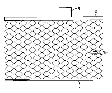
Known prior art grid designs, such as shown in Figs.
1-3, include a top frame member 2 and a bottom frame member
3 joined by a plurality of metal wires 4 forming a pattern
interposed between the frame members 2, 3. A lug 5 formed
as an integral part of the top frame member 2 is
interconnected with adjacent grids in a battery.
Known grid patterns include a diamond pattern,
characterized by wires defining diamond shaped grid cells,
such as shown in Figs. 1 and 2, a rectangular pattern,
characterized by rectangular grid cells, a radial pattern
characterized by wires extending radially from a common
point, such as shown in Fig. 3, and other grid patterns,
such as disclosed in U.S. Patent No. 5,582,936. These
CA 02371416 2001-11-15
WO 00/72393 PCT/US00/12569
- 2 -
particular patterns have certain advantages and
disadvantages which are discussed in further detail below.
Battery grids are commonly manufactured by processes,
such as casting, expanded metal forming, and stamping.
Cast battery grids are manufactured by pouring molten lead
into a mold, allowing the lead to cool, and then separating
the grid from the mold. The casting process is capable of
producing a variety of efficient grid designs, which are
limited only by the ability of mold makers to make the
mold.
The casting process is, however, an expensive process
which discourages its use. The process requires the use of
a mold coating to facilitate separation of the grid from
the mold, and for an increased throughput, a plurality of
expensive molds are required. Furthermore, even with
multiple molds, the casting process is still a batch
process which tends to have a lower productivity (i.e.,
produces less product over a given time period) than a grid
manufacturing process which is "continuous," such as
expanded metal forming.
Grids formed from expanded metal are less expensive
than molded grids because of the higher productivity of the
expanded metal forming process over the casting process.
In the expanded metal process, battery grids are formed by
expanding metal through a process in which a strip of cast
or wrought lead material is pierced and then pulled or
expanded. In a conventional expanded metal grid, the grid
mass is substantially evenly distributed across the grid,
and the grid is limited in wire pattern, wire shape, and
lead distribution.
CA 02371416 2001-11-15
WO 00/72393 PCT/US00/12569
- 3 -
Two particularly common expanded metal forming
processes, rotary expansion and reciprocated expansion,
have been developed. In the rotary expansion process, a
lead strip is cut with a rotary cutter, the wires are
extruded above and below the plane of the strip and then
expanded in the horizontal directions to form a diamond
grid pattern interposed between top and bottom frame
members. In the reciprocated expansion process, wires
defining a diamond grid pattern are cut and expanded in a
direction perpendicular to a surface of the strip. After
expansion, the strip is rotated 90°, and the grid is
coined. The size of the diamond and the wire width are
variables in either process.
The wire angle and wire size of an expanded metal grid
pattern are limited to ensure proper expansion without
breaking the wires. The wire angle, as shown in Fig. 1, is
the angle A of the grid wires with respect to the top or
bottom frame member 2, 3, and is typically less than 40° in
an expanded metal grid. This wire angle limitation creates
a zigzag path for current to flow through the grid. The
zig-zag pattern increases the grid resistance because the
current does not flow directly to the collecting lug, such
as in a radial grid formed by casting.
The wire size limitation also limits the taper rate to
15% or less for the rotary process, and 60% or less for the
reciprocated process. The taper rate, best illustrated in
Fig. 3, is the rate at which a wire width can be changed
along its length. For example, with a 15% taper rate, the
maximum wire width near the current collecting lug is 15%
wider at the grid top than that at the grid bottom.
CA 02371416 2001-11-15
WO 00/72393 PCT/US00/12569
- 4 -
More lead mass in the lug area would enhance the
current carrying capability of the grid and reduce the grid
resistance because the current generated in a plate flows
toward the lug. These features are difficult to achieve
using the expansion process. Thus, the conductivity of
expanded metal grids tend to be lower than a similar size
cast grid.
Furthermore, there is no side frame in an expanded
metal grid to restrict growth of the wires. Thus, the
service life of an expanded metal grid is considerably
shorter than the cast equivalent due to the upward growth
of a positive expanded grid in a battery resulting in
either shorting with an adjacent negative strap or loss of
positive active materials.
BRIEF SUMMARY OF THE INVENTION
The present invention provides a battery grid,
suitable for use in a lead-acid battery, with a grid upper
portion having a grid wires defining a first grid pattern,
and a grid lower portion electrically connected to the grid
upper portion. The grid lower portion has grid wires which
define a second grid pattern. The first grid pattern is
different from said second grid pattern to improve the
conductivity of the grid.
In another aspect of the present invention, a battery
grid includes a top frame member. Non-expanded metal wires
extending from the top frame member are electrically
connected to expanded metal wires to form a multi pattern
grid.
CA 02371416 2001-11-15
WO 00/72393 PCT/iJS00/12569
- 5 -
The general objective of the present invention is to
provide a battery grid with improved conductivity. This
objective is accomplished by providing a grid having more
than one grid pattern.
Another objective of the present invention is to
provide a battery grid which can be produced using a high
productivity process. This objective is accomplished by
providing a method of making a battery grid which includes
a metal expanding process.
Yet another objective of the present invention is to
extend the service life of the grid. This objective is
accomplished by incorporating a second grid pattern with an
enlarged top frame portion and/or side frames, the service
life of the grid can be extended because of reduced growth
grid.
These and still other objects and advantages of the
present invention will be apparent from the description
which follows. In the detailed description below,
preferred embodiments of the invention will be described in
reference to the accompanying drawings. These embodiments
do not represent the full scope of the invention. Rather
the invention may be employed in other embodiments.
Reference should therefore be made to the claims herein for
interpreting the breadth of the invention.
BRIEF DESCRIPTION OF THE DRAWINGS
Fig. 1, is a schematic of a prior art battery grid
having a diamond pattern;
Fig. 2 is a schematic of another prior art battery
grid having a diamond pattern;
CA 02371416 2001-11-15
WO 00/72393 PCT/US00/12569
- 6 -
Fig. 3 is a schematic of a prior art battery grid
having a radial pattern;
Fig. 4 is a schematic of a battery grid incorporating
the present invention with an upper portion having a
rectilinear grid pattern;
Fig. 5 is a schematic of a battery grid incorporating
the present invention with an upper portion having a radial
grid pattern;
Fig. 6 is a schematic of another battery grid
incorporating the present invention with an upper portion
having a radial grid pattern; and
Fig. 7 is a schematic of a battery grid incorporating
the present invention with a rectilinear grid pattern
joined to an upper portion of a battery grid having a
diamond grid pattern.
DETAILED DESCRIPTION OF THE PREFERRED EMBODIMENTS
The present invention provides an improved expanded
metal lead-acid battery grid. As shown in Fig. 4, a lead-
acid battery grid 10 has a top frame member 12 and an
opposing bottom frame member 14. A lower portion 16 of the
grid 10 includes a plurality of expanded metal wires 24
defining a diamond grid pattern, and extend from the bottom
frame member 14 toward the top frame member 12. The
expanded metal wires 24 are joined to an upper portion 18
of the grid 10 which include a plurality of wires 26
defining a rectilinear grid pattern extending from the top
frame member 12 toward the bottom frame member 14. The
wires 24, 26 are electrically connected to allow electrical
current to flow therebetween.
CA 02371416 2001-11-15
WO 00/72393 PCT/US00/12569
A current collection lug 28 is formed as an integral
part of the top frame member 12, and, preferably, includes
an enlarged conductive section, such as described in U.S.
Patent No. 5,582,936, which is fully incorporated herein by
reference. Preferably, the mass of the wires 26 in the
upper portion of the grid is greater than the mass of the
expanded metal grid wires 24 to improve grid conductivity.
Fig. 5 and 6, disclose additional, more preferred,
embodiments of the present invention, and have like
c~-nbonents referenced with the same reference.numbers and
differentiated with a ""' or "' "' .
Desirable grid patterns provide a grid 10 with a low
grid resistivity, which translates into a high efficiency,
and a low grid weight. Resistivity of Grid, RG, and grid
efficiency can be calculated by methods known in the art,
such as by modeling a grid as a network of resistors. The
grid efficiency is defined to be the geometric area of the
grid divided by RG and grid weight. RG is defined to be the
overall resistance times the geometric area of the grid.
The grid weight is calculated by multiplying grid density
with the total volume of the wire members.
In one well known model for determining RG, each wire
is assumed to act as a resistor, and its resistance is
determined by the conductivity of the grid material, length
and the average cross-section of the wire. The potential
and current distributions in a grid can be determined by
application of Kirchhoff's first law to each grid node,
namely, that the algebraic sum of all currents flowing into
the node, i.e., the junction of wire members, must be zero.
Assuming homogeneous distribution of current, the total
CA 02371416 2001-11-15
WO 00/72393 PCT/US00/12569
_ g _
current flow through a grid under a given voltage drop is
calculated and the overall grid resistance is defined by
Ohm's law. Details of this modeling technique are
described in the literature (W. Tiedemann, J. Newman and F.
DeSua in Power Sources 6, D.H. Collins Ed., Academic, New
York, 1976).
Using the modeling technique described above,
resistivity and efficiency of several grid designs
including a cast grid with a radial wire pattern,
conventional expanded metal grids, and grids incorporating
the present invention were calculated. The grids are
described, and the calculated results are compared in
Example I below. The grid parameters and calculated
results are also tabulated in Table I.
Examgle I
All the grids in this example are 4.00" tall and 5.69"
wide. Grid 1, schematically shown in Fig. 1, is
conventional 0.035" thick rotary 22-row expanded metal
grid, 4.00" tall and 5.69" wide, and a diamond size of
0.542" long and 0.34" wide with 0.035" wide wires. Grid 2,
schematically shown in Fig. 2, is an expanded metal grid
like Grid 1 but with a smaller diamond. Grid 3,
schematically shown in Fig. 4, incorporates the present
invention, with a stamped rectilinear wire pattern (wire
spacing = 0.542")in a grid upper portion and an
expanded metal diamond pattern with 12 rows at a grid lower
,6
portion x6'''. Grid 4, schematically shown in Fig. 5, is
similar to Grid 3, but has 12 expanded diamond rows at the
lower portion 16'and a radial pattern in the grid upper
CA 02371416 2001-11-15
WO 00/72393 PCT/US00/12569
_ g _
portion 18'. The maximum radial wire width in this grid is
0.120". Grid 5, is the same as Grid 4 except the maximum
radial wire width being 0.150" which allows a higher taper
rate (0.011" per row vs 0.009" in Grid 4). Grid 6,
schematically shown in Fig. 6, is the same as Grid 5
except that there are only 8 expanded diamond rows at the
lower portion 16" . The cast grid, schematically shown on
Fig. 3, is a cast grid having a radial pattern with the
parameters disclosed in Table I.
The data in Table I clearly suggests that the cast
grid with a radial wire pattern has the best grid
conductivity and efficiency. The grid efficiency of the
expanded metal grids is only 50o to 600 of the cast grid.
As shown in Table I, the conductivity and efficiency of an
expanded metal grid will be higher if the diamond size is
smaller (Grid 2 vs Grid 1). Replacing the diamond pattern
with a rectilinear pattern in the upper portion of the
grid, the resistivity is lowered and the efficiency
increases (Grid 3 vs Grid 1). The radial wire pattern in
the upper portion of the grid is better than the
rectilinear pattern (Grid 4 vs Grid 3). Wider radial wires
near the lug improves grid conductivity and efficiency
(Grid 5 vs Grid 4). Bigger radial-wire portion on the top
(Grid 6 vs Grid 5) improves grid conductivity and
efficiency.
Comparing Grid 6 and the cast grid, even though Grid 6
is 6.7 g heavier, the efficiency of Grid 6 is 83% of the
cast grid, an increase of 60% over the conventional
expanded metal grid. The difference in grid resistivity is
less than 4o which translates into a difference in cold
CA 02371416 2001-11-15
WO 00/72393 PCT/US00/12569
- 10 -
crank voltage of about 16 mV per battery under a typical
cold crank current density. This difference is within the
variation among batteries and is negligible. A slightly
heavier grid and a little difference in cold crank voltage
are a small price to pay comparing to cost savings because
the grids including a diamond pattern can be formed using a
"continuous" process which can be produced significantly
faster than the cast grids.
Table I. Grid Resistivity and Efficiency of,Conventional
Designs and the Invention
Grid Cast Grid 1 Grid 2 Grid 3 Grid 4 Grid 5 Grid 6
Frame Thickness0.043"0.035" 0.035" 0.035" 0.035" 0.035" 0.035"
Wire Thickness0.032"0.035" 0.035" 0.035" 0.035" 0.035" 0.035"
Wire Pattern RadialDiamond DiamondRect/DiaRad/DiaRad/Dia Rad/Dia
Diamond LengthN/A 0.542" 0.466" 0.542" 0.542" 0.542" 0.542"
Diamond WidthN/A 0.340" 0.340" 0.340" 0.340" 0.340" 0.340"
Top Frame 0.250"0.200" 0.188" 0.200" 0.200" 0.200" 0.200"
Width
# of Exp. 0 22 22 12 12 12 8
Rows
Vertical Wire
Spacing:
Maximum 0.458"0.542" 0.466" 0.542" 0.542" 0.542" 0.542"
Minimum 0.287"0.542" 0.466" 0.542" 0.287" 0.287" 0.287"
Max. Wire 0.170"0.041" 0.051" 0.120" 0.120" 0.150" 0.150"
Width
Wire Taper/row0.010"0.00 D.00 0.008" 0.009" 0.011" 0.011"
Grid Weight/(g)41.86 40.58 47.48 45.42 46.78 46.98 48.56
Grid RG/ (C~.:cm'~0.348 0.697 0.497 0.432 0.401 0.390 0.360
Efficiency(S/g)10.1265.218 6.256 7.520 7.873 8.061 8.441
One method of forming a grid incorporating the present
invention includes the steps of expanding outer portions of
CA 02371416 2001-11-15
WO 00/72393 PCT/iJS00/12569
- 11 -
a wide strip to form the lower portion of a grid; stamping
an inner unexpanded portion of the strip with a radial wire
pattern and the lug to form the upper part of the grid.
In Example II described below, a grid incorporating
the present invention is compared to prior art grids. The
experimental results comparing the efficiencies of prior
art grids to a grid incorporating the present invention are
disclosed in Table II below.
Example II
Conventional rotary expanded grids, 4.00" tall and
5.69" wide, of various thickness and a diamond size of
0.542" long and 0.34" wide with 0.035" wide wires were
measured for overall resistance by passing a current
through the lugs of two grids placed in parallel in a
sulfuric acid electrolyte and measure the voltage drop from
lug to the bottom frame on the far side. The grid weight
and RG of these expanded metal grids and a cast grid
equivalent are listed as the control group in Table II.
A grid 30 incorporating the present invention,
schematically shown in Fig. 7, is formed by overlaying and
then spot welding a lead strip 32 of 0.008" thickness onto
a 0.030" thick expanded metal grid 34. The lead strip has
a 2" wide pre-stamped rectilinear pattern with 0.2" frames
31 and rails 33 0.5" apart. Upon joining the lead strip 32
to the expanded metal grid 34, the grid 30 has a .038"
thick upper portion 36, and .030" thick lower portion 38.
The grid weight and RG of this grid are listed in Table II
under "Test."
CA 02371416 2001-11-15
WO 00/72393 PCT/I1S00/12569
- 12 -
One can see from Table II that the conventional
expanded metal grid is inferior to the cast grid equivalent
in grid conductivity and efficiency. For example, the
difference in RG of the 0.037" strip and the cast grid
would be responsible for 0.27 V difference in cold crank
voltage under a typical cold crank current density. The
test grid is 5 g lighter, the resistance is 200 lower, and
efficiency is 40% higher than that of the 0.037" thick
grid. With the test grid, the cold crank voltage is only
0.16 V lower and yet the grid is 8 g lighter than the cast
equivalent. One can match the grid weight of the cast grid
by attaching a second strip with a more efficient pattern,
such as a radial wire pattern, and with more lead to
further reduce the difference in grid resistivity and thus
the cold crank voltage.
Table II. Features of Grids
Grid Wt. la) Grid RG(Wcm2) Effi ciency(S/a)
Control Group (Expanded Mold Cast):
Metal and
Book
0.030" Strip 33.52 0.820 4.829
0.033" Strip 33.94 0.821 4.767
0.035" Strip 39.53 0.706 4.756
0.037" Strip 40.16 0.691 4.777
Book 43.10 0.329 9.398
Mold
Cast
Test .008" Strip):
(0.030"
Strip
+ 0
0.038" Total 35.07 0.561 6.732
CA 02371416 2001-11-15
WO 00/72393 PCT/US00/12569
- 13 -
The grid 10, shown in Fig 5, may be produced by
forming a lead strip into a radial wire pattern having a
lug 28, by methods known in the art, such as stamping,
cutting, and the like, forming a grid upper frame member 12
and grid upper portion 18. The radial wire pattern strip
is joined to a grid lower portion 16 formed from an
expanded metal strip using methods known in the art, such
as lamination, spot-welding, or the like. The joined
strips provide a battery grid 10 having different upper and
lower grid patterns to provide improved conductivity.
While there has been shown and described what are at
present considered the preferred embodiment of the
invention, it will be obvious to those skilled in the art
that various changes and modifications can be made therein
without departing from the scope of the invention defined
by the appended claims. For example, more than two grid
patterns may be joined to improve the conductivity of a
battery grid over prior art grids.