Note: Descriptions are shown in the official language in which they were submitted.
CA 02371525 2001-10-24
WO 00/65939 PCT/GB00/01637
APPARATUS FOR MAHING RESEALABLE POUCHES
The present invention relates to apparatus for making resealable
pouches, such as those used for storing tobacco, which pouches comprise
a pocket having a resealable fastener.
According to a first aspect of the present invention there is
provided a guide plate for use in apparatus for producing a resealable
pouch for tobacco, the guide plate having a lengthwise extending edge
over which a thermoplastic film is folded and a lengthwise extending slot
parallel to said edge for receiving a resealable fastener in a closed
condition between the film on both sides of the guide plate, the slot being
closed at its downstream end so as to open the resealable fastener.
Preferably, downstream of the closed end of the slot is a groove on
each side of the plate for receiving respective parts of the resealable
fastener. With one preferred construction there is provided a recess
downstream of the oppositely disposed grooves, which recess enables the
fastener to be closed at predetermined locations along its length. In a
2 0 preferred arrangement the upstream ends of the groove taper to a point
coinciding with the downstream end of the slot.
According to a second aspect of the present invention there is
provided apparatus for producing a resealable pouch for tobacco
2 5 comprising feed means for a thermoplastic film, feed means for a two-part
resealable fastener, a film guide for folding the thermoplastic film over a
guide plate and inside lateral guide walls, said guide plate having a
lengthwise extending edge over which the film is folded and a lengthwise
extending slot parallel to said edge for receiving the resealable fastener in
0
a closed condition, the slot being closed at its downstream end so as to
open the fastener, and welding heater means upstream of the end of the
slot for securing the two parts of the resealable fastener to the film on
respective sides of the guide plate.
35 In one arrangement downstream of the closed end of the slot is a
lengthwise extending groove on each side of the plate for receiving
CA 02371525 2001-10-24
WO 00/65939 PCT/GB00/01637
2
respective parts of the resealable fastener. Conveniently the upstream
ends of the groove taper to a point coinciding with the downstream end of
the slot.
Preferably, downstream of the closed end of the slot are fastener
crushers which compress and weld the ends of the fastener at
predetermined intervals according to the desired length of pouch. Ideally
the fastener crushers act on the fastener by virtue of a recess in the guide
plate, which recess is downstream of the grooves.
In preferred arrangements downstream of the fastener crushers are
side heaters for welding the sides of the pouch from the fold to the
fastener and also downstream of the side heaters is a cutter for cutting
along each side weld, perpendicular to the fold, to produce individual
pouches.
Ideally cooling means are provided directly after the welding
heater means for the fastener. Conveniently said cooling means comprise
liquid cooled blocks.
A preferred feature is that there is provided transfer means for
2 0 transferring the pouches to a tobacco filling head and also closing means
for closing the fastener of each pouch after filling.
According to a third aspect of the present invention the closing
means comprises a pivotted roller bar having an elongate operative
2 5 surface adapted to progressively engage the fastener along its length and
urge it closed against a portion of the transfer means. Preferably said
operative surface is arcuate and the roller bar is spring biased into an
initial end position and the roller bar is movable against the spring by
pneumatic means.
An embodiment of the present invention will now be described in
more detail. The description makes reference to the accompanying
drawings in which
Figure 1 is a section through a tobacco pouch having a resealable
3 5 fastener,
CA 02371525 2001-10-24
WO 00/65939 PCT/GB00/01637
3
Figure 2 shows a general plan view of a pouch manufacturing
machine,
Figure 3 is a simplified plan view of part of the figure 2 machine,
Figure 4 is a side view of a guide plate portion of the machine
shown in figure 3,
Figure 5 is a side view of the guide plate,
Figures 6 and 7 are exaggerated cross-sections on lines VI-VI and
VII-VII of figure 5 in use,
Figure 8 is a front view of one type of welding anvil used in the
machine,
Figure 9 is a side view of a closing head, and
Figure 10 is a plan view of a fastener closer used in the closing
head.
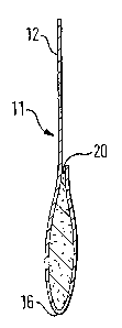
In the figures there is shown a machine 10 for producing
resealable pouches 11, filling the pouches 11 with a product such as
tobacco and closing the pouches 11. The pouches 11 are formed from a
thermoplastic material the form of a film 12 which is capable of being
welded to itself using heat, pressure or a combination of both. Some as
aspects of the machine 10 are known from machines for making and
filling conventional tobacco pouches.
The film 12 is delivered from a reel 13 via a series of rollers 14 to
2 5 ~ A-frame 15 which narrows in a downstream direction to initiate a
lengthwise fold 16 in the continuous film 12. Downstream of the A-frame
15 the fold 16 is supported by a lengthwise extending top edge 17 of a
substantially vertical guide plate 18. The film 12 on each side of the
guide plate 18 passes between a pair of vertical guide rollers 19 and is
restrained by outer guide panels disposed on either side of the guide plate
18.
A continuous resealable fastener 20 is delivered at the same speed
as the film 12 from another reel 21 and fed into a lengthwise extending
slot 22 formed in the guide plate 18. The main part of the slot 22 is
substantially parallel to the top edge 17 of the guide plate 18 so that the
CA 02371525 2001-10-24
WO 00/65939 PCT/GB00/01637
4
fastener 20 is positioned between the film 12 on each side of the guide
plate, generally parallel to the fold 16 in the film 12 although there is in
this embodiment an optional, slightly arcuate lead-in to the slot 22. The
fastener 20 comprises two parts 23, 24 each having an attachment surface
25 facing respective parts of the film 12 on either side of the guide plate
18. The openable/closable interconnection feature of the fastener 20 is
not shown in detail.
Once the fastener 20 is in position, welding heaters 26, disposed
on both sides of the guide plate 18, weld the film 12 on both sides of the
guide plate to the respective attachment surfaces 25 of the fastener 20.
Immediately following the welding of the fastener 20 in position the film
12/fastener 20 assembly passes through a cooling section which may
comprise fluid cooled blocks 27 adjacent the laterally outermost surfaces
of the film 12. In the embodiment illustrated the welding heaters and
cooling blocks 26, 27 are contained in a single unit.
Downstream of the cooling blocks 27, the slot 22 is closed by way
of an outwardly tapering abutment 28 which causes the two parts 23, 24
2 0 of the fastener 20 to separate, thus opening the fastener. The two parts
23,
24 of the fastener 20 are now received in respective lengthwise extending
grooves 29, 30 which have cross-sections designed to receive the
interlocking features of the parts 23, 24 of the fastener 20. This ensures
2 5 that the film 12 remains close to the guide 18 and the two parts 23, 24 of
the fastener remain in general alignment.
After separation of the two parts of the fastener 20, the
film/fastener combination passes a pair of oppositely disposed zip
crushing and welding stations 31 which are aligned with a recess 32 in the
guide plate. Each zip crushing station 31 is pneumatically movable
towards and away from the guide plate 18 and the other zip crushing
station 31. The zip crushing stations 31 are adapted to heat the
fastener/film ultrasonically and on one side have a pair of anvils 33 for
cooperation with anvils 34 on the opposite zip crushing station. The
opposed pairs of anvils 33,34 act through the recess 32 to close the
CA 02371525 2001-10-24
WO 00/65939 PCT/GB00/01637
fastener 20 at predetermined locations and weld the fastener 20 shut at
these locations.
In practise, the operation of the machine will be timed such that
the fastener 20 is welded closed at equal spaces along its length, the
lengthwise distance between welds defining the mouths of the pockets of
the eventual pouches. Also the welds extend a short distance below the
attachment surfaces 25 of the fastener 20 for reasons which will become
apparent.
The anvils 33 present to the anvils 34 a knurled surface but the
anvils 34 have a generally smooth surface 35 with a horizontally
extending concave groove 36 to accommodate the fastener 20. This
combination of anvils 33, 34 produces a smoother finish on the front of
the pack by virtue of the anvils 34.
The film/fastener combination then passes a pair of side welding
stations 37 which form vertical side welds extending from the fold 16 in
the film to the crush welds of the fastener 20. The extension of the crush
weld a short distance below the fastener 20 ensures that the side weld is
2 0 e~y to form with no interference with the fastener such that the pouch is
substantially air-tight.
The combination then moves to a cutter 38 which cuts down the
centre of the side welds and the remainder film 12 aligned therewith to
2 5 form individual pouches 11 each with a resealable fastener 20 across its
open mouth.
The open pouches are then inverted and pass individually towards
a filling turret 39 after an optional blast of compressed air into the
pouches to eliminate any partial closing of the fastener 20 which may
have occurred.
After filling, the pouches 11 are placed individually into
successive grippers 40 of a fastener closing head 41 which rotates at a
speed linked to the speed of the remainder of the machine. Mechanical
linkages 42 cause the grippers 40 to grip the pouches 11 below the
fastener 20 whilst the conventional flap 43 of the pouch folds over the rest
of the pouch 11 due to its entrainment inside the guide surface 44.
CA 02371525 2001-10-24
WO 00/65939 PCT/GB00/01637
6
A rolling fastener closer 45 acts through a gap in the guide surface
44 and closes the fastener 20 whilst the closing head 41 is momentarily
stationery. The closer 45 has a pivoted roller bar 46 which engages the
pouch 11 adjacent the fastener 20 and presses the fastener closed along its
length against a gripper member 47 of the gripper 40.
The roller bar 46 rotates about pivot 48 and is loaded by way of a
spring 49 into one of its extreme positions as shown in figure 10. The
roller bar 46 is pneumatically rotated about the pivot 48 against the spring
49 in order for it to perform its fastener closing action, as shown in broken
lines in figure 10.
After closure of the fastener 20 the pouch 11 is deposited on to a
conveyor 50 to take it to a final wrapping station (not shown).
During the formation of the pouch 11 the film 12 is actually pulled
through the guide plate area by means of vertical drive rollers 51 and a
tensioning unit 52.
25
35