Language selection

Search

Patent 2371856 Summary

Third-party information liability

Some of the information on this Web page has been provided by external sources. The Government of Canada is not responsible for the accuracy, reliability or currency of the information supplied by external sources. Users wishing to rely upon this information should consult directly with the source of the information. Content provided by external sources is not subject to official languages, privacy and accessibility requirements.

Claims and Abstract availability

Any discrepancies in the text and image of the Claims and Abstract are due to differing posting times. Text of the Claims and Abstract are posted:

  • At the time the application is open to public inspection;
  • At the time of issue of the patent (grant).
(12) Patent Application: (11) CA 2371856
(54) English Title: METHOD OF INTERCONNECTING TWO ELEMENTS
(54) French Title: PROCEDE PERMETTANT D'INTERCONNECTER DEUX ELEMENTS
Status: Deemed Abandoned and Beyond the Period of Reinstatement - Pending Response to Notice of Disregarded Communication
Bibliographic Data
(51) International Patent Classification (IPC):
  • H05K 5/00 (2006.01)
  • B29C 65/00 (2006.01)
  • B29C 65/02 (2006.01)
  • B29C 65/48 (2006.01)
  • B29C 65/54 (2006.01)
  • H04M 1/02 (2006.01)
(72) Inventors :
  • HOLMBERG, PER (Sweden)
(73) Owners :
  • TELEFONAKTIEBOLAGET LM ERICSSON
(71) Applicants :
  • TELEFONAKTIEBOLAGET LM ERICSSON (Sweden)
(74) Agent: MARKS & CLERK
(74) Associate agent:
(45) Issued:
(86) PCT Filing Date: 2000-02-16
(87) Open to Public Inspection: 2000-08-24
Availability of licence: N/A
Dedicated to the Public: N/A
(25) Language of filing: English

Patent Cooperation Treaty (PCT): Yes
(86) PCT Filing Number: PCT/SE2000/000298
(87) International Publication Number: WO 2000049843
(85) National Entry: 2001-08-17

(30) Application Priority Data:
Application No. Country/Territory Date
9900575-3 (Sweden) 1999-02-18

Abstracts

English Abstract


In a method of interconnecting two elements (10, 11) of plastic material by
welding or gluing together surfaces of the elements a channel (12) is formed
in one of said elements, which is divided by partitions (16) into individual
spaces distributed longitudinally of the channel. The partitions and the side
walls (14, 15) of the channel along the edge surfaces (17, 18, 19, 20) thereof
are connected with the other element (11) by welding or gluing together said
edge surfaces.


French Abstract

La présente invention concerne un procédé permettant d'interconnecter deux éléments (10, 11) en matière plastique par soudage ou collage des surfaces de ces éléments. L'un de ces éléments est formé d'un canal (12), qui est divisé par des séparations (16) en espaces individuels répartis longitudinalement sur le canal. Les séparations et les parois latérales (14, 15) du canal au niveau de leurs bords de surface (17, 18, 19, 20) sont connectés à l'autre élément (11) par soudage ou collage.

Claims

Note: Claims are shown in the official language in which they were submitted.

5
CLAIMS
1. A method of interconnecting two elements (10, 11)
of plastic material by welding or gluing together surfaces
of the elements, characterized in that a channel (12) is
formed in one (10) of said elements, said channel being
divided by partitions (16, 25) into individual spaces
distributed longitudinally of the channel, and that said
partitions and the side walls (14, 15) of the channel along
the edge surfaces (17, 18, 19, 20, 23, 26) thereof are
connected with the other element (11) by welding or gluing
together said edge surfaces.
2. A method according to claim 1 characterized in
that the channel (12) is formed in an edge portion of said
one element (10).
3. A method according to claim 1 or 2 characterized
in that the partitions are formed as individual transverse
walls (16) in the channel (12).
4. A method according to claim 3 characterized in
that said other element (11) forms a ridge (21) fitting
into a recess formed by the edge surface (17, 18) of each
individual transverse wall (16).
5. A method according to any of claims 1 to 4
characterized in that the channel (12) is formed with
rectangular cross sectional shape.
6. A method according to any of claims 1 to 4
characterized in that the channel forms a transversely
curved bottom wall merging into the side walls of the
channel
7. A method according to claim 1 or 2 characterized
in that the channel (12) has rectangular cross sectional
shape and that the partitions are formed by a waved wall
(25) extending longitudinally of the channel (12) and being
connected to the bottom and side walls (13, 14, 15)
thereof.

6
8. An element (10) of plastic material to be
connected to a cover (11) of plastic material by welding or
gluing characterized by a channel (12) formed in said
element, which is divided by partitions (16, 25) into
individual spaces distributed longitudinally of the
channel, said partitions and the side walls of the channel
being arranged for contact with the cover along the edge
surfaces thereof.

Description

Note: Descriptions are shown in the official language in which they were submitted.


CA 02371856 2001-08-17
WO 00/49843 PCT/SE00/00298
Ti tle of the Invention
Method of interconnecting two elements
Background of the invention
Field of the invention
The invention relates to a method of interconnecting
l0 two elements of plastic material by welding or gluing
together surfaces of the elements. The elements to be
interconnected can comprise parts of a housing for an
electronic unit, particularly a mobile phone, or a housing
for one or more batteries to be used in such units.
Description of the Prior Art
When elements forming a housing of the kind referred
to above are interconnected by welding or gluing such
interconnection is effected at edge surfaces of the
elements. If the joint between the elements is damaged e.g.
by shock against the housing such as when it is dropped to
the floor this will result in a connection being opened
between the interior of the housing and the surroundings so
that foreign matter such as liquids, dust, gases and dirt
can penetrate into the interior of the housing, which may
be detrimental to the components received therein or to the
function thereof.
Brief Summary of the Invention
The purpose of the invention is to overcome this
drawback which is achieved by the method of the kind
referred above having obtained the characterizing features
of claim 1. If the housing formed by the two elements
interconnected by the method of the invention is exposed to
chock it can be expected that the connection between the
two elements is broken only at one side wall of the channel

CA 02371856 2001-08-17
WO 00/49843 PCT/SE00/00298
2
and possibly also at one or two partitions therein and that
the connection of the elements otherwise is intact. This
means that foreign matter can penetrate into a few
compartments and will be trapped therein, no direct
connection between the surroundings and the interior of the
housing being opened up by the shock. By the invention
there is thus produced a tight housing effectively
protecting the components received by the housing also
under sever conditions, said housing thus being well suited
l0 for heavy duty use.
Brief Description of the Drawings
Illustrative embodiments of the invention will be
described with reference to the accompanying drawings in
which
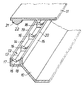
FIG 1 is a fragmentary cross sectional view of two
elements to be interconnected by the method of the
invention in one embodiment thereof,
FIG 2 is a fragmentary perspective view of the
elements in FIG 1,
FIG 3 is a perspective view similar to FIG 2 of a
second embodiment of the invention, and
FIG 4 is a perspective view similar to FIG 2 of a
third embodiment of the invention.
Detailed Description of the Invention
In the illustrative embodiment disclosed in FIGS 1
and 2 one element 10 of plastic material forms a trough,
and another element 11 also of plastic material is to be
connected with the element 10 as a cover to form together
with element 10 a watertight housing which shall enclose an
electronic unit, a battery or another delicate equipment
that has to be protected against foreign matter such as
liquids, dust, gases, and dirt, and which is suitable for
use under severe conditions. When the method of the

CA 02371856 2001-08-17
WO 00/49843 PCT/SE00/00298
3
invention is applied for interconnecting the two elements a
channel 12 is formed at the edge of element 10 said channel
having a bottom wall 13 and two side walls, an outer side
wall 14 and an inner side wall 15. In the channel there are
formed a number of partitions 16 extending transversely of
the channel and joining integrally the bottom and side
walls thereof. The upper edge of each partition forms two
edge surfaces 17 and 18 enclosing an obtuse angle and
located slightly below the edge surfaces 19 and 20 of the
l0 side walls 14 and 15, respectively.
The other element 11 on the lower side thereof is
formed with a rib 21 at the edge of the element. The rib is
continuous and has the same extension as the channel 12.
The rib has such width that it fits into the channel
between the side walls 14 and 15 thereof, and the end
surface 22 of the rib forms the same angle as the edge
surfaces of the partitions 16. When the two elements 10 and
11 are brought together the rib 21 contacts at the end
surface 22 thereof the edge surfaces of the partitions 16
and the lower side of the element 11 is brought into
contact with the edge surfaces 19 and 20 of the side walls
14 and 15. Before this is done one of the mutually
contacting surfaces is coated with a glue or a solvent for
the plastic material of which the elements 10 and 11 are
made, in order to sealingly attach the contacting surfaces
with each other, or the mutually contacting surfaces after
having been brought into contact with each other are
interconnected by ultra-sound or friction welding. If
welding is applied a positive tolerance can be provided
between the rib and the channel surplus material being
melted away during welding.
The rib 21 can extend intermittently along the
channel rib portions being provided only at the sites
opposite to the partitions.

CA 02371856 2001-08-17
WO 00/49843 PCT/SE00/00298
4
In the embodiment of FIG 3 the partitions 16 have
their edge surfaces 23 flush with the edge surfaces 19 and
20 of the side walls 14 and 15. The element 11 has a plane
lower surface 24 which is brought into contact with and
welded or glued to the edge surfaces 19, 20 and 23.
FIG 4 discloses a further embodiment wherein the
partitions are replaced by a waved wall 25 extending along
the channel and having the upper edge surface 26 flush with
the edge surfaces 19 and 20 of the side walls 14 and 15,
the waved wall being integral with the bottom wall 13 and
also with the side walls 14 and 15 at the wave peaks of the
waved wall.
Any other configuration can be adhered to in order to
provide individual closed cells along the joint between the
two elements. The bottom wall can be curved transversely
and merge into the side walls of the channel as an
alternative to the rectangular cross sectional shape in the
embodiment of FIGS. 1 to 3.

Representative Drawing
A single figure which represents the drawing illustrating the invention.
Administrative Status

2024-08-01:As part of the Next Generation Patents (NGP) transition, the Canadian Patents Database (CPD) now contains a more detailed Event History, which replicates the Event Log of our new back-office solution.

Please note that "Inactive:" events refers to events no longer in use in our new back-office solution.

For a clearer understanding of the status of the application/patent presented on this page, the site Disclaimer , as well as the definitions for Patent , Event History , Maintenance Fee  and Payment History  should be consulted.

Event History

Description Date
Inactive: IPC from MCD 2006-03-12
Application Not Reinstated by Deadline 2004-02-16
Time Limit for Reversal Expired 2004-02-16
Deemed Abandoned - Failure to Respond to Maintenance Fee Notice 2003-02-17
Letter Sent 2002-07-25
Inactive: Single transfer 2002-05-17
Inactive: Cover page published 2002-03-19
Inactive: Courtesy letter - Evidence 2002-03-19
Inactive: Notice - National entry - No RFE 2002-03-15
Application Received - PCT 2002-03-13
Application Published (Open to Public Inspection) 2000-08-24

Abandonment History

Abandonment Date Reason Reinstatement Date
2003-02-17

Maintenance Fee

The last payment was received on 2001-08-17

Note : If the full payment has not been received on or before the date indicated, a further fee may be required which may be one of the following

  • the reinstatement fee;
  • the late payment fee; or
  • additional fee to reverse deemed expiry.

Please refer to the CIPO Patent Fees web page to see all current fee amounts.

Fee History

Fee Type Anniversary Year Due Date Paid Date
Basic national fee - standard 2001-08-17
MF (application, 2nd anniv.) - standard 02 2002-02-18 2001-08-17
Registration of a document 2002-05-17
Owners on Record

Note: Records showing the ownership history in alphabetical order.

Current Owners on Record
TELEFONAKTIEBOLAGET LM ERICSSON
Past Owners on Record
PER HOLMBERG
Past Owners that do not appear in the "Owners on Record" listing will appear in other documentation within the application.
Documents

To view selected files, please enter reCAPTCHA code :


To view images, click a link in the Document Description column. To download the documents, select one or more checkboxes in the first column and then click the "Download Selected in PDF format (Zip Archive)" or the "Download Selected as Single PDF" button.

List of published and non-published patent-specific documents on the CPD .

If you have any difficulty accessing content, you can call the Client Service Centre at 1-866-997-1936 or send them an e-mail at CIPO Client Service Centre.


Document
Description 
Date
(yyyy-mm-dd) 
Number of pages   Size of Image (KB) 
Representative drawing 2002-03-18 1 9
Drawings 2001-08-17 2 35
Claims 2001-08-17 2 52
Description 2001-08-17 4 152
Abstract 2001-08-17 1 49
Cover Page 2002-03-19 1 37
Notice of National Entry 2002-03-15 1 195
Courtesy - Certificate of registration (related document(s)) 2002-07-25 1 134
Courtesy - Abandonment Letter (Maintenance Fee) 2003-03-17 1 178
PCT 2001-08-17 7 285
Correspondence 2002-03-15 1 31